Note: Descriptions are shown in the official language in which they were submitted.
1
A medical system, a device for collecting chordae and/or leaflets and a method
therefor.
BACKGROUND OF THE INVENTION
Field of the Invention
This invention pertains in general to the field of medical devices for
improvement of
heart valves, such as mitral, aortic or tricuspid valves, as well as tools and
methods therefore.
More particularly the invention relates to a medical system for short time
replacement, support
and/or repair of a native valve, a device for collecting and arranging chordae
and/or leaflets to
hold and/or stabilize an artificial valve in a desired position and a method
of delivering an artificial
valve for short time replacement of a native valve in a heart.
Description of the Prior Art
During heart surgery, a premium is placed on reducing the amount of time used
to
replace and repair valves as the heart is frequently arrested and without
perfusion.
Thus, it would be advantageous to have an artificial valve temporarily
replacing a native
valve to be repaired or replaced during the repair or replacement.
Furthermore, since a premium is placed on reducing the amount of time used to
replace
and/or repair valves, there is not a lot of time for making decisions,
preparing and/or performing
surgery/medical intervention. Thus, it would also be advantageous to have more
time to make
decisions, for preparations and/or for performing surgery or medical
intervention. This may be
important, especially since it will lead to an improved quality of the
replacement or repair.
The use of an artificial valve has been disclosed in US20070219630 Al.
However, as
can be seen from e.g. fig. 5 and [0129] in this document, the temporary valve
is placed away from
the mitral valve. Furthermore, as can be seen in [0075] of this document, a
mitral valve
separation unit is needed for proper function. Moreover, the flow is in the
embodiments described
in this document directed through conduits (refer to e.g. conduits 130, 140,
330, 340, 430, 440)
and thus not through the native valve.
The construction of the temporary valve function as a whole is thus rather
complicated.
Furthermore, since the artificial valve is placed away from the native valve,
it cannot utilize parts
of the native valve for e.g. positioning and securing of the artificial valve.
In W02012/095159 A2 a ring-shaped prosthetic valve is disclosed for
permanently
replacing an atrioventricular heart valve that comprises an annular body on
which valvular cusps
are fastened for insertion into a valve annulus of the heart.
CAN_DMS: \132976470\1
Date Recue/Date Received 2020-04-16
2
In US2007/255396 Al a girdle is disclosed for surrounding the chordae tendinae
of a
heart valve.
In US2007/038293 Al a device and methods for endoscopic annuloplasty are
disclosed. Opposed valve leaflets may be temporarily grasped and held into
position prior to
permanent attachment. No replacement valve is disclosed in US2007/038293 Al.
It may thus be advantageous to have a temporary valve which is of a simple and
cost-
effective construction. It may further be advantageous to have means for fast
and easy fixation
and stabilization of an artificial valve for temporary use. Furthermore, it
may be advantageous to
have means for fast and/or easy temporary replacement of a native valve.
Moreover, it may be
advantageous to have means for fast and easy positioning of a temporary
artificial valve. In
addition, it may be advantageous to have means for collecting and arranging
chordae to hold
and/or stabilize the artificial valve in a desired position.
Hence, an improved system or device would be advantageous and in particular a
system or device for repair and/or replacement of a native valve allowing for
increased flexibility
and cost-effectiveness.
SUMMARY OF THE INVENTION
Accordingly, examples of the present invention preferably seek to mitigate,
alleviate or
eliminate one or more deficiencies, disadvantages or issues in the art, such
as the above-
identified, singly or in any combination by providing a medical system, a
device for collecting
chordae and method therefor.
According to aspects of the disclosure, a medical system and a device for
collecting
chordae and/or leaflets as well as a method of delivery therefor are
disclosed, whereby fast and
easy replacement of a native valve, fast and easy positioning of a temporary
artificial valve, and
improved quality of repair and/or replacement of a native valve may be
achieved.
According to one aspect of the disclosure, a medical system for short time
replacement
and repair of a native valve is provided. The system comprises an artificial
valve and a device for
collecting and arranging chordae and/or leaflets to hold and/or stabilize the
artificial valve in a
desired position. The device comprises a unit for grasping a plurality of
chordae and/or leaflets.
According to another aspect of the disclosure, a device for collecting and
arranging
chordae and/or leaflets to hold and/or stabilize an artificial valve in a
desired position is provided.
The device comprises a unit for grasping a plurality of chordae and/or
leaflets.
According to yet another aspect of the disclosure, a method of delivering an
artificial
valve for short time replacement of a native valve, such as a mitral valve or
an aortic valve, in a
heart is provided. The method comprises positioning the artificial valve
inside the native valve.
The method further comprises pulling a plurality of chordae and/or leaflets
together and towards
CAN_DMS: \132976470\1
Date Recue/Date Received 2020-04-16
3
the artificial valve for fixation of the artificial valve. The method also
comprises deploying a clip to
surround the artificial valve and/or to keep the chordae and/or leaflets in
position towards the
artificial valve. The method may also comprise gaining trans-apical access to
the heart.
Furthermore, the method may comprise forwarding a catheter, via a trans-apical
route, into the
left ventricle of the heart. Alternatively, the method may comprise forwarding
a catheter, via an
aortic route into the ascending aorta of said heart (12). Moreover, the method
may comprise
passing the catheter at least partly through the native valve. In addition,
the method may
comprise removing the catheter.
Some examples of the disclosure provide for more time for making decisions
about how
to perform surgery.
Some examples of the disclosure provide for more time for preparing surgery.
Some examples of the disclosure provide for more time for performing surgery
or
medical intervention.
Some examples of the disclosure provide for an improved quality of repair or
replacement of a native valve.
Some examples of the disclosure provide for a simple and/or a reliable
temporary valve
function.
Some examples of the disclosure provide for that the tube does not interfere
with
annuloplasty.
Some examples of the disclosure provide for reliable securing of the temporary
valve.
Some examples of the disclosure provide for fast and/or easy replacement of a
native
valve.
Some examples of the disclosure provide for fast and/or easy positioning of a
temporary valve.
Some examples of the disclosure provide for that simple and/or fast deployment
of a
clip is enabled.
Some examples of the disclosure provide for a fast and easy collection of
chordae.
Some examples of the disclosure provide for fast and easy securing of the
temporary
valve.
Some examples of the disclosure provide for fast and easy tightening to
minimize
paravalvular leakage.
Some examples of the disclosure provide for a procedure that is less prone to
errors,
and thus a faster and easier securing of the valve.
Some examples of the disclosure provide for reliable securing of valve and
chordae.
CAN_DMS: \132976470\1
Date Recue/Date Received 2020-04-16
4
Some examples of the disclosure enable precise positioning of an implant or a
valve in
the anatomically correct position.
Some examples of the disclosure provide for that the procedure or surgery can
be
performed with high accuracy.
Some examples of the disclosure provide for an easier and/or less invasive
delivery
method.
Some examples of the disclosure provide for fast and easy collection of
chordae.
Some examples of the disclosure provide for a fast and easy way of delivering,
positioning and/or securing a temporary valve from outside the body of a
patient.
Some examples of the disclosure provide for a reliable securing of a temporary
valve
and chordae.
Some examples of the disclosure enable beating heart surgery.
Some examples of the disclosure provide for a reduced leakage.
Some examples of the disclosure provide for a minimized regurgitation during
e.g.
beating heart surgery.
It should be emphasized that the term "comprises/comprising" when used in this
specification is taken to specify the presence of stated features, integers,
steps or components
but does not preclude the presence or addition of one or more other features,
integers, steps,
components or groups thereof.
BRIEF DESCRIPTION OF THE DRAWINGS
These and other aspects, features and advantages of which examples of the
invention
are capable of will be apparent and elucidated from the following description
of examples of the
present invention, reference being made to the accompanying drawings, in which
Fig. 1A is a schematic cross-sectional view of a patient with a heart;
Fig. 1B is a schematic perspective view of a mitral valve and an aortic valve;
Fig. 2 is a schematic cross-sectional view of a mitral valve;
Fig. 3A is a schematic cross-sectional view of a mitral valve with a catheter
inserted into
the left ventricle;
Fig. 3B is a schematic cross-sectional view of an aortic valve with a catheter
inserted
into the aortic arc and partly into the ascending aorta;
Fig. 4A is a schematic cross-sectional view of a mitral valve with a catheter
partly in the
left atrium;
Fig. 4B is a schematic cross-sectional view of an aortic valve with a catheter
partly in
the ascending aorta;
CAN_DMS: \132976470\1
Date Recue/Date Received 2020-04-16
5
Fig. 5A is a schematic cross-sectional view of a mitral valve with a valve
being
delivered;
Fig. 5B is a schematic cross-sectional view of an aortic valve with a valve
being
delivered;
Fig. 6A is a schematic cross-sectional view of a mitral valve with a valve for
short time
replacement of the mitral valve;
Fig. 6B is a schematic cross-sectional view of an aortic valve with a valve
for short time
replacement of the aortic valve;
Fig. 7A-C are schematic illustrations of a principle of a valve for short time
replacement
of a native valve;
Figs. 8A-B are schematic perspective views of a collecting unit for collecting
and
arranging chordae towards a valve;
Fig. 9 is a schematic view of a clip used to secure a valve;
Fig. 10 and 11 are perspective views of various collecting units for
collecting and
arranging chordae towards a valve;
Figs. 12A-B are schematic perspective views of a collecting unit for
collecting and
arranging chordae towards a valve, which unit comprises two hooks, arms or
balloons; and
Figs. 13A and 13B are schematic perspective views in partial cross-section
which
illustrate retracting of chordae.
DESCRIPTION OF THE PREFERRED EXAMPLES
Specific examples of the invention will now be described with reference to the
accompanying drawings. This invention may, however, be embodied in many
different forms and
should not be construed as limited to the examples set forth herein. Rather,
these examples are
provided so that this disclosure will be thorough and complete, and will fully
convey the scope of
the invention to those skilled in the art. The terminology used in the
detailed description of the
examples illustrated in the accompanying drawings is not intended to be
limiting of the invention.
In the drawings, like numbers refer to like elements.
The following description focuses on an example of the present disclosure
applicable to
a native valve of the heart and in particular to a mitral and an aortic valve.
However, it will be
appreciated that the disclosure is not limited to this application but may be
applied to many other
native valves including for example a tricuspid valve or a pulmonary valve.
Fig. 1A illustrates a patient 10 having a heart 12 shown in cross-section
including a left
ventricle 14 and a right ventricle 16. The concepts of the present disclosure
are suitable to be
applied, for example, to a mitral valve 18, which supplies blood into the left
ventricle 14 or to an
CAN_DMS: \132976470\1
Date Recue/Date Received 2020-04-16
6
aortic valve 34. The tricuspid valve (15) and the pulmonary valve (17) are
also shown in Fig. 1A.
Native mitral valve 18, also shown in Fig. 1B, includes an annulus 20 and a
pair of leaflets 22, 24
which selectively allow and prevent blood flow into the left ventricle 14.
Leaflets 22, 24 are
supported for coaptation by chordae tendinae, chordae or chords 26, 28
extending upwardly from
respective papillary muscles 30, 32. Blood enters the left ventricle 14
through the mitral valve 18
and is expelled during subsequent contraction of heart 12 through aortic valve
34. The aortic
valve 34 controls blood flow to the aorta and organs connected to the aorta.
It will be appreciated
that the present disclosure may also be applicable to a tricuspid heart valve
(15).
Fig. 2 is a cross-sectional view of a mitral valve 18 and surroundings. The
left atrium 44,
the left ventricle 14, the chordae 26, 28 and the mitral valve 18 can be seen
in this figure.
Fig. 3A illustrates a catheter 310, which is being utilized for delivering a
valve for short
time replacement of a native valve, such as the mitral valve 18. The catheter
310 may be inserted
into the left ventricle 14 of the heart in any known way. The catheter 310 is
in some examples
inserted via a transapical route. In these examples trans-apical access to the
heart is gained and
the catheter 310 will be forwarded, via the trans-apical route, into the left
ventricle 14 of the heart.
Once the catheter has entered the left ventricle 14, the catheter is forwarded
so that it is
at least partly put through the mitral valve 18 and partly into the left
atrium 44 as illustrated in Fig.
4A. The catheter 310 may be the delivery system for all implements used in the
procedure. Thus,
the catheter 310 may be utilized also for delivery of chordae collection
devices, commissure
locating tools and/or annuloplasty devices for long-term use. Thereafter, the
valve for short-time
replacement 502, which may be an artificial valve, is positioned inside the
native mitral valve 18.
This is illustrated in Fig. 5A. In order to facilitate the delivery of the
valve 502 and to enable the
positioning of the valve 502, the valve 502 may be collapsible for delivery
and/or expandable
upon delivery. This may be achieved by the use of an at least partly flexible
valve. As an
example, a flange of the valve 502 may be flexible during delivery. Once the
valve 502 has been
positioned inside the native valve, a plurality of chordae may be pulled
together and towards the
valve 502 for fixation of the valve 502.
Pulling of a plurality of chordae together is in some examples performed for
creation of
a temporary space between at least one chorda and a ventricular wall of the
heart. Within this
temporary space, an annuloplasty device may pass for delivery. Thus, an
additional space may
be created between e.g. at least two chordae and a ventricular wall of the
heart by pulling a
plurality of chordae together. Through the additional space an annuloplasty
device may be
advanced into position. The insertion of an annuloplasty device is preferably
performed after the
valve 502 has been positioned.
CAN_DMS: \132976470\1
Date Recue/Date Received 2020-04-16
7
The plurality of chordae may in some examples be pulled together by rotation
or
twisting of the valve 502. The rotation of the valve 502 for pulling the
chordae together is
preferably specified to one direction, such as anticlockwise rotation. The
rotation of the valve 502
may be actuated by rotating a catheter. As an example, a two-axis steerable
catheter may be
used for actuating the rotation of the valve 502.
A clip may thereafter be deployed to surround the valve 502 and/or to keep the
chordae
in position towards the valve 502. In some examples, the clip is deployed by
pushing it out of the
catheter 310 and into position with a pusher or a pushing catheter.
Alternatively or in addition, the
clip may be delivered with a special clip guide tube. The catheter 310 may
thereafter be removed
or utilized for inserting further implants or devices, such as an annuloplasty
device. The valve 502
may remain inside the native valve during positioning of an annuloplasty
device. Once an
annuloplasty device has been inserted for permanent implantationõ positioned
and secured, the
temporary, short-term, valve 502 is removed.
Fig. 3B illustrates a catheter 310, which is being utilized for delivering a
valve for short
time replacement of a native valve, such as the aortic valve 34. The catheter
310 may be inserted
via the aortic arc at least partly into the ascending aorta 52. In these
examples, the catheter
enters for instance trans-femorally from the groin and goes via aorta at least
partly into the
ascending aorta 52 for delivery of the valve at the aortic valve 34.
Once the catheter has entered the ascending aorta 52, the catheter is
forwarded so that
it is at least partly put through the aortic valve 34 and partly into the left
ventricle 14 as illustrated
in Fig. 4B. The catheter 310 may be the delivery system for all implements
used in the procedure.
Thus, the catheter 310 may in addition be utilized also for delivery of
chordae collection devices,
commissure locating tools and/or annuloplasty devices for long-term use.
Thereafter, the valve for
short-time replacement 502, which may be an artificial valve, is positioned
inside the native aortic
valve 34. This is illustrated in Fig. 5B. In order to facilitate the delivery
of the valve 502 and to
enable the positioning of the valve 502, the valve 502 may be collapsible for
delivery and/or
expandable upon delivery. This may be achieved by the use of an at least
partly flexible valve. As
an example, a flange of the valve 502 may be flexible during delivery. Once
the valve 502 has
been positioned inside the native valve, a plurality of chordae may be pulled
together and towards
the valve 502 for fixation of the valve 502.
Pulling of a plurality of chordae together is in some examples performed for
creation of
a temporary space between at least one chorda and a ventricular wall of the
heart. Within this
temporary space, an annuloplasty device may pass for delivery. Thus, an
additional space may
be created between e.g. at least two chordae and a ventricular wall of the
heart 12 by pulling a
plurality of chordae together. Through the additional space an annuloplasty
device may be
CAN_DMS: \132976470\1
Date Recue/Date Received 2020-04-16
8
advanced into position. The insertion of an annuloplasty device is preferably
performed after the
valve 502 has been positioned.
The plurality of chordae may in some examples be pulled together by rotation
or
twisting of the valve 502. The rotation of the valve 502 for pulling the
chordae together is
preferably specified to one direction, such as anticlockwise rotation. The
rotation of the valve 502
may be actuated by rotating a catheter. As an example, a two-axis steerable
catheter may be
used for actuating the rotation of the valve 502.
A clip may thereafter be deployed to surround the valve 502 and/or to keep the
chordae
in position towards the valve 502. In some examples, the clip is deployed by
pushing it out of the
catheter 310 and into position with a pusher or a pushing catheter.
Alternatively or in addition, the
clip may be delivered with a special clip guide tube. The catheter 310 may
thereafter be removed
or is alternatively utilized for inserting further implants or devices, such
as an annuloplasty device.
The valve 502 may remain inside the native valve during positioning of an
annuloplasty device.
Once an annuloplasty device has been inserted, positioned and secured, the
valve 502 is
removed.
The valve 502, shown in Figs. 6A and 6B, is for short time replacement of a
native valve
in a heart and the valve 502 may be positioned through the native valve upon
implantation. The
valve 502 comprises an at least partially collapsible and/or at least
partially expandable tube 602.
Furthermore, the valve 502 comprises a flange 604. The flange 604 may be
flexible during
delivery, and is preferably somewhat rigid once the valve 502 has been
implanted. The flange
604 prevents the valve 502 from moving out of position from e.g. the left
atrium 44 towards the
left ventricle 14 if the valve is for the mitral valve 18 and from moving out
of position from e.g. the
ascending aorta towards the aortic arc if the valve is for the aortic valve
34.
In some examples, the valve 502 is a one-way valve comprising a tube 602
having an
inlet side 704 and an outlet side 706. This is depicted in Fig. 7A-C. The tube
602 may be flexible.
This may be advantageous, since the use of a flexible tube prevents
interference between the
tube 602 and annuloplasty devices. Alternatively, the tube 602 may be rigid or
at least somewhat
rigid. The valve 502 may further comprise a flexible inner sleeve 702 attached
to an inlet side 704
of the tube 602 and positioned inside the tube 602. This is depicted in fig.
7A. The flexible inner
sleeve 702 may be made of a flexible material such as rubber. In fig. 7A, the
pressure inside the
tube 602 is similar to the pressure at the inlet side 704 of the tube 602.
Therefore, the flexible
inner sleeve 702 has more or less a same pressure on an inside of the sleeve
702 which is in
contact with the inlet side 704, as on an outside of the flexible inner sleeve
702 which is in contact
with the outlet side 705, thus making the valve partly open. In Fig. 7b the
pressure inside the tube
602 has increased so that the pressure inside the tube 602, outside of the
flexible inner sleeve
CAN_DMS: \132976470\1
Date Recue/Date Received 2020-04-16
9
702 and in the left ventricle 14 is larger than the pressure at the inlet of
the tube 602, inside of the
flexible inner sleeve 702 and the left atrium 44. When the pressure inside the
tube 602 becomes
higher than the pressure at and/or outside the inlet of the tube, the valve
502 closes by the
flexible inner sleeve 702 contracting together. In Fig. 70 the pressure inside
the tube 602 and
outside of the flexible inner sleeve 702 is lower than the pressure at or
outside the inlet of the
tube 704 and inside of the flexible inner sleeve 702. When the pressure inside
the tube 602
becomes lower than the pressure at or outside the inlet of the tube, the valve
502 and flexible
inner sleeve 702 opens. Thus, a simple, yet reliable replacement valve is
obtained by the
construction of a valve 502 as illustrated in Figs. 7A-7C. The flange 708 can
also be seen in Fig.
7A. The flange 708 may be expandable. In one example, the flange 708 is an
expandable
balloon.
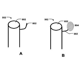
Fig. 8A illustrates an example, wherein a collecting unit 802 is utilized for
collecting and
arranging chordae towards the valve 502. The collecting unit 802 may together
with the tube 602
form one integral part. Alternatively, the collecting unit 802 may be
attachable or attached to the
tube 602. In some examples, the collecting unit 802 comprises a single arm or
a single hook.
Alternatively or in addition, the collecting unit 802 comprises a ring and/or
a fluid-filled balloon. A
collection unit 802 comprising a fluid-fillable or fluid-filled balloon 804 is
depicted in Fig. 8B. The
collection unit 802 may in addition to the fluid-fillable or fluid-filled
balloon 804 comprise a single
arm.
In some examples the valve 502 comprises the collecting unit 802 for
collecting and
arranging chordae towards the valve 502. The valve may be secured, held and/or
stabilized in a
desired position by the collecting and arranging of chordae towards the valve
502. Thus, a
reliable securing of the valve 502 may be achieved.
By the use of a collecting unit 802, fast and easy replacement of a native
valve may be
achieved. Furthermore, fast and easy positioning of a temporary valve may be
obtained.
Therefore, the use of a collecting unit may contribute to give more time to
make decisions related
to surgery, more time to prepare for surgery and/or more time to perform
surgery or medical
intervention. Thus, overall quality of valve replacement or repair may be
improved. The securing
of the valve with chordae together with the shape of the valve 502 and a
correct dimensioning of
the valve 502 may be advantageous, since a valve with proper dimensions
secured by the
chordae does not press against any ventricular wall. Thus, there will be no
damage to the
ventricular walls. Although, there may be a small leakage outside the valve
502, this may be
acceptable for a short period of time, such as minutes, hours or a few days.
The valve may thus in certain examples include a collecting unit for
collecting and
arranging chordae towards the valve. The valve is thus secured, held and/or
stabilized in a
CAN_DMS: \132976470\1
Date Recue/Date Received 2020-04-16
10
desired position by the collecting unit and arranging of chordae towards said
valve. In an example
the collecting unit includes a clip, wherein the chordae and/or leaflets are
kept in position towards
the valve with said clip. The clip may form a helix. The clip, in particular
when in form of a helix,
may be integral with or connected to the collecting unit and not a separate
piece. Hence, in some
examples, the collecting unit 802 may comprise a clip. Fig. 9 illustrates such
a clip 902. The
chordae are kept in position towards the valve 502 with the clip 902. The clip
902 may be formed
as a ring or ring-like structure. Alternatively, the clip 902 may be formed or
shaped as a helix.
Thereby, the clip 902 can easily be rotated into position. Rotation is
preferably made together
with the valve when the collecting unit, such as a clip, in particular when in
form of a helix, is
integral with the collecting unit. The chordae and/or leaflets are the kept in
position towards the
valve with said collecting unit and secured with said clip. This may be
advantageous, since a
simple and/or fast deployment of the clip 902 is enabled thereby. Furthermore,
reliable securing,
simple and/or fast deployment of a clip is enabled. Alternatively, when the
clip, in particular when
in form of a helix, is a separate piece and not integral with or unconnected
with the valve, the
collecting unit may be rotated separately into position. The clip may then be
applied to the
collecting unit for securing the latter in position at the chordae and/or
leaflets.
Fig. 10 illustrates a valve 502 having a collecting unit for collecting and
arranging
chordae towards the valve 502 according to some examples. In these examples
the collecting
unit is shaped as a ring or ring-like structure. The ring-shaped unit 1002 may
be extended to a
rod-like structure for delivery and changeable into a ring-like structure upon
delivery or
implantation. Thus, it may be advantageous to have a collecting unit shaped as
a ring, since it
may facilitate delivery.
Fig. 11 illustrates a valve 502 having a collecting unit for collecting and
arranging
chordae towards the valve 502 according to some examples. In these examples
the collecting
unit is a fluid-filled balloon 1102. The fluid-filled balloon 1102 may be ring-
like The use of a fluid-
filled balloon 1102 as a collecting unit may be advantageous, since the use of
a balloon facilitates
delivery and since fluid may be used to stabilize the balloon and/or give some
rigidity to the
balloon. In one example, the balloon is filled with fluid upon or after
delivery at the native valve.
Fig. 12A illustrates a collecting unit for collecting and arranging chordae
towards the
valve 502 according to some examples. In these examples the collecting unit
comprises two
hooks 802, 1202 or arms. Alternatively, the collecting unit comprises a
plurality, such as four, of
hooks or arms. The hooks or arms are preferably positioned equidistantly
around the valve 502,
i.e. the hooks or arms are preferably equidistantly distributed exteriorly
along the valve 502. A
collection unit comprising two fluid-fillable or fluid-filled balloons 804,
1206 is depicted in Fig. 12B.
The collection unit may in addition to the fluid-fillable or fluid-filled
balloons 804, 1206 comprise
CAN_DMS: \132976470\1
Date Recue/Date Received 2020-04-16
11
two arms. Alternatively, the collecting unit comprises a plurality, such as
four, of fluid-fillable or
fluid-filled balloons. The fluid-fillable or fluid-filled balloons are
preferably positioned equidistantly
around the valve 502, i.e. the fluid-fillable or fluid-filled balloons are
preferably equidistantly
distributed exteriorly along the valve 502.
In some examples, the collecting unit collects and arranges the chordae
towards the
valve 502 during rotation of the valve 502. The rotation is preferably
anticlockwise rotation. The
rotation of the valve 502 may be actuated by rotating a catheter, such as a
two-axis steerable
catheter. Thus, fast and easy collection of chordae may be achieved.
Furthermore, fast and easy
securing of the valve may be achieved. In addition, with a steerable catheter,
fast and easy
collection of chordae from outside the body of a patient may be achieved.
Moreover, by
specifying a direction of rotation, such as clockwise or anticlockwise, a
procedure that is less
prone to errors, and thus a faster and easier securing of the valve, may be
obtained. In addition,
reliable securing of the valve 502 and the chordae may be achieved.
In some examples, the valve 502 comprises a collecting unit for collecting and
arranging leaflets towards the valve 502. In these examples, the valve 502 is
secured, held
and/or stabilized in a desired position by the collecting and arranging of
leaflets towards the valve
502. In one example, the valve 502 is secured, held and/or stabilized in a
desired position by the
collecting and arranging of leaflets towards the valve 502 and by the
collecting and arranging of
chordae towards the valve 502. In some examples, the valve comprises a
collecting unit for
collecting and arranging chordae and leaflets towards the valve 502.
Figs. 13A and 13B illustrate retracting of chordae. Fig. 13A illustrates
retracting of
chordae with a collection unit comprising a hook, an arm or a wire. A first
end of a steerable
catheter or wire 1310 exits a side lumen 1302 of the delivery catheter 310.
The steerable catheter
1310 is then moved and manipulated by a user so as to surround the chordae
1340, without
touching any ventricular wall 1320. The end of the catheter 1310 moves in a
radial direction away
from the delivery catheter 310 towards the ventricular wall 1320 as it is
advanced and/or rotated.
Once the catheter 1310 has encircled all the chordae 1340 and 360 degree
coverage of the
space is achieved, an end unit of the steering catheter or wire 1310 is
activated to pull the
chordae 1340 together. Activation may include rotation of the catheter or
valve 502 whereupon
the curvature of the end of the catheter having grasped the chordae pulls them
together towards
the valve. The delivery catheter 310 is held stationary during the whole
deployment of the
steerable catheter or wire 1310.
Fig. 13B illustrates retracting of chordae 1340 with a collection unit
comprising two fluid-
fillable or fluid-filled balloons. The delivery catheter 310 has two side
lumens, which are
equidistantly distributed around the delivery catheter 310, i.e. 180 degrees
apart. The two balloon
CAN_DMS: \132976470\1
Date Recue/Date Received 2020-04-16
12
catheters 1330, 1332 exits the side lumens of the delivery catheter 310. The
balloon catheters
1330, 1332 are then manipulated and moved towards a ventricular wall 1320 past
the chordae
1340. Once the two balloon catheters are in position between the ventricular
wall 1320 and the
chordae 1340, the balloons may be inflated or filled with a fluid. When the
balloons have been
inflated or filled with a fluid, the balloons will fill the space between the
ventricular wall 1320 and
the chordae 1340 and press the chordae 1340 away from the ventricular wall and
towards the
centre and towards each other, i.e. the balloons will encapsulate the chordae
1340 and tighten
the native valve and bring the chordae 1340 towards the delivery catheter 310.
The surfaces of
the balloons may be provided with grooves, which form hollow channels when the
balloons are
fully inflated or fluid-filled. These channels may then guide a ring or a
replacement valve during
deployment.Below, a medical system for short time replacement and repair of a
native valve is
described. The medical system comprises a valve 502. The valve 502 is in these
examples an
artificial valve. Furthermore, the medical system comprises a device for
collecting and arranging
chordae to hold and/or stabilize the artificial valve in a desired position.
The device comprises a
unit for grasping a plurality of chordae. With the medical system a fast and
easy replacement of a
native valve may be achieved. Furthermore, fast and easy positioning of a
temporary artificial
valve may be achieved. Moreover, use of the medical system may contribute to
give more time to
make decisions related to surgery, more time to prepare for surgery and/or
more time to perform
surgery/medical intervention. Thus, overall quality of e.g. valve replacement
may be improved.
In some examples, the medical system comprises a steerable catheter for
delivering the
artificial valve; an annuloplasty device, which may be used to perform
annuloplasty, i.e. to
reshape the valve annulus, in order to improve the function of the valve; a
location valve
expander and/or a clip for locking the chordae in positions towards the
artificial valve. This may
enable fast and easy replacement of a native valve. Furthermore, it may enable
fast and easy
positioning of a temporary artificial valve.
Below, a device for collecting and arranging chordae to hold and/or stabilize
an artificial
valve in a desired position is described. The device may be a medical device,
and comprises a
unit for grasping a plurality of chordae. With the device, a fast and easy
replacement of a native
valve may be achieved. Furthermore, fast and easy positioning of a temporary
artificial valve may
be achieved. Moreover, use of the medical system may contribute to give more
time to make
decisions related to surgery, more time to prepare for surgery and/or more
time to perform
surgery/medical intervention. Thus, overall quality of e.g. valve replacement
may be improved.
In some examples, the unit for grasping a plurality of chordae comprises an
arm, a
hook, a ring and/or a fluid-filled balloon. These examples provide for an easy
way of grasping
and/or collecting the chordae.
CAN_DMS: \132976470\1
Date Recue/Date Received 2020-04-16
13
In some examples, the artificial valve is collapsible for delivery.
Alternatively or in
addition, the artificial valve may be expandable upon delivery. Furthermore,
the device may be
attachable to or integrable with the artificial valve. Thus, the device may be
attached to or
integrated with the artificial valve. These examples provide for an easier and
less invasive
delivery.
In some examples, the unit for grasping a plurality of chordae comprises a
plurality of
hooks. The number of hooks may be three, four or any other suitable number.
Preferably, the
hooks are positioned on opposite sides of the artificial valve. The hooks may
also be equidistantly
or symmetrically distributed exteriorly along the artificial valve.
In some examples, the catheter 310 enters from the groin and goes via a venous
route
transseptally to the right atrium 44 for delivery of the valve 502.
The medical system described herein may be utilized for short-term replacement
of a
native valve and/or for temporary use during beating heart surgery. The device
described herein
may be utilized for short-term replacement of a native valve and/or for
temporary use during
beating heart surgery. The valve 502 may be utilized during beating heart
surgery. Thus, the
system, the device and/or the valve 502 may enable beating heart surgery.
Furthermore, the
valve 502 may be utilized during life saving intervention, intervention in
acute leaflet and/or
chordate rupture.
The system, the device and or the valve 502 may provide for a reduced leakage
and/or
a minimized regurgitation during e.g. beating heart surgery. Furthermore, the
system, the device
and or the valve 502 may enable precise positioning of an implant or valve 502
in the
anatomically correct position. Moreover, the procedure used for delivering a
valve 502 described
herein enables high accuracy of delivery, positioning and securing of a
temporary valve 502.
Within this disclosure the term short-time or short-time replacement has been
used.
Short-term replacement and/or repair of native valves is considered to be a
temporary
replacement. Such a temporary replacement may be a replacement that last for
minutes, hours or
possibly up to a few days. Short-term replacement includes non-indwelling,
i.e. non-permanently
implanted, devices and methods described herein. Short-term replacement
devices are intended
to be removed from the body after use. With a long-time replacement is herein
meant a
replacement, which last for several days, weeks, months or longer. Such a long-
time replacement
may be made with devices intended to be permanently implanted and not removed
from the
body, such as indwelling annuloplasty devices. Structural requirements for
such devices are thus
different for short-term use and long-term use. As used herein, the singular
forms "a", "an" and
"the" are intended to include the plural forms as well, unless expressly
stated otherwise. It will be
further understood that the terms "includes," "comprises," "including" and/or
"comprising," when
CAN_DMS: \132976470\1
Date Recue/Date Received 2020-04-16
14
used in this specification, specify the presence of stated features, integers,
steps, operations,
elements, and/or components, but do not preclude the presence or addition of
one or more other
features, integers, steps, operations, elements, components, and/or groups
thereof. It will be
understood that when an element is referred to as being "connected" or
"coupled" to another
element, it can be directly connected or coupled to the other element or
intervening elements may
be present. Furthermore, "connected" or "coupled" as used herein may include
wirelessly
connected or coupled. As used herein, the term "and/or" includes any and all
combinations of one
or more of the associated listed items.
Unless otherwise defined, all terms (including technical and scientific terms)
used
herein have the same meaning as commonly understood by one of ordinary skill
in the art to
which this disclosure belongs. It will be further understood that terms, such
as those defined in
commonly used dictionaries, should be interpreted as having a meaning that is
consistent with
their meaning in the context of the relevant art and will not be interpreted
in an idealized or overly
formal sense unless expressly so defined herein.
The present disclosure has been described above with reference to specific
examples.
However, other examples than the above described are equally possible within
the scope of the
disclosure. Different method steps or a different order thereof than those
described above may be
provided within the scope of the disclosure. The different features and steps
of the disclosure
may be combined in other combinations than those described. The scope of the
disclosure is only
limited by the appended patent claims.
CAN_DMS: \132976470\1
Date Recue/Date Received 2020-04-16