Note: Descriptions are shown in the official language in which they were submitted.
Attorney Ref.: 1147P065CA01
SHEET CONSTRUCTION AND
METHODS OF MAKING AND USING THE SAME
TECHNICAL FIELD
[0001] The present invention relates generally to sheet constructions that
are configured
to be fed through a printer and more particularly to a sheet construction and
methods of making
and using the same.
BACKGROUND
[0002] Certain print-receptive media of the type used to create small-size
printed
products, such as, but not limited to, business cards, ROLODEX-type cards,
greeting cards, place
cards, invitations, identification badges, and address labels, because of
their small sizes, cannot
be fed individually into and easily printed onto using conventional ink jet
printers, laser printers,
photocopiers, and other ordinary printing and typing devices. Therefore, one
known method of
producing such printed products has been to print desired indicia on different
portions of a
standard-sized sheet of print-receptive material, such as a letter-size sheet
(i.e., 8.5 inches x 11
inches), a legal-size sheet (i.e., 8.5 inches x 14 inches), or an A4- size
sheet (i.e., 8.27 inches x
11.69 inches), and then to cut the sheet with a suitable cutting device into
individual small-size
printed media. However, this method is disadvantageous because the user must
have access to
such a cutting device, and the separate cutting step is cost and time
inefficient.
[0003] In order to avoid the above-described cutting step, another
known product has the
perimeters of the media (e.g., the business cards) formed using a grid of
horizontal and vertical
microperforation lines extending the full length and width of the sheet.
Although these
microperforations are typically small and close together, with typically more
than fifty
microperforations per inch, when the cards are separated from one another by
tearing along the
microperforation lines, perfectly clean edges for the media typically do not
result. Instead, the
edges for the media are usually slightly fuzzy, giving the media a less
professional appearance
than media produced by cutting with a cutting device.
-1-
CA 2899379 2019-11-15
Attorney Ref.: 1147P065CA01
[0004] Accordingly, a first alternate approach to the above-described
use of
inicroperforations is disclosed in U.S. Patent No. 5,993,928, inventor Popat.
which issued
November 30, 1999. According to this first alternate approach. there is
provided a card stock
sheet having two parallel pairs of substantial-cut lines extending the length
of the sheet and
engaging the sheet at both ends
-1a-
CA 2899379 2019-11-15
Attorney Ref.: 1147P065CA01
thereof. The substantial-cut lines extend about 90% through the thickness of
the sheet from the
front towards the back surface. The sheet is then die cut with short (through-
cut) lines extending
widthwise between the lines of each pair, or vice versa. The substantial-cut
and through-cut lines
form on the sheet two columns of business card blanks, with paper waste strips
at the side (and
end) margins and between the columns. After being passed through a printing
device, the printed
cards are separated from one another by tearing or pulling along the
substantial-cut lines. No
further separation is required along the through-cut lines.
[00051 A second alternate approach is disclosed in U.S. Patent
Application Publication
No. US 2001/0007703 Al, inventors Weirather et al., which was published July
12, 2001.
According to this second alternate approach, there is provided a dry laminated
business card
sheet construction. The construction includes a low density polyethylene film
layer extrusion
coated on a densified bleached kraft paper liner to form a film-coated liner
sheet. A facestock
sheet is adhered with a layer of hot melt adhesive to the film layer to form a
laminate sheet web,
which is rolled on a roll. The facestock sheet, the film layer and the
adhesive layer together
define a laminate feedstock. The roll is transported to and loaded on a press
with the liner side
up. One or both edges of the web are crushed with a calendaring die to form
thin lead-in edge(s).
The web is die cut on the bottom face, up through the laminate facestock, but
not through the
paper liner, to form the perimeters of a grid of blank business cards or other
printable media.
with a waste paper frame of the laminate encircling the grid. The web is then
die cut from the top
through the paper liner and to, but not through, the laminate facestock, to
form liner strips
covering the back face of the laminate facestock. According to one embodiment,
alternate ones
of the strips are then pulled off of the laminate facestock web. A final
production step is to sheet
the web to form the desired sheet width (or length) of the laminated sheet
construction. The
individual laminated business card sheets can be stacked into the infeed tray
of an ink jet printer.
for example, and the sheets individually and automatically fed, lead-in edge
first, into the printer
and a printing operation performed on each of the printable media, to form a
sheet of printed
media. The remaining strips on the back of the laminate facestock cover the
lateral cut lines in
the laminate facestock and, thereby, holds the facestock together as it is fed
into and passed
through the printer. The user then individually peels the printed media off of
the strips and out
-2-
CA 2899379 2019-11-15
Attorney Ref.: 1147P065CA01
from the waste paper frame. Thereby, printed business cards (or other printed
media), each with
its entire perimeter defined by clean die cuts, are formed.
[0006] A third alternate approach is disclosed in U.S. Patent
Application Publication
No. US 2003/0148056 Al, inventors Utz et al., which was published on August 7,
2003.
According to this third alternate
-2a-
CA 2899379 2019-11-15
Attorney Ref.: 1147P065CAO
approach, there is provided a card sheet including a top material having
punched lines, the front
side of the top material being printable. A carrier material of at least one
polymer layer is directly
applied, as by extruding, to the back side of the top material. The polymer
has a stress-at-break in
the range of 10 to 30 MPa and an elongation at break in the range of 10 to
120%. From the card
sheet, individual cards can be broken out to form high quality calling
(business) cards,
photograph cards, postcards or the like.
100071 A fourth alternate approach is disclosed in U.S. Patent No.
7,625.619, inventors
Hodson et al., which issued on December 1, 2009. According to this fourth
alternate approach,
there is provided a label sheet construction including a liner sheet and a
facestock sheet
releasably adhered to the liner sheet. A plurality of labels and fold lines
are die cut in the
facestock sheet but not in the liner sheet. The fold lines extend between the
labels. After the
sheet construction has been passed through a printer or copier and the desired
indicia printed on
the labels, the construction (an upper portion thereof) is bent back along one
of the fold lines.
.. This separates an upper portion of the label from the underlying liner
sheet. The user then easily
grasps the upper portion and peels the label off of the liner sheet without
tearing the label.
100081 Regardless of which approach is taken to enable the standard-
size sheet to be
separated, following printing, into smaller-size printed products, in order to
have the printed
products be durable and professional looking, they must be made from
relatively thick and heavy
sheets, i.e., sheets typically having a thickness of at least 4 mils (i.e.,
0.004 inch). However.
printing devices often have difficulty picking up and advancing such thick and
heavy sheets
through their oftentimes tortuous printing paths. As a result, the use of such
sheets often leads to
registration problems, i.e.. printed matter not appearing on a sheet in its
intended location. As can
be appreciated, such registration problems can have a significant negative
impact on the
appearance of the printed product. One of the most common types of
registration problems is
known as "start of print off-registration" (also known as "off-registration
start"), which is
typified by print being shifted up or down from its expected starting position
relative to the top
of the sheet.
-3-
CA 2899379 2019-11-15
Attorney Ref.: 1147P065CA01
[0009] One approach to dealing with registration problems resulting
from the pick up and
feeding of thick sheets of material into printing devices is disclosed in U.S.
Patent No.
4,704317, inventors Hickenbotham et al., which issued November 3, 1987. The
approach of the
aforementioned patent involves reducing the stiffness of the corners of a
sheet by forming a
diagonal path of relatively low stiffness across each of at least two adjacent
corners, preferably
all four corners. Such a path is said to preferably be made by forming slits,
scores or a line of
-3a-
CA 2899379 2019-11-15
Attorney Ref.: 1147P065CA01
perforations extending at 450 to the edges of the sheet. However, a number of
problems with the
aforementioned method have prevented it from becoming generally commercially
acceptable.
100101 Another approach to dealing with registration problems
resulting from the pick up
and feeding of thick sheets of material into printing devices is disclosed in
U.S. Patent No.
5,571 ,587, inventors Bishop et al.. which issued November 5. 1996. The
approach of the
aforementioned patent involves securing a relatively thin portion of material
on at least one of
the longitudinal edges of a sheet to facilitate feeding the sheet into a
printer or copier. After
printing, the thin portion of material is removed from the sheet, and the
printed products are
separated from one another.
100111 Unfortunately, despite the fact that approaches like those
described above have
been taken in an effort to address registration issues, such as "start of
print off-registration," a
satisfactory approach to dealing with such registration issues has not yet
been devised.
100121 It should, therefore, be appreciated that there is a need for
a sheet construction
that includes one or more print-receptive media and that reduces the
occurrence of certain print
registration issues. particularly "start of print off-registration," even when
the sheet construction
is fairly thick. The present invention satisfies this need.
SUMMARY
[0013] The present invention includes a sheet construction that
includes a first material.
The first material can include a leading edge, a trailing edge, a first
longitudinal edge, and a
second longitudinal edge. The first material can define a first print-
receptive medium. The sheet
construction can also include a leading margin extending from the first
longitudinal edge to the
second longitudinal edge and bounded at least by the leading edge, the first
longitudinal edge,
the second longitudinal edge, and the print-receptive medium. The sheet
construction can also
include a first side margin bounded at least in part by the leading margin,
the first longitudinal
edge, and the first print-receptive medium. The first side margin can include
at least one
compressed region.
-4-
CA 2899379 2019-11-15
Attorney Ref.: 1147P065 CA01
[0013a] In a first aspect, this document discloses a sheet
construction comprising: a first
material, the first material including a leading edge, a trailing edge, a
first longitudinal edge, and
a second longitudinal edge forming a single non-continuous sheet, the first
material defining a
plurality of print-receptive media, wherein the first material is formed from
a cardstock material;
a second material attached to the first material, wherein the second material
is formed from a
non-separating polymer carrier material; a leading margin extending from the
first longitudinal
edge to the second longitudinal edge and bounded at least by the leading edge,
the first
longitudinal edge, the second longitudinal edge, and the plurality of print-
receptive media; and a
first side margin bounded at least in part by the leading margin, the first
longitudinal edge, and
the plurality of print-receptive media; wherein the first side margin includes
at least one
compressed region formed partially through at least the first material, the at
least one compressed
region decreasing stiffness of the first material generally preventing the
plurality of print-
receptive media from becoming off register during printing thereon by a
printing device.
[0013b] In a second aspect, this document discloses a sheet construction
comprising: a
material comprising a first material and a second material, where the second
material is attached
to the first material, the material including a leading edge, a trailing edge,
a first longitudinal
edge, and a second longitudinal edge, forming a single non-continuous sheet,
the material
defining a plurality of print-receptive media, wherein an edge of a first
print-receptive media and
an edge of a second print-receptive media are configured to at least one of:
share a border or be
separated by a non-compressed region; a leading margin extending from the
first longitudinal
edge to the second longitudinal edge and bounded at least by the leading edge,
the first
longitudinal edge, the second longitudinal edge, and the plurality of print-
receptive media; a
trailing margin extending from the first longitudinal edge to the second
longitudinal edge and
bounded at least by the trailing edge, the first longitudinal edge, the second
longitudinal edge,
and the plurality of print-receptive media; a first side margin bounded by the
leading margin, the
trailing margin, the first longitudinal edge, and the plurality of print-
receptive media; and a
second side margin bounded by the leading margin, the trailing margin, the
second longitudinal
edge, and the plurality of print-receptive media; wherein the first side
margin includes at least
one compressed region, the at least one compressed region decreasing force
necessary to bend
the material around internal bends of a printing device and wherein the at
least one compressed
-4a-
Date Recue/Date Received 2020-05-29
Attorney Ref.: 1147P065CA01
region generally prevents the plurality of print-receptive media from becoming
off register
during printing thereon by a printing device.
[00130 In a third aspect, this document discloses a method of making a
sheet construction
according to Claim 1, the method comprising the steps of: a) providing a first
material having a
top surface and a bottom surface. the first material being formed from a
cardstock material.
wherein the first material includes a leading edge, a trailing edge, a first
longitudinal edge, and a
second longitudinal edge; b) providing a second material on the bottom surface
of the first
material, the second material formed from a non-separating polymer carrier
material; c) defining
in the first material a plurality of print-receptive media, a leading margin
extending from the first
longitudinal edge to the second longitudinal edge and bounded at least by the
first longitudinal
edge, the second longitudinal edge, and the at least one print-receptive
media, and a first side
margin bounded at least in part by the leading margin, the first longitudinal
edge, and the
plurality of print-receptive media; and d) forming at least one compressed
region partially
through at least the first material in the first side margin.
100141 In other, more detailed features of the invention, the first
side margin can include
a plurality of compressed regions.
-4h-
CA 2899379 2019-11-15
CA 02899379 2015-04-17
WO 2014/062234
PCT/US2013/036026
1 [0015] In other, more detailed features of the invention, the
plurality of compressed
regions of the first side margin can include greater than twenty-five
compressed regions.
[0016] In other, more detailed features of the invention, the
plurality of compressed
regions of the first side margin can include no more than one hundred twenty
compressed
regions.
[0017] In other, more detailed features of the invention, the
plurality of compressed
regions of the first side margin can include seventy-nine compressed regions.
[0018] In other, more detailed features of the invention, the
plurality of compressed
regions of the first side margin can include thirty-three compressed regions.
[0019] In other, more detailed features of the invention, at least
one of the at least one
compressed region of the first side margin can be straight.
[0020] In other, more detailed features of the invention, the at
least one compressed
region of the first side margin can be generally parallel to the leading edge.
[0021] In other, more detailed features of the invention, the at least one
compressed
region of the first side margin can be spaced from each of the first
longitudinal edge and the
first print-receptive medium by a distance from about 0 inch to about 0.079
inch.
[0022] In other, more detailed features of the invention, the at
least one compressed
region of the first side margin can be spaced from each of the first
longitudinal edge and the
first print-receptive medium by a distance ranging from about 0.020 inch to
about 0.079 inch.
[0023] In other, more detailed features of the invention, the at
least one compressed
region of the first side margin can have a length that is parallel to the
first longitudinal edge
and the length can be from about 0.030 inch to about 0.039 inch.
100241 In other, more detailed features of the invention, at least
one of the at least one
compressed region of the first side margin can have a depth of about 20
microns to about 110
microns.
[0025] In other, more detailed features of the invention, at least
one of the at least one
compressed region of the first side margin can have a thickness that is about
65% to about
95% of the total caliper of the sheet construction.
-5-
CA 02899379 2015-04-17
WO 2014/062234
PCT/US2013/036026
1
[0026] In other, more detailed features of the invention, the sheet
construction can
have a total thickness of about 4 mils to about 14 mils.
[0027] In other, more detailed features of the invention, the sheet
construction can
have a total thickness of about 4 mils to about 7 mils.
[0028] In other, more detailed features of the invention, the sheet
construction can
have a total thickness of about 8 mils to 14 mils.
[0029] In other, more detailed features of the invention, the sheet
construction can be
card stock.
[0030] In other, more detailed features of the invention, the first
print-receptive
medium can be label stock.
[0031] In other, more detailed features of the invention, the first
material can further
define a second side margin bounded at least in part by the leading margin and
the second
longitudinal edge, and the second side margin can include at least one
compressed region.
[0032] In other, more detailed features of the invention, the second
side margin can
include a plurality of compressed regions.
[0033] In other, more detailed features of the invention, the
plurality of compressed
regions of the second side margin can include greater than twenty-five
compressed regions.
[0034] In other, more detailed features of the invention, the
plurality of compressed
regions of the second side margin can include no more than one hundred twenty
compressed
regions.
[0035] In other, more detailed features of the invention, at least
one of the at least one
compressed region of the second side margin can be straight.
[0036] In other, more detailed features of the invention, the at
least one compressed
region of the second side margin can be generally parallel to the leading
edge.
-6-
CA 02899379 2015-04-17
WO 2014/062234
PCT/US2013/036026
[0037] In other, more detailed features of the invention, the at
least one compressed
region of the second side margin can be spaced from the second longitudinal
edge by a
distance from about 0 inch to about 0.079 inch.
[0038] In other, more detailed features of the invention, the at least one
compressed
region of the second side margin can be spaced from the second longitudinal
edge by a
distance from about 0.020 inch to about 0.079 inch.
[0039] In other, more detailed features of the invention, the at
least one compressed
region of the second side margin can have a length that is parallel to the
second longitudinal
edge, and the length can be from about 0.030 inch to about 0.039 inch.
[0040] In other, more detailed features of the invention, at least
one of the at least one
compressed region of the second side margin is compressed to a depth of about
20 microns to
about 110 microns.
[0041] In other, more detailed features of the invention, at least
one of the at least one
compressed region of the second side margin can have a thickness that is about
65% to about
95% of the total caliper of the sheet construction.
[0042] In other, more detailed features of the invention, the leading
margin can
include at least one compressed region.
[0043] In other, more detailed features of the invention, the leading
margin can
include a plurality of compressed regions.
[0044] In other, more detailed features of the invention, the
plurality of compressed
regions of the leading margin can include no more than four compressed
regions.
[0045] In other, more detailed features of the invention, at least one of
the at least one
compressed region of the leading margin can be straight.
[0046] In other, more detailed features of the invention, the at
least one compressed
region of the leading margin can be generally parallel to the leading edge.
[0047] In other, more detailed features of the invention, at least
one of the at least one
compressed region of the leading margin can be arcuate.
-7-
CA 02899379 2015-04-17
WO 2014/062234
PCT/US2013/036026
1 [0048] In other, more detailed features of the invention, at least
one of the at least one
compressed region of the leading margin and the at least one compressed region
of the first
side margin can be arcuate.
[0049] In other, more detailed features of the invention, the at least one
compressed
region of the leading margin can have a length that is parallel to the first
longitudinal edge,
and the length can be from about 0.030 inch to about 0.039 inch.
[0050] In other, more detailed features of the invention, the first
material can have a
width, and the at least one compressed region of the leading margin can have a
width that is
about 0.040 inch to about 0.158 inch less than the width of the first
material.
[0051] In other, more detailed features of the invention, at least
one of the at least one
compressed region of the leading margin is compressed to a depth of about 85
microns to
about 110 microns.
[0052] In other, more detailed features of the invention, at least
one of the at least one
compressed region of the leading margin can have a thickness that is about 65%
to about 95%
of the total caliper of the sheet construction.
[0053] The present invention also includes a sheet construction
including a first
material. The first material can include a leading edge, a trailing edge, a
first longitudinal
edge, and a second longitudinal edge. The first material can define at least
one print-
receptive medium. The sheet construction also includes a leading margin
extending from the
first longitudinal edge to the second longitudinal edge and bounded at least
by the leading
edge, the first longitudinal edge, the second longitudinal edge, and the at
least one print-
receptive medium. The sheet construction also includes a trailing margin
extending from the
first longitudinal edge to the second longitudinal edge and bounded at least
by the trailing
edge, the first longitudinal edge, the second longitudinal edge, and the at
least one print-
receptive medium. The sheet construction also includes a first side margin
bounded by the
leading margin, the trailing margin, the first longitudinal edge, and the at
least one print-
receptive medium. The sheet construction also includes a second side margin
bounded by the
leading margin, the trailing margin, the second longitudinal edge, and the at
least one print-
receptive medium. The first side margin can include at least one compressed
region.
[0054] In other, more detailed features of the invention, the second
side margin can
include at least one compressed region.
-8-
CA 02899379 2015-04-17
WO 2014/062234
PCT/US2013/036026
1 [0055] In other, more detailed features of the invention, the leading
margin can
include at least one compressed region.
[0056] In other, more detailed features of the invention, the
trailing margin can
include at least one compressed region.
[0057] In other, more detailed features of the invention, at least
one of the second side
margin, the leading margin, and the trailing margin can include at least one
compressed
region.
[0058] In other, more detailed features of the invention, each of the
second side
margin, the leading margin, and the trailing margin can include at least one
compressed
region.
[0059] In other, more detailed features of the invention, the sheet
construction can
include a sheet of printable business cards.
[0060] In other, more detailed features of the invention, the sheet
construction can
include a sheet of adhesive labels.
[00611 The present invention also includes a method of making a sheet
construction.
The method can include providing a first material, the first material
including a leading edge,
a trailing edge, a first longitudinal edge, and a second longitudinal edge.
The method can
also include defining in the first material at least one print-receptive area,
a leading margin
extending from the first longitudinal edge to the second longitudinal edge and
bounded at
least by the first longitudinal edge, the second longitudinal edge, and the at
least one print-
receptive area, and a first side margin bounded at least in part by the
leading margin, the first
longitudinal edge, and the at least one print-receptive area. The method can
further include
forming at least one compressed region in the first side margin.
[0062] In other, more detailed features of the invention, the forming
step can include
rolling a scoring roller having at least one protrusion against the first
material.
[0063] In other, more detailed features of the invention, the at
least one compressed
region can have a length that is parallel to the first longitudinal edge, and
the length can be in
the range of about 0.030 inch to about 0.039 inch.
-9-
CA 02899379 2015-04-17
WO 2014/062234
PCT/US2013/036026
1 [0064] In other, more detailed features of the invention, the at
least one compressed
region can have a depth of about 20 microns to about 110 microns.
[0065] In other, more detailed features of the invention, the at
least one compressed
region can have a thickness that is about 65% to about 95% of the total
caliper of the sheet
construction.
[0066] In other, more detailed features of the invention, the method
can further
include the step of forming at least one compressed region in the leading
margin.
[0067] For purposes of the present application, the term "plurality"
is defined to mean
two or more.
[0068] The embodiments of the present invention described below are
not intended to
be exhaustive or to limit the invention to the precise forms disclosed in the
following detailed
description. Rather, the embodiments are chosen and described so that others
who are skilled
in the art can appreciate and understand the principles and practices of the
present invention.
Other features and advantages of the present invention will become apparent to
those skilled
in the art from the following description of the preferred embodiments taken
in conjunction
with the accompanying drawings, which illustrate, by way of example, the
principles of the
invention, the invention not being limited to any particular preferred
embodiment(s)
disclosed. Many changes and modifications within the scope of the present
invention can be
made without departing from the spirit thereof, and the invention includes all
such
modifications.
BRIEF DESCRIPTION OF THE DRAWINGS
[0069] The accompanying drawings, which are hereby incorporated into
and
constitute a part of this specification, illustrate various embodiments of the
invention and,
together with the description, serve to explain the principles of the
invention. It should be
noted that the drawings are not necessarily drawn to scale. In the drawings
wherein like
reference numerals represent like parts:
[0070] Figs. 1(a), 1(b), 1(c), 1(d), 1(e), 1 (f), and 1(g) are front
plan, rear plan, top
elevation, bottom elevation, left-side elevation, right-side elevation, and
perspective views,
respectively, of a first embodiment of a sheet construction according to the
present invention;
-10-
CA 02899379 2015-04-17
WO 2014/062234
PCT/US2013/036026
1 [0071] Fig. 2 is an enlarged fragmentary section view of the sheet
construction of Fig.
1(a) taken along line 2'-2';
[0072] Fig. 3 is an enlarged fragmentary section view of the sheet
construction of Fig.
1(a) taken along line 3'-3';
[0073] Figs. 4(a), 4(b), 4(c), and 4(d) are enlarged fragmentary
front views of
portions 4A, 4B, 4C, and 4D, respectively, of Fig. 1(a);
[0074] Fig. 5 is a flowchart, schematically depicting one method of making
the sheet
construction of Figs. 1(a) through 1(g);
[0075] Fig. 6 is a simplified schematic view of one embodiment of an
apparatus that
can be used to make the sheet construction of Figs. 1(a) through 1(g);
[0076] Fig. 7 is an enlarged perspective view of the scoring roller
shown in Fig. 6;
[0077] Fig. 8 is a flowchart, schematically depicting one method of
using the sheet
construction of Figs. 1(a) through 1(g);
[0078] Figs. 9(a) and 9(b) are perspective and enlarged fragmentary
section views,
respectively, illustrating the performance of certain steps of the method of
Fig. 8;
[0079] Figs. 10(a) and 10(b) are front plan and rear plan views,
respectively, of a
second embodiment of a sheet construction according to the present invention;
[0080] Fig. 11 is a section view of the sheet construction of Fig.
10(a) taken along
line 11'-11';
[0081] Fig. 12 is a fragmentary section view of a first alternate
embodiment to the
sheet construction shown in Fig. 11;
[0082] Fig. 13 is a simplified schematic view of a first alternate
embodiment to the
compressing station shown in Fig. 6;
[0083] Fig. 14 is a fragmentary section view of a second alternate
embodiment to the
sheet construction shown in Fig. 11;
-11-.
CA 02899379 2015-04-17
WO 2014/062234
PCT/US2013/036026
1 [0084] Fig. 15 is a simplified schematic view of a second alternate
embodiment to the
compressing station shown in Fig. 6;
[0085] Figs. 16(a), 16(b), 16(c), 16(d), 16(e), and 16(f) are front
plan, rear plan, top
elevation, bottom elevation, left-side elevation, and right-side elevation
views, respectively,
of a fifth embodiment of a sheet construction according to the present
invention;
[0086] Fig. 17 is an enlarged fragmentary section view of the sheet
construction of
Fig. 16(a) taken along line 17'-17';
[0087] Fig. 18 is a front view of a sixth embodiment of a sheet
construction according
to the present invention;
[0088] Fig. 19 is a front view of a seventh embodiment of a sheet
construction
according to the present invention;
[0089] Figs. 20(a), 20(b), 20(c), 20(d), 20(e), and 20(f) are front
plan, rear plan, top
elevation, bottom elevation, left-side elevation, and right-side elevation
views, respectively,
of an eighth embodiment of a sheet construction according to the present
invention;
[0090] Fig. 21 is an enlarged fragmentary section view of the sheet
construction of
Fig. 20(a) taken along line 21'-21';
[0091] Fig. 22 is an enlarged fragmentary section view of the sheet
construction of
Fig. 20(a) taken along line 22'-22';
[0092] Fig. 23 is a flowchart, schematically depicting one method of
making the sheet
construction of Figs. 20(a) through 20(f);
[0093] Fig. 24 is a simplified schematic view of one embodiment of an
apparatus that
can be used to make the sheet construction of Figs. 20(a) through 20(f);
[0094] Fig. 25 is a flowchart, schematically depicting one method of
using the sheet
construction of Figs. 20(a) through 20(f);
[0095] Figs. 26(a) and 26(b) are views illustrating the performance
of certain steps of
the method of Fig. 25;
-12-
CA 02899379 2015-04-17
WO 2014/062234
PCT/US2013/036026
1 [0096] Figs. 27(a), 27(b), 27(c), 27(d), 27(e), and 27(f) are front
plan, rear plan, top
elevation, bottom elevation, left-side elevation, and right-side elevation
views, respectively,
of a ninth embodiment of a sheet construction according to the present
invention;
[0097] Fig. 28 is an enlarged fragmentary section view of the sheet
construction of
Fig. 27(a) taken along line 28'-28';
[0098] Fig. 29 is an enlarged fragmentary section view of the sheet
construction of
Fig. 27(a) taken along line 29'-29';
[0099] Fig. 30 is a flowchart, schematically depicting one method of
making the sheet
construction of Figs. 27(a) through 27(f);
[0100] Fig. 31 is a simplified schematic view of one embodiment of an
apparatus that
can be used to make the sheet construction of Figs. 27(a) through 27(f);
[0101] Fig. 32 is a flowchart, schematically depicting one method of
using the sheet
construction of Figs. 27(a) through 27(f);
[0102] Figs. 33(a) through 33(c) are views illustrating the performance of
certain
steps of the method of Fig. 32;
[0103] Figs. 34(a), 34(b), 34(c), 34(d), 34(e), and 34(f) are front
plan, rear plan, top
elevation, bottom elevation, left-side elevation, and right-side elevation
views, respectively,
of a tenth embodiment of a sheet construction according to the present
invention;
[0104] Fig. 35 is an enlarged fragmentary section view of the sheet
construction of
Fig. 34(a) taken along line 35'-35';
[0105] Fig. 36 is a micrograph of a portion of a sheet construction of the
type
depicted in Fig. 16(a) taken along line 36'-36', the micrograph showing one of
the
compressed regions in the leading margin of the sheet construction; and
[0106] Fig. 37 is a micrograph of a portion of a sheet construction
of the type
depicted in Fig. 16(a) taken along line 17'-17', the micrograph showing one of
the
compressed regions in a side margin of the sheet construction.
-13-
CA 02899379 2015-04-17
WO 2014/062234
PCT/US2013/036026
DETAILED DESCRIPTION
[0107] The present invention is directed, in part, at a sheet
construction that includes
one or more print-receptive media and that is designed to reduce the
occurrence of certain
print registration issues, particularly "start of print off-registration,"
even when the sheet
construction is thick, for example, about 4 mils to about 14 mils. The present
invention is
also directed, in part, at methods for making and using the aforementioned
sheet construction.
According to the invention, sheet constructions can come in a multitude of
configurations. A
few non-limiting embodiments of such a sheet construction are discussed below,
it being
understood that additional embodiment are possible and that such embodiments
come within
the scope of the invention. Referring now to Figs. 1(a) through 1(g), as well
as to Figs. 2, 3,
and 4(a) through 4(d), there are shown various views, respectively, of a first
embodiment of a
sheet construction according to the present invention, the sheet construction
being
represented generally by reference numeral 11.
[0108] Sheet construction 11, which can be, for example, a sheet of
printable business
cards, can include a first material 13 and a second material 15. First
material 13 can be a
generally rectangular sheet-like structure of a standard paper size (e.g.,
letter-size, legal-size,
A4, etc.) and can be shaped to include a first major surface 17 and an opposed
second major
surface 19. First major surface 17 can be receptive to markings of the type
that can be made
manually and/or with a printing device. Examples of markings of the type that
can be made
manually include, but are not limited to, hand-drawn pencil markings, hand-
drawn pen
markings, hand-drawn crayon markings, hand-drawn paint markings, hand-drawn
dry-erase
markings, hand-drawn chalk markings, hand-made stampings, including hand-made
hot
stampings, hand-made heat-transfers, and other hand-made markings known to
those skilled
in the art, as well as combinations thereof. Examples of markings of the type
that can be
made with a printing device include, but are not limited to, ink jet printer
markings, laser
printer markings, photocopier markings, and combinations thereof.
[0109] First material 13 can consist of a single layer or can include
a multi-layer
construction. Examples of single layer materials that can be used as material
13 can include
certain paper materials and certain polymer films. Examples of such paper
materials can
include a sheet of cardstock, such as a sheet of 70-pound cardstock, and a
sheet of label stock.
Examples of such polymer films can include an oriented polyolefin film, a
polyester film, and
a polyurethane film. Examples of multi-layer constructions can include, for
example, coated
papers, laminated papers, coated polymer films, laminated polymer films, and
combinations
thereof.
-14-
CA 02899379 2015-04-17
WO 2014/062234
PCT/US2013/036026
[0110] Second material 15 can be a generally rectangular sheet-like
structure of
standard paper size (e.g., letter-size. legal-size, A4, etc.) and can be
shaped to include a first
major surface 21 and an opposed second major surface 22. Second material 15
can be joined
directly to first material 13, with first major surface 21 of second material
15 fixed to and in
direct contact with second major surface 19 of first material 13. First
material 13 and second
material 15 can be coextensive so that the entirety of second major surface 19
of first material
13 can be covered by first major surface 21 of second material 15 and so that
the entirety of
first major surface 21 of second material 15 can be covered by second major
surface 19 of
first material 13. In this manner, first material 13 and second material 15
can jointly fonn a
generally rectangular sheet-like structure including a first longitudinal edge
23, a second
longitudinal edge 25, a leading edge 27, and a trailing edge 29, with first
major surface 17 of
first material 13 forming a first exposed surface for the structure and with
second major
surface 22 of second material 15 forming an opposed second exposed surface for
the
structure. In some embodiments, first and second materials are permanently
attached while,
in other embodiments, first and second materials are designed to be separated
by a user.
[0111] Second material 15 can consist of a single layer or can
include a multi-layer
construction. For reasons to become apparent below, second material 15 can
have a
composition that permits second material 15 to snap-break when bent
sufficiently. More
specifically, second material 15 can have a stress-at-break in the range of
about 10 MPa to
about 30 MPa, preferably about 16 MPa, and can have an elongation at break in
the range of
about 10% to about 120%, preferably about 20% to about 50%. Examples of
materials
suitable for use as second material 15 can include coated or uncoated
polymers, such
polymers including polymethyl pentene, polyolefins (such as polypropylene,
polyethylenes,
and copolymers of propylene and ethylene), polyesters, polymethyl
methacrylate,
polystyrene, and compatible mixtures thereof A particular example of a
suitable polymer
can be poly-4-methyl-1-pentene. Additional examples of materials suitable for
use as second
material 15 can be found in previously incorporated U.S. Patent Application
Publication No.
US 2003/0148056 Al in connection with the discussion therein of carrier
material 134.
[0112] Second material 15 can be applied directly to first material
13, for example, by
extrusion. Second major surface 22 of second material 15 can be roughened, for
example, in
the manner described in previously incorporated U.S. Patent Application
Publication No. US
2003/0148056 Al, so that first major surface 17 of first material 13 and
second major surface
22 of second material 15 can have similar haptic properties, i.e., feel
similar to the touch. In
addition, the receptivity of second major surface 22 of second material 15 to
markings of the
type that can be made manually and/or with a printing device can be improved
by such
roughening.
-15-
CA 02899379 2015-04-17
WO 2014/062234
PCT/US2013/036026
1
[0113] First material 13 and second material 15 can have a combined
total thickness
of at least about 4 mils and, more specifically, can have a combined total
thickness of about 4
mils to about 14 mils, or about 4 mils to about 7 mils in the case of the
sheet construction
including label stock, or about 8 mils to about 14 mils in the case of the
sheet construction
including card stock.
[0114] Sheet construction 11 can further include a plurality of
defining or separation
lines that can extend partially or completely through first material 13 and
also partially
through second material 15 but that do not extend completely through both
first material 13
and second material 15. Such defining or separating lines can be, for example,
die-cut lines,
partial die-cut lines, perforated lines including mieroperforated lines, lines
of cuts and ties,
etched lines, and lines made by other techniques known in the art. As
exemplified by the
present embodiment, the aforementioned defining or separation lines can
include three
parallel longitudinally-extending lines 31-1 through 31-3 and six parallel
laterally-extending
lines 33-1 through 33-6. Longitudinally-extending lines 31-1 through 31-3 and
laterally-
extending lines 33-1 through 33-6 can be arranged to define an array of ten
print-receptive
media 35-1 through 35-10 and further to define a frame 36 surrounding print-
receptive media
35-1 through 35-10, frame 36 including (i) a leading margin 37 extending from
first
longitudinal edge 23 to second longitudinal edge 25 and bounded by first
longitudinal edge
23, second longitudinal edge 25, leading edge 27, and laterally-extending line
33-1, (ii) a
trailing margin 39 extending from first longitudinal edge 23 to second
longitudinal edge 25
and bounded by first longitudinal edge 23, second longitudinal edge 25,
trailing edge 29, and
laterally-extending line 33-6, (iii) a first side margin 41 bounded by first
longitudinal edge
23, longitudinally-extending line 31-1, leading margin 37, and trailing margin
39, and (iv) a
second side margin 43 bounded by second longitudinal edge 25, longitudinally-
extending line
31-3, leading margin 37, and trailing margin 39.
[0115] Longitudinally-extending lines 31-1 through 31-3 and laterally-
extending lines
33-1 through 33-6 can be formed, for example, in the same manner as, and can
be shaped and
dimensioned similarly to, separation lines 140 of previously incorporated U.S.
Patent
Application Publication No US 2003/0148056 Al
[0116] It should be understood that the number of longitudinally-
extending lines 31-1
through 31-3, the number of laterally-extending lines 33-1 through 33-6, and
the arrangement
of longitudinally-extending lines 31-1 through 31-3 and laterally-extending
lines 33-1
through 33-6 in the present embodiment are merely exemplary; consequently, the
numbers of
-16-
CA 02899379 2015-04-17
WO 2014/062234
PCT/US2013/036026
1 longitudinally-extending lines 31-1 through 31-3 and laterally-extending
lines 33-1 through
33-6 can be increased or decreased and their arrangement can be modified.
[0117] Sheet construction 11 can further include, preferably outside
the perimeters of
print-receptive media 35-1 through 35-10, one or more leading compressed
regions 51-1 and
51-2, trailing compressed regions 53-1 and 53-2, and side compressed regions
55-1 through
55-79 and 57-1 through 57-79, i.e., regions in which first material 13 and/or
second material
are compressed to a reduced thickness. As seen, for example, in Fig. 2, with
respect to the
aforementioned one or more compressed regions, the thickness of sheet
construction 11, as
10 measured from first major surface 17 of first material 13 to second
major surface 22 of
second material 15, can be reduced by about 5 percent to about 35 percent from
a non-
compressed thickness t1 of, for example, 4 mils to 14 mils, to a compressed
thickness t2 of,
for example, about 2.6 mils to about 13.3 mils. The one or more compressed
regions can be
asymmetrically compressed relative to first major surface 17 of first material
13 and second
15 major surface 22 of second material 15 and, for example, can appear in
first major surface 17
of first material 13. As viewed from the front of sheet construction 11, the
one or more
compressed regions can include straight compressed regions (as shown, for
example, in Fig.
1(a)), arcuate compressed regions (as shown, for example, in Fig. 18), or a
mixture of straight
and arcuate regions (as shown, for example, in Fig. 19). The one or more
compressed regions
can be positioned in one or more of leading margin 37, trailing margin 39,
first side margin
41, and second side margin 43. Preferably, at least one compressed region is
located 0.125
inch to 1.25 inch from leading edge 27. In the present embodiment, the one or
more
compressed regions can include the following: (i) two compressed regions 51-1
and 51-2,
which can be disposed within leading margin 37, which can extend laterally as
straight lines
generally parallel to one another and to leading edge 27, and which can be
evenly spaced
from first longitudinal edge 23 and second longitudinal edge 25; (ii) two
compressed regions
53-1 and 53-2, which can be disposed within trailing margin 39, which can
extend laterally as
straight lines generally parallel to one another and to leading edge 27, and
which can be
evenly spaced from first longitudinal edge 23 and second longitudinal edge 25;
(iii) seventy-
nine compressed regions 55-1 through 55-79, which can be disposed within first
side margin
41, which can extend laterally as straight lines generally parallel to one
another and to leading
edge 27, and which can be evenly spaced from first longitudinal edge 23 and
longitudinally-
extending line 31-1; and (iv) seventy-nine compressed regions 57-1 through 57-
79, which can
be disposed within second side margin 43, which can extend laterally as
straight lines
generally parallel to one another and to leading edge 27, and which can be
evenly spaced
from longitudinally-extending line 31-3 and second longitudinal edge 25.
-17-
CA 02899379 2015-04-17
WO 2014/062234
PCT/US2013/036026
1 [0118] Turning now to Figs. 1, 4(a), 4(b), 4(c), and 4(d), where, for
example, sheet
construction 11 has a width w1 of 81/2 inches and a length l of 11 inches,
with leading margin
37 having a length 12 of 0.5 inch, with trailing margin 39 having a length 13
of 0.5 inch, with
first side margin 41 having a width w2 of 0.75 inch, and with second side
margin 43 having a
width w3 of 0.75 inch, each of leading compressed regions 51-1 and 51-2 and
trailing
compressed regions 53-1 and 53-2 can have a width w4 of, for example, 8.375
inches, can
have a length 14 of, for example, 0.03 inch, can be spaced from first
longitudinal edge 23 by a
width w5 of, for example, 0.063 inch, and can be spaced from second
longitudinal edge 25 by
a width w6 of, for example, 0.063 inch. In addition, leading compressed region
51-1 can be
spaced from leading edge 27 by a length 15 of, for example, 0.250 inch, and
leading
compressed region 51-2 can be spaced from leading compressed region 51-1 by a
length 16 of,
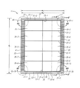
for example, 0.125 inch, whereby leading compressed region 51-2 can be spaced
from
leading edge 27 by a distance of, for example, 0.375 inch. Similarly, trailing
compressed
region 53-2 can be spaced from trailing edge 29 by a length 17 of, for
example, 0.250 inch,
and trailing compressed region 53-1 can be spaced from trailing compressed
region 53-2 by a
length 18 of, for example, 0.125 inch, whereby trailing compressed region 53-1
can be spaced
from trailing edge 29 by a distance of, for example, 0.375 inch.
[0119] Each of side compressed regions 55-1 through 55-79 can have a
width w7 of,
for example, 0.625 inch, can have a length 19 of, for example, 0.03 inch, can
be spaced from
first longitudinal edge 23 by width w5 of, for example, 0.063 inch, and can be
spaced from
longitudinally-extending line 31-1 by a width w8 of, for example, 0.063 inch.
In addition,
side compressed region 55-1 can be spaced from leading compressed region 51-2
by a length
110 of, for example, 0.250 inch, side compressed region 55-79 can be spaced
from trailing
compressed region 53-1 by a length 1i of, for example, 0.250 inch, and each of
side
compressed regions 55-1 through 55-79 can be evenly spaced apart from one
another by a
length 112 of, for example, 0.125 inch. Similarly, each of side compressed
regions 57-1
through 57-79 can have a width w9 of, for example, 0.625 inch, can have a
length 113 of, for
example, 0.03 inch, can be spaced from second longitudinal edge 25 by width w6
of, for
example, 0.063 inch, and can be spaced from longitudinally-extending line 31-3
by a width
w10 of, for example, 0.063 inch. In addition, side compressed region 57-1 can
be spaced from
leading compressed region 51-2 by a length 114 of, for example, 0.250 inch,
side compressed
region 57-79 can be spaced from trailing compressed region 53-1 by a length
115 of, for
example, 0.250 inch, and each of side compressed regions 57-1 through 57-79
can be evenly
spaced apart from one another by a length 116 of, for example, 0.125 inch.
[0120] More generally, the length 14 of each of leading compressed
regions 51-1 and
51-2 and trailing compressed regions 53-1 and 53-2 can be in the range of, but
is not limited
-18-
CA 02899379 2015-04-17
WO 2014/062234
PCT/US2013/036026
1 to, about 0.030 inch to about 0.039 inch. In addition, the width w4 of
each of leading
compressed regions 51-1 and 51-2 and trailing compressed regions 53-1 and 53-2
can be less
than the width wi of sheet construction 11 by an amount in the range of, but
not limited to,
from 0 inch to about 0.158 inch, more specifically about 0.040 inch to about
0.158 inch. In
other words, the width w5 separating each of leading compressed regions 51-1
and 51-2 and
trailing compressed regions 53-1 and 53-2 from first longitudinal edge 23 and
the width w6
separating each of leading compressed regions 51-1 and 51-2 and trailing
compressed regions
53-1 and 53-2 from second longitudinal edge 25 can be in the range of, but is
not limited to, 0
inch to about 0.079 inch, more specifically about 0.020 inch to about 0.079
inch. Moreover,
each of leading compressed regions 51-1 and 51-2 and trailing compressed
regions 53-1 and
53-2 can be compressed to a depth d1 (see Fig. 2) of about 85 microns (3.35
mils) to about
110 microns (4.33 mils), which can be about 24% to about 35% of the total
caliper of sheet
construction 11.
101211 In addition, the length 19 of each of side compressed regions 55-1
through 55-
79 and the length 113 of each of side compressed regions 57-1 through 57-79
can be in the
range of, but is not limited to, about 0.030 inch to about 0.039 inch. In
addition, each of side
compressed regions 55-1 through 55-79 can be spaced apart from first
longitudinal edge 23
by a width w5 that can be in the range of, but is not limited to, 0 inch to
about 0.079 inch,
more specifically about 0.020 inch to about 0.079 inch, and can be spaced
apart from
longitudinally-extending line 31-1 by a width w8 that can be in the range of,
but is not limited
to, 0 inch to about 0.079 inch, more specifically about 0.020 inch to about
0.079 inch.
Similarly, each of side compressed regions 57-1 through 57-79 can be spaced
apart from
second longitudinal edge 25 by a width w6 that can be in the range of, but is
not limited to, 0
inch to about 0.079 inch, more specifically about 0.020 inch to about 0.079
inch, and can be
spaced apart from longitudinally-extending line 31-3 by a width w10 that can
be in the range
of, but is not limited to, 0 inch to about 0.079 inch, more specifically about
0.020 inch to
about 0.079 inch. In addition, each of side compressed regions 55-1 through 55-
79 and 57-1
through 57-79 can be compressed to a depth d1 (see Fig. 2) of about 20 microns
(0.787 mils)
to about 110 microns (3.35 mils), which can be about 5% to about 35% of the
total caliper of
sheet construction 11.
[0122] Without wishing to be limited to any particular theory behind
the invention, it
is believed that the one or more compressed regions in leading margin 37 and
trailing margin
39, which compressed regions are exemplified in the present embodiment by
leading
compressed regions 51-1 and 51-2 and trailing compressed regions 53-1 and 53-
2, can serve
to decrease the stiffness of sheet construction 11 in the direction along
first longitudinal edge
23 and second longitudinal edge 25, i.e., along length l. In particular, it is
believed that, by
-19-
CA 02899379 2015-04-17
WO 2014/062234
PCT/US2013/036026
1 including leading compressed regions 51-1 and 51-2 in leading margin 37,
one can decrease
the force needed to bend sheet construction 11, at laterally-extending line 33-
1, around the
internal bends of a printing device by about 24% to about 38%. Such a
reduction in force is
believed to reduce the incidence of "start of print off-registration" errors.
This is believed to
be because the increased flexibility of sheet construction 11 along its length
l, attributable at
least in part to leading compressed regions 51-1 and 51-2 and trailing
compressed regions 53-
1 and 53-2, enables sheet construction 11 to bend more easily through the
tortuous path of a
printing device.
[0123] In addition, without wishing to be limited to any particular theory
behind the
invention, it is believed that side compressed regions 55-1 through 55-79
and/or side
compressed regions 57-1 through 57-79 enable the rollers inside a printing
device to better
engage sheet construction 1 1 , thereby allowing more continuous indexing of
sheet
construction 11 through the printing device. This may be because the side
compressed
regions allow the printing device to better frictionally engage the sheet
construction as it is
being fed through the printing device.
[0124] It should be understood that the present embodiment discloses
an exemplary
number and arrangement of leading compressed regions 51-1 and 51-2, trailing
compressed
regions 53-1 and 53-2, and side compressed regions 55-1 through 55-79 and 57-1
through 57-
79; consequently, the number of leading compressed regions 51-1 and 51-2,
trailing
compressed regions 53-1 and 53-2, and side compressed regions 55-1 through 55-
79 and 57-1
through 57-79 can be increased or decreased, and the dimensions and placement
of leading
compressed regions 51-1 and 51-2, trailing compressed regions 53-1 and 53-2,
and side
compressed regions 55-1 through 55-79 and 57-1 through 57-79 can be modified.
Notwithstanding the above, it is believed that sheet construction 11 can
include, for example,
from twenty-six to one hundred twenty compressed regions in one or both of
first side margin
41 and second side margin 43 and can include, for example, from one to four
compressed
regions in one or both of leading margin 37 and trailing margin 39.
[0125] Referring now to Fig. 5, there is shown a flowchart,
schematically depicting
one embodiment of a method for making sheet construction 11, the method being
represented
generally by reference numeral 111. Method 111 can begin in a step 112-1 with
the
provision of a roll of first material 13. As noted above, first material 13
can be a single layer
or a multilayer structure. Examples of single layer materials that can be used
as first material
13 can include certain paper materials and certain polymer films. Examples of
such paper
materials can include a sheet of cardstock, such as a sheet of 70-pound
cardstock, and a sheet
of label stock. Examples of such polymer films can include an oriented
polyolefin film, a
-20-
CA 02899379 2015-04-17
WO 2014/062234
PCT/US2013/036026
1 polyester film, and a polyurethane film. Examples of multi-layer
constructions can include,
for example, coated papers, laminated papers, coated polymer films, laminated
polymer
films, and combinations thereof.
[0126] Method 111 can then continue in a step 112-2 with the application
of second
material 15 to second major surface 19 of first material 13 to foul' a
composite roll. As noted
above, second material 15 can consist of a single layer or can include a multi-
layer
construction. Examples of materials suitable for use as second material 15 can
include coated
or uncoated polymers, such polymers including polymethyl pentene, polyolefins
(such as
polypropylene, polyethylenes, and copolymers of propylene and ethylene),
polyesters,
polymethyl methacrylate, polystyrene, and compatible mixtures thereof A
particular
example of a suitable polymer can be poly-4-methyl-1 -pentene. Additional
examples of
materials suitable for use as second material 15 can be found in previously
incorporated U.S.
Patent Application Publication No. US 2003/0148056 Al in connection with the
discussion
therein of carrier material 134. Where second material 15 is a polymer, such
as poly-4-
methyl-l-pentene or a similar substance, the application of second material 15
to first
material 13 can be by extrusion. This allows second material 15 to be coupled
to first
material 13 without requiring an adhesive layer therebetween.
[0127] Method 111 can then continue in a step 112-3 with the formation of
longitudinally-extending lines 31-1 through 31-3 and laterally-extending lines
33-1 through
33-6 in the composite roll. The formation of longitudinally-extending lines 31-
1 through 31-
3 and laterally-extending lines 33-1 through 33-6 can be achieved, for
example, by die-
cutting and preferably involves cutting through first material 13 from first
major surface 17
without cutting through second material 15. Method 111 can then continue in a
step 112-4
with the formation of leading compressed regions 51-1 and 51-2, trailing
compressed regions
53-1 and 53-2, and side compressed regions 55-1 through 55-79 and 57-1 through
57-79 in
the composite roll. The formation of leading compressed regions 51-1 and 51-2,
trailing
compressed regions 53-1 and 53-2, and side compressed regions 55-1 through 55-
79 and 57-1
through 57-79 can be performed by pressing a scoring roller having protrusions
that are
complementary in shape to the compressed regions one wishes to create against
first major
surface 17 of first material 13. It should be understood that, although step
112-3 is described
above as taking place before step 112-4, the order of these two steps could be
reversed.
Method 111 can then conclude in a step 112-5 with the cutting of the composite
roll into
sheets, preferably of standard paper size.
-21-
CA 02899379 2015-04-17
WO 2014/062234
PCT/US2013/036026
1 [0128] Referring now to Fig. 6, there is schematically shown an
apparatus that can be
used to make sheet construction 11, the apparatus being represented by
reference numeral
151.
[0129] Apparatus 151 can include a supply roll 153 of first material 13,
which supply
roll 153 can be unwound from a reel 159. Apparatus 151 can further include an
extruder 161
equipped with a die head 163. First material 13 can be fed past die head 163
so that second
material 15 can be continuously extruded onto second major surface 19 of first
material 13,
thereby forming a composite material 165 of first material 13 and second
material 15.
Apparatus 151 can further include a media defining station 167 through which
composite
material 165 can be passed so that individual print-receptive media 35-1
through 35-10 can
be defined in composite material 165, thereby yielding a first modified
composite material
169. Station 167 can include the combination of a cylindrical die 171 having
knife elements
173 arranged on its periphery and a smooth anvil roller 175.
[0130] Apparatus 151 can further include a compressing station 177
through which
first modified composite material 169 can be passed so that leading compressed
regions 51-1
and 51-2, trailing compressed regions 53-1 and 53-2, and side compressed
regions 55-1
through 55-79 and 57-1 through 57-79 can be formed in first modified composite
material
169, thereby yielding a second modified composite material 179. Station 177
can include the
combination of a scoring roller 181 (also shown in Fig. 7 and including a
plurality of longer
protrusions 182, which can be used, for example, to form leading compressed
regions 51-1
and 51-2 and trailing compressed regions 53-1 and 53-2, and a plurality of
shorter protrusions
184, which can be used, for example, to form side compressed regions 55-1
through 55-79
and 57-1 through 57-79) and a smooth anvil roller 183. Apparatus 151 can
further include a
printing station 185 through which second modified composite material 179 can
be passed so
that indicia (e.g., trademarks, instructions, etc.) can be imprinted on first
material 13 and/or
second material 15, thereby yielding a third modified composite material 187.
Apparatus 151
can further include a sheeting station 189 for cutting third modified
composite material 187
into standard paper-sized sheets, thereby yielding sheet construction 11.
Apparatus 151 can
further include a packaging station 191 for packaging one or more sheet
constructions 11.
[0131] Referring now to Fig. 8, there is shown a flowchart,
schematically depicting
one embodiment of a method for using sheet construction 11, the method being
represented
generally by reference numeral 211. Method 211 can begin in a step 212-1 with
the passing
of sheet construction 11 through a printing device 213 (see also Fig. 9(a)),
whereby indicia
can be printed on one or more of print-receptive media 35-1 through 35-10.
Because of the
presence of leading compressed regions 51-1 and 51-2, trailing compressed
regions 53-1 and
-22-
CA 02899379 2015-04-17
WO 2014/062234
PCT/US2013/036026
1 53-2, and side compressed regions 55-1 through 55-79 and 57-1 through 57-
79 on sheet
construction 11, the occurrence of "start of print off-registration" errors
can be reduced.
Method 211 can then conclude in a step 212-2 with the separation of one or
more of print-
receptive media 35-1 through 35-10 from one another and from the remainder of
sheet
construction 11, one or more of said print-receptive media 35-1 through 35-10
preferably
bearing printed indicia thereon. Such separation can be achieved, for example,
by bending
sheet construction 11 until second material 15 breaks in an area underlying
one or more of
longitudinally-extending lines 31-1 through 31-3 and laterally-extending lines
33-1 through
33-6 (see also Fig. 9(b)).
[01321 Referring now to Figs. 10(a), 10(b), and 11, there are shown
various views of
a second embodiment of a sheet construction according to the present
invention, the sheet
construction being represented generally by reference numeral 251.
[01331 Sheet construction 251 can be similar in most respects to sheet
construction
11. A principal difference between sheet construction 251 and sheet
construction 11 can be
that, whereas sheet construction 11 can include compressed regions 51-1, 51-2,
53-1, 53-2,
55-1 through 55-79, and 57-1 through 57-79 that appear in first major surface
17 of first
material 13 but do not appear as protrusions in second major surface 22 of
second material
15, sheet construction 251 can include compressed regions 253-1, 253-2, 255-1,
255-2, 257-1
through 257-79, and 259-1 through 259-79 in first major surface 17 of first
material 13 and
protrusions 252-1, 252-2, 254-1, 254-2, 256-1 through 256-79, and 258-1
through 258-79 in
second major surface 22 of second material 15. Compressed regions 253-1, 253-
2, 255-1,
255-2, 257-1 through 257-79, and 259-1 through 259-79 can be made by a process
that is
essentially identical to that described above for making compressed regions 51-
1, 51-2, 53-1,
53-2, 55-1 through 55-79, and 57-1 through 57-79. It is believed that whether
or not such a
process results in compressed regions like compressed regions 51-1, 51-2, 53-
1, 53-2, 55-1
through 55-79, and 57-1 through 57-79, which do not exhibit corresponding
protrusions in
second major surface 22 of second material 15, or in compressed regions like
compressed
regions 253-1, 253-2, 255-1, 255-2, 257-1 through 257-79, and 259-1 through
259-79, which
do exhibit protrusions 252-1, 252-2, 254-1, 254-2, 256-1 through 256-79, and
258-1 through
258-79 in second major surface 22 of second material 15, can be affected, to
some degree, by
the amount of support provided to second major surface 22 of second material
15 as the
regions are being compressed. In other words, when comparatively lesser
support is provided
to second major surface 22 of second material 15 as compression takes place,
compressed
regions resembling compressed regions 253-1, 253-2, 255-1, 255-2, 257-1
through 257-79,
and 259-1 through 259-79 and protrusions 252-1, 252-2, 254-1, 254-2, 256-1
through 256-79,
and 258-1 through 258-79 can tend to be formed whereas, when comparatively
greater
-23-
CA 02899379 2015-04-17
WO 2014/062234
PCT/US2013/036026
1 support is provided to second major surface 22 of second material 15 as
compression takes
place, compressed regions resembling compressed regions 51-1, 51-2, 53-1, 53-
2, 55-1
through 55-79, and 57-1 through 57-79 can tend to be formed.
[0134] Sheet construction 251 can be used in the same fashion as sheet
construction
11.
[0135] A partial section view of a first alternate embodiment to
sheet construction
251 is shown in Fig. 12 as sheet construction 260. Sheet construction 260,
which includes
compressed regions 260-1 and 260-2 and protrusions 261-1 and 261-2, can be
formed by
modifying apparatus 151 of Fig. 6 by replacing compressing station 177 with a
compressing
station 262, which is shown in Fig. 13. Compressing station 262 can include
the combination
of a first scoring roller 181-1, a first anvil roller 263-1, a second scoring
roller 181-2, and a
second anvil roller 263-2. First scoring roller 181-1 and second scoring
roller 181-2 can be
provided with protrusions 264, and first anvil roller 263-1 and second anvil
roller 263-2 can
be provided with complementary recesses 265. Second scoring roller 181-2 and
second anvil
roller 263-2 can be indexed relative to first scoring roller 181-1 and first
anvil roller 263-1 to
produce the alternating pattern of compressed regions 260-1 and 260-2 and
protrusions 261-1
and 261-2 shown in Fig. 12.
[01361 A partial section view of a second alternate embodiment to
sheet construction
251 is shown in Fig. 14 as sheet construction 266. Sheet construction 266,
which includes
compressed regions 267-1 and 267-2 compressed from opposite surfaces 268-1 and
268-2,
respectively, of sheet construction 266, can be formed by modifying apparatus
151 of Fig. 6
by replacing compressing station 177 with a compressing station 269, which is
shown in Fig.
15. Compressing station 269 can include a pair of scoring rollers 270-1 and
270-2 which are
aligned with one another to produce the symmetric pattern of compressed
regions 267-1 and
267-2 shown in Fig. 14.
[0137] Referring now to Figs. 16(a) through 16(f), as well as Fig. 17,
there are shown
various views of a fifth embodiment of a sheet construction according to the
present
invention, the sheet construction being represented generally by reference
numeral 271.
[0138] Sheet construction 271, which can be similar in many respects
to sheet
construction 11, can include a first material 273 and a second material 275.
First material
273 can include a substrate 277 having a first major surface 279 and an
opposed second
major surface 281. Substrate 277 can consist of a single layer or can include
a multi-layer
construction. Examples of single layer materials that can be used as substrate
277 can
-24-
CA 02899379 2015-04-17
WO 2014/062234
PCT/US2013/036026
1 include certain paper materials and certain polymer films. Examples of
such paper materials
can include a sheet of cardstock, such as a sheet of 70-pound cardstock, and a
sheet of label
stock. Examples of such polymer films can include an oriented polyolefin film,
a polyester
film, and a polyurethane film. Examples of multi-layer constructions can
include, for
example, coated papers, laminated papers, coated polymer films, laminated
polymer films,
and combinations thereof.
[0139] First material 273 can further include a print-receptive
coating 283 disposed
directly on first major surface 279 of substrate 277. Print-receptive coating
283 can be any
one or more print-receptive materials known to those skilled in the art for
use in receiving
markings made by hand or by a printing device. For example, where one wishes
to make
dry-erase markings on first material 273, print-receptive coating 283 can
include a
conventional dry-erase film, such as a polyethylene terephthalate (PET) film,
a polypropylene
film, or the like. Additional examples of materials suitable for use as print-
receptive coating
283 can be found in previously incorporated U.S. Patent Application
Publication No, US
2003/0148056 Al in connection with the discussion therein of top material 130.
[0140] Second material 275, which can be identical in construction
and composition
to second material 15 of sheet construction 11, can be shaped to include a
first major surface
285 and an opposed second major surface 287. Second material 275 can be joined
directly to
first material 273, with first major surface 285 of second material 275 fixed
to and in direct
contact with second major surface 281 of substrate 277. First material 273 and
second
material 275 can be coextensive so that the entirety of second major surface
281 of substrate
277 can be covered by first major surface 285 of second material 275 and so
that the entirety
of first major surface 285 of second material 275 can be covered by second
major surface 281
of substrate 277. In this manner, first material 273 and second material 275
can jointly form
a generally rectangular sheet-like structure including a first longitudinal
edge 289, a second
longitudinal edge 291, a leading edge 293, and a trailing edge 295, with print-
receptive
coating 283 of first material 273 forming a first exposed surface for the
structure and with
second major surface 287 of second material 275 forming an opposed second
exposed surface
for the structure.
[0141] Second material 275 can be applied directly to first material
273, for example,
by extrusion. Second major surface 287 of second material 275 can be
roughened, for
example, in the manner described in previously incorporated U.S. Patent
Application
Publication No. US 2003/0148056 Al, so that print-receptive coating 283 of
first material
273 and second major surface 287 of second material 275 can have similar
haptic properties,
i.e., feel similar to the touch. In addition, the receptivity of second major
surface 287 of
-25-
CA 02899379 2015-04-17
WO 2014/062234
PCT/US2013/036026
1 second material 275 to markings of the type that can be made manually
and/or with a printing
device can be improved by such roughening.
[0142] First material 273 and second material 275 can have a combined
thickness of
at least about 4 mils and, more specifically, can have a combined thickness of
about 4 mils to
about 14 mils, or about 4 mils to about 7 mils in the case of the sheet
construction including
label stock, or about 8 mils to about 14 mils in the case of the sheet
construction including
card stock.
[0143] Sheet construction 271 can further include a plurality of lines for
defining one
or more smaller-size print-receptive media. Such defining lines can be, for
example, die-cut
lines, partial die-cut lines, perforated lines including microperforated
lines, lines of cuts and
ties, etched lines, and lines made by other techniques known in the art. As
exemplified by the
present embodiment, the aforementioned defining lines can include three
parallel
longitudinally-extending lines 297-1 through 297-3, and six parallel laterally-
extending lines
299-1 through 299-6. Longitudinally-extending lines 297-1 through 297-3 and
laterally-
extending lines 299-1 through 299-6, which can extend partially or completely
through first
material 273 and also partially but not completely through second material
275, can be
arranged to define an array of ten print-receptive media 301-1 through 301-10
and a frame
302 surrounding print-receptive media 301-1 through 301-10. Frame 302 can
include (i) a
leading margin 303 extending from first longitudinal edge 289 to second
longitudinal edge
291 and bounded by first longitudinal edge 289, second longitudinal edge 291,
leading edge
293, and laterally-extending line 299-1, (ii) a trailing margin 304 extending
from first
longitudinal edge 289 to second longitudinal edge 291 and bounded by first
longitudinal edge
289, second longitudinal edge 291, trailing edge 295, and laterally-extending
line 299-6, (iii)
a first side margin 305 bounded by first longitudinal edge 289, longitudinally-
extending line
297-1, leading margin 303, and trailing margin 304, and (iv) a second side
margin 306
bounded by second longitudinal edge 291, longitudinally-extending line 297-3,
leading
margin 303, and trailing margin 304.
[0144] Longitudinally-extending lines 297-1 through 297-3 and
laterally-extending
lines 299-1 through 299-6 can be formed in the same manner as, and can be
shaped and
dimensioned similarly to, longitudinally-extending lines 31-1 through 31-3 and
laterally-
extending lines 33-1 through 33-6, respectively, of sheet construction 11.
[0145] It should be understood that the number of longitudinally-
extending lines 297-
] through 297-3, the number of laterally-extending lines 299-1 through 299-6,
and the
arrangement of longitudinally-extending lines 297-1 through 297-3 and
laterally-extending
-26-
CA 02899379 2015-04-17
WO 2014/062234
PCT/US2013/036026
1 lines 299-1 through 299-6 in the present embodiment are merely exemplary;
consequently,
the numbers of longitudinally-extending lines 297-1 through 297-3 and
laterally-extending
lines 299-1 through 299-6 can be increased or decreased and their arrangement
can be
modified.
[0146] Sheet construction 271 can further include two leading
compressed regions
307-1 and 307-2 disposed within leading margin 303, two trailing compressed
regions 308-1
and 308-2 disposed within trailing margin 304, seventy-nine side compressed
regions 309-1
through 309-79 disposed within first side margin 305, and seventy-nine side
compressed
regions 310-1 through 310-79 disposed within second side margin 306. The
arrangement and
dimensions of leading compressed regions 307-1 and 307-2, trailing compressed
regions 308-
1 and 308-2, and side compressed regions 309-1 through 309-79 and 310-1
through 310-79
can be similar to those of leading compressed regions 51-1 and 51-2, trailing
compressed
regions 53-1 and 53-2, and side compressed regions 55-1 through 55-79 and 57-1
through 57-
79, respectively, of sheet construction 11 or to those of leading compressed
regions 253-1 and
253-2, trailing compressed regions 255-1 and 255-2, and side compressed
regions 257-1
through 257-79 and 259-1 through 259-79, respectively, of sheet construction
251.
[0147] It should be understood that the number and arrangement of
leading
compressed regions 307-1 and 307-2, trailing compressed regions 308-1 and 308-
2, and side
compressed regions 309-1 through 309-79 and 310-1 through 310-79 in sheet
construction
271 is merely exemplary; consequently, the number of leading compressed
regions 307-1 and
308-1, trailing compressed regions 308-1 and 308-2, and side compressed
regions 309-1
through 309-79 and 310-1 through 310-79 in sheet construction 271 can be
increased or
decreased, and the dimensions and placement of leading compressed regions 307-
1 and 308-
1, trailing compressed regions 308-1 and 308-2, and side compressed regions
309-1 through
309-79 and 310-1 through 310-79 can be modified. Notwithstanding the above, it
is believed
that sheet construction 271 can include, for example, from twenty-six to one
hundred twenty
compression regions in one or both of first side margin 305 and second side
margin 306 and
can include, for example, from one to four compressed regions in one or both
of leading
margin 303 and trailing margin 304.
[0148] Sheet construction 271 can be made and used similarly to sheet
construction
11.
[0149] Referring now to Fig. 18, there is a front view of a sixth
embodiment of a
sheet construction according to the present invention, the sheet construction
being
represented generally by reference numeral 311.
-27-
CA 02899379 2015-04-17
WO 2014/062234
PCT/US2013/036026
1
[0150] Sheet construction 311 can be similar in most respects to
sheet construction
11. One difference between the two sheet constructions can be that, whereas
sheet
construction 11 can include leading compressed regions 51-1 and 51-2 in
leading margin 37
that can have a generally straight profile and can also include trailing
compressed regions 53-
1 and 53-2 in trailing margin 39 that can have a generally straight profile,
sheet construction
311 can include leading compressed regions 313-1 through 313-3 in leading
margin 37 that
can have a generally arcuate or wavy profile and can also include trailing
compressed regions
313-4 through 313-6 in trailing margin 39 that can have a generally arcuate or
wavy profile.
Leading compressed regions 313-1 through 313-3 and trailing compressed regions
313-4
through 313-6 can also differ from leading compressed regions 51-1 and 51-2
and trailing
compressed regions 53-1 and 53-2 in that leading compressed regions 313-1
through 313-3
and trailing compressed regions 313-4 through 313-6 can extend between
longitudinal edges
23 and 25 whereas leading compressed regions 51-1 and 51-2 and trailing
compressed
regions 53-1 and 53-2 can be spaced from longitudinal edges 23 and 25.
Alternatively,
leading compressed regions 313-1 through 313-3 and trailing compressed regions
313-4
through 313-6 can be spaced from longitudinal edges 23 and 25 similarly to
leading
compressed regions 51-1 and 51-2 and trailing compressed regions 53-1 and 53-
2. Leading
compressed regions 313-1 through 313-3 and trailing compressed regions 313-4
through 313-
6 can form corresponding protrusions on the rear of sheet construction 311,
similar to those
of sheet construction 251; alternatively, leading compressed regions 313-1
through 313-3 and
trailing compressed regions 313-4 through 313-6 can be devoid of any such
corresponding
protrusions, similar to sheet construction 11.
[0151] Sheet construction 311 can also differ from sheet construction 11 in
that,
whereas sheet construction 11 can include side compressed regions 55-1 through
55-79 and
57-1 through 57-59, sheet construction 311 can omit such compressed regions.
[0152] Sheet construction 311 can be made and used analogously to
sheet
construction 11.
[0153] Referring now to Fig. 19, there is a front view of a seventh
embodiment of a
sheet construction according to the present invention, the sheet construction
being
represented generally by reference numeral 351.
[0154] Sheet construction 351 can be similar in most respects to
sheet construction
311. One difference between the two sheet constructions can be that, whereas
sheet
construction 311 can omit compressed regions in side margins 41 and 43, sheet
construction
-28-
CA 02899379 2015-04-17
WO 2014/062234
PCT/US2013/036026
1 351 can include side compressed regions 353-1 through 353-79 in first
side margin 41 and
can include side compressed regions 355-1 through 355-79 in second side margin
43. Side
compressed regions 353-1 through 353-79 and 355-1 through 355-79 can be
similar to side
compressed regions 55-1 through 55-79 and 57-1 through 57-79, respectively, of
sheet
construction 11 or can be similar to side compressed regions 257-1 through 257-
79 and 259-1
through 259-79, respectively, of sheet construction 251. Moreover, although
each of side
compressed regions 353-1 through 353-79 and 355-1 through 355-79 is shown as
being
straight, some or all of side compressed regions 353-1 through 353-79 and 355-
1 through
355-79 can be arcuate or wavy.
[0155] Sheet construction 351 can be made and used analogously to
sheet
construction 311.
[0156] Referring now to Figs. 20(a) through 20(f), as well as Figs.
21 and 22, there
are shown various views of a eighth embodiment of a sheet construction made
according to
the present invention, the sheet construction being represented generally by
reference
numeral 411.
[0157] Sheet construction 411 can include a sheet of material 413.
Material 413 can
be a generally rectangular sheet-like structure of a standard paper size
(e.g., letter-size, legal-
size, A4, etc.) and can be shaped to include a first major surface 417, an
opposed second
major surface 419, a first longitudinal edge 423, a second longitudinal edge
425, a leading
edge 427, and a trailing edge 429. One or both of first major surface 417 and
second major
surface 419 can be receptive to markings of the type that can be made manually
and/or with a
printing device. Examples of markings of the type that can be made manually
include, but
are not limited to, hand-drawn pencil markings, hand-drawn pen markings, hand-
drawn
crayon markings, hand-drawn paint markings, hand-drawn dry-erase markings,
hand-drawn
chalk markings, hand-made stampings, including hand-made hot stampings, hand-
made heat-
transfers, and other hand-made markings known to those skilled in the art, as
well as
combinations thereof. Examples of markings of the type that can be made with a
printing
device include, but are not limited to, ink jet printer markings, laser
printer markings,
photocopier markings, and combinations thereof
[0158] Material 413 can consist of a single layer or can include a
multi-layer
construction. Examples of single layer materials that can be used as material
413 can include
certain paper materials and certain polymer films. Examples of such paper
materials can
include a sheet of cardstock, such as a sheet of 70-pound cardstock, and a
sheet of label stock.
Examples of such polymer films can include a film of an oriented polyolefin, a
polyester
-29-
CA 02899379 2015-04-17
WO 2014/062234
PCT/US2013/036026
film, and a polyurethane film. Examples of multi-layer constructions can
include, for
example, coated papers, laminated papers, coated polymer films, laminated
polymer films,
and combinations thereof. If material 413 includes a print-receptive material
coated on one
or both of its major surfaces, such a print-receptive material can be any one
or more print-
receptive materials known to those skilled in the art. For example, where one
wishes to make
dry-erase markings on first major surface 417 of material 413, such a print-
receptive material
can include a conventional dry-erase film, such as a polyethylene
terephthalate (PET) film, a
polypropylene film, or the like. Additional examples of materials suitable for
use as material
413 can be found in previously incorporated U.S. Patent No. 5,993,928 in
connection with
the discussion therein of paper 160.
[01591 Material 413 can have a thickness of at least about 4 mils
and, more
specifically, can have a thickness of about 4 mils to about 14 mils, or about
4 mils to about 7
mils in the case of the sheet construction including label stock, or about 8
mils to about 14
mils in the case of the sheet construction including card stock.
[0160] Sheet construction 411 can further include a plurality of
perforation lines in
material 413 for defining one or more smaller-size print-receptive media. As
exemplified by
the present embodiment, the aforementioned perforation lines can include three
lengthwise
perforation lines 431-1 through 431-3 extending parallel to first longitudinal
edge 423 and
second longitudinal edge 425 and six widthwise perforation lines 433-1 through
433-6
extending parallel to leading edge 427 and trailing edge 429. Lengthwise
perforation lines
431-1 through 431-3 and widthwise perforation lines 433-1 through 433-6 can
together define
ten print-receptive media 437-1 through 437-10. A leading margin 441 can be
bounded by
first longitudinal edge 423, second longitudinal edge 425, leading edge 427,
and widthwise
perforation line 433-1. A trailing margin 443 can be bounded by first
longitudinal edge 423,
second longitudinal edge 425, trailing edge 429, and widthwise perforation
line 433-6. A
first side margin 445 can be bounded by first longitudinal edge 423,
longitudinal line 431-1,
leading margin 441, and trailing margin 443. A second side margin 447 can be
bounded by
second longitudinal edge 425, longitudinal line 431-3, leading margin 441, and
trailing
margin 443.
[0161] It is to be understood that, although lines 431-1 through 431-
3 and lines 433-1
through 433-6 are shown in the present embodiment as perforation lines, which
can include
microperforation lines, such lines need not be perforation lines and can
alternatively be
substantial cut lines, score lines, lines of cuts and ties, or any other type
of defining line other
than a continuous through-cut line.
-30-
CA 02899379 2015-04-17
WO 2014/062234
PCT/US2013/036026
1 [0162] It should be understood that the number of lengthwise
perforation lines 431-1
through 431-3, the number of widthwise perforation lines 433-1 through 433-6,
and the
arrangement, including the length and/or width, of lengthwise perforation
lines 431-1 through
431-3 and widthwise perforation lines 433-1 through 433-6 in the present
embodiment are
merely exemplary; consequently, the numbers of lengthwise perforation lines
431-1 through
431-3 and widthwise perforation lines 433-1 through 433-6 can be increased or
decreased and
their arrangement can be modified. Additionally, the perforations lines can
engage the edges
of construction 411, as shown, or, in other embodiments, the perforation lines
can end before
engaging the edges of construction 411.
[0163] As can be seen, for example, in Figs. 21 and 22, sheet
construction 411 can
further include one or more leading compressed regions 451-1 and 451-2,
trailing compressed
regions 453-1 and 453-2, and side compressed regions 455-1 through 455-79 and
457-1
through 457-79, i.e., regions in which material 413 is compressed to a reduced
thickness.
With respect to the aforementioned one or more compressed regions, the
thickness of
material 413, as measured from first major surface 417 to second major surface
419, can be
reduced by about 5% to about 35% from a non-compressed thickness t3 of, for
example,
about 4 mils to about 14 mils, to a compressed thickness t4 of, for example,
about 2.6 mils to
about 13.3 mils. The one or more compressed regions can be asymmetrically
compressed
relative to first major surface 417 and second major surface 419 and, for
example, can appear
in first major surface 417, either with or without corresponding protrusions
in second major
surface 419. As viewed from the front of sheet construction 411, the one or
more compressed
regions can include straight compressed regions (as shown in Fig. 20(a)),
arcuate compressed
regions (as shown in Fig. 18), or a mixture of straight and arcuate regions
(as shown in Fig.
19). The one or more compressed regions can be positioned in one or more of
leading margin
441, trailing margin 443, first side margin 445, and second side margin 447.
In the present
embodiment, the one or more compressed regions can include leading compressed
regions
451-1 and 451-2 in leading margin 441, trailing compressed regions 453-1 and
453-2 in
trailing margin 443, side compressed regions 455-1 through 455-79 in first
side margin 445,
and side compressed regions 457-1 through 457-79 in second side margin 447.
The
dimensions and layout of leading compressed regions 451-1 and 451-2, trailing
compressed
regions 453-1 and 453-2, and side compressed regions 455-1 through 455-79 and
457-1
through 457-79 can be similar to those of leading compressed regions 51-1 and
51-2, trailing
compressed regions 53-1 and 53-2, and side compressed regions 55-1 through 55-
79 and 57-1
through 57-79, respectively, or can be modified as necessary or desired.
101641 It should be understood that the present embodiment discloses
an exemplary
number and arrangement of leading compressed regions 451-1 and 451-2, trailing
-31-
CA 02899379 2015-04-17
WO 2014/062234
PCT/US2013/036026
1 compressed regions 453-1 and 453-2, and side compressed regions 455-1
through 455-79 and
457-1 through 457-79; consequently, the number of leading compressed regions
451-1 and
451-2, trailing compressed regions 453-1 and 453-2, and side compressed
regions 455-1
through 455-79 and 457-1 through 457-79 can be increased or decreased, and the
dimensions
and placement of leading compressed regions 451-1 and 451-2, trailing
compressed regions
453-1 and 453-2, and side compressed regions 455-1 through 455-79 and 457-1
through 457-
79 can be modified. Notwithstanding the above, it is believed that sheet
construction 411 can
include, for example, from twenty-six to one hundred twenty compressed regions
in one or
both of first side margin 445 and second side margin 447 and can include, for
example, from
one to four compressed regions in one or both of side margin 441 and side
margin 443.
[0165] Referring now to Fig. 23, there is shown a flowchart,
schematically depicting
one embodiment of a method for making sheet construction 411, the method being
represented generally by reference numeral 511. Method 511 can begin in a step
512-1 with
the provision of a roll of material 413. As noted above, material 413 can be a
single layer or
a multilayer structure. Examples of single layer materials that can be used as
material 413
can include certain paper materials and certain polymer films. Examples of
such paper
materials can include a sheet of cardstock, such as a sheet of 70-pound
cardstock, and a sheet
of label stock. Examples of such polymer films can include an oriented
polyolefin film, a
polyester film, and a polyurethane film. Examples of multi-layer constructions
can include,
for example, coated papers, laminated papers, coated polymer films, laminated
polymer
films, and combinations thereof
[0166] Method 511 can then continue in a step 512-2 with the
foimation of
lengthwise perforation lines 431-1 through 431-3 and widthwise perforation
lines 433-1
through 433-6 in material 413. Method 511 can then continue in a step 512-3
with the
formation of leading compressed regions 451-1 and 451-2, trailing compressed
regions 453-1
and 453-2, and side compressed regions 455-1 through 455-79 and 457-1 through
457-79 in
material 413. The formation of leading compressed regions 451-1 and 451-2,
trailing
compressed regions 453-1 and 453-2, and side compressed regions 455-1 through
455-79 and
457-1 through 457-79 can be perfoimed by pressing a scoring roller having
protrusions that
are complementary in shape to the compressed regions one wishes to create
against first
major surface 417 of material 413. It should be understood that, although step
512-2 is
described above as taking place before step 512-3, the order of these two
steps could be
reversed. Method 511 can then conclude in a step 512-4 with the cutting of the
perforated
and compressed roll into sheets, preferably of standard paper size.
-32-
CA 02899379 2015-04-17
WO 2014/062234
PCT/US2013/036026
1 [0167] Referring now to Fig. 24, there is schematically shown an
apparatus that can
be used to make sheet construction 411, the apparatus being represented by
reference numeral
551.
[0168] Apparatus 551 can include a supply roll 553 of material 413, which
supply roll
553 can be unwound from a reel 559. Apparatus 551 can further include a media
defining
station 567 through which material 413 can be passed so that individual media
437-1 through
437-10 can be defined in material 413, thereby yielding a first modified
material 569. Station
567 can include the combination of a cylindrical die 571 having perforating
elements 573
arranged on its periphery and a smooth anvil roller 575.
[0169] Apparatus 551 can further include a compressing station 577
through which
material 569 can be passed so that leading compressed regions 451-1 and 451-2,
trailing
compressed regions 453-1 and 453-2, and side compressed regions 455-1 through
455-79 and
457-1 through 457-79 can be formed in material 569, thereby yielding a second
modified
material 579. Station 577 can include the combination of a scoring roller 581
and a smooth
anvil roller 583. Apparatus 551 can further include a printing station 585
through which
material 579 can be passed so that indicia (e.g., trademarks, instructions,
etc.) can be
imprinted on one or both major surfaces of material 413, thereby yielding a
third modified
material 587. Apparatus 551 can further include a sheeting station 589 for
cutting material
587 into standard paper-sized sheets, thereby yielding sheet construction 411.
Apparatus 551
can further include a packaging station 591 for packaging one or more sheet
constructions
411.
[0170] Referring now to Fig. 25, there is shown a flowchart, schematically
depicting
one embodiment of a method for using sheet construction 411, the method being
represented
generally by reference numeral 611. Method 611 can begin in a step 612-1 with
the passing
of sheet construction 411 through a printing device 613 (see also Fig. 26(a)),
whereby indicia
can be printed on one or more of print-receptive media 437-1 through 437-10.
Because of the
presence of leading compressed regions 451-1 and 451-2, trailing compressed
regions 453-1
and 453-2, and side compressed regions 455-1 through 455-79 and 457-1 through
457-79 on
sheet construction 411, the occurrence of "start of print off-registration"
errors can be
reduced. Method 611 can then conclude in a step 612-2 with the separation of
one or more of
print-receptive media 437-1 through 437-10 from one another and from the
remainder of
sheet construction 411 (see also Fig. 26(b)), one or more of said print-
receptive media 437-1
through 437-10 preferably bearing printed indicia thereon. Such separation can
be achieved,
for example, by tearing sheet construction 411 along one or more appropriate
lengthwise
perforation lines 431-1 through 431-3 and widthwise perforation lines 433-1
through 433-6.
-33-
CA 02899379 2015-04-17
WO 2014/062234
PCT/US2013/036026
1
[0171] Referring now to Figs. 27(a) through 27(f), as well as Figs.
28 and 29, there
are shown various views of a ninth embodiment of a sheet construction made
according to the
present invention, the sheet construction being represented generally by
reference numeral
711.
[0172] Sheet construction 711 can include a first material 713 and a
second material
715. First material 713 can be a generally rectangular sheet-like structure of
a standard paper
size (e.g., letter-size, legal-size, A4, etc.) and can be shaped to include a
first major surface
717 and an opposed second major surface 719. First major surface 717 can be
receptive to
markings of the type that can be made manually and/or with a printing device.
Examples of
markings of the type that can be made manually include, but are not limited
to, hand-drawn
pencil markings, hand-drawn pen markings, hand-drawn crayon markings, hand-
drawn paint
markings, hand-drawn dry-erase markings, hand-drawn chalk markings, hand-made
stampings, including hand-made hot stampings, hand-made heat-transfers, and
other hand-
made markings known to those skilled in the art, as well as combinations
thereof Examples
of markings of the type that can be made with a printing device include, but
are not limited
to, ink jet printer markings, laser printer markings, photocopier markings,
and combinations
thereof
10173] First material 713 can consist of a single layer or can
include a multi-layer
construction. Examples of single layer materials that can be used as material
713 can include
certain paper materials and certain polymer films. Examples of such paper
materials can
include a sheet of adhesive label facestock. Examples of such polymer films
can include an
oriented polyolefin film, a polyester film, and a polyurethane film. Examples
of multi-layer
constructions can include, for example, coated papers, laminated papers,
coated polymer
films, laminated polymer films, and combinations thereof.
[0174] Second material 715 can be a pressure-sensitive adhesive
applied to second
major surface 719 of first material 713. In one embodiment, second material
715 can be
applied to the entirety of second major surface 719 of first material 713 so
as to form a
continuous coating thereon. In another embodiment, second material 715 can be
pattern-
coated onto predetermined portions of second major surface 719. The
combination of first
material 713 and second material 715 can comprise an adhesive assembly 720,
which can be
used as an adhesive-backed label. Depending on the particular intended use of
adhesive
assembly 720, a suitable adhesive can be selected for use as second material
715. Examples
of adhesives that can be suitable can include pressure-sensitive adhesives,
such as permanent
adhesives, removable adhesives, ultraremovable adhesives, hot-melt adhesives,
acrylic
-34..
CA 02899379 2015-04-17
WO 2014/062234
PCT/US2013/036026
1 adhesives, and rubber-based adhesives. Suitable pressure-sensitive
adhesives can include, for
example, S-490 adhesive from Avery Dennison Corporation (Pasadena, CA) and AT-
1
adhesive from Avery Dennison Corporation (Pasadena, CA). Adhesive assembly 720
can be
a generally rectangular sheet-like structure including a first longitudinal
edge 712, a second
longitudinal edge 714, a leading edge 716, and a trailing edge 718.
[0175] Sheet construction 711 can further include a third material
721. Third material
721 can include a carrier 723, which can be, for example, a sheet of paper,
and can also
include a release coating 725, which can be, for example, a silicone-based
release coating
applied to a first major surface 727 of carrier 723. Second material 715 can
be positioned in
direct contact with release coating 725. Third material 721 can be slightly
oversized relative
to adhesive assembly 720 so that first longitudinal edge 712, second
longitudinal edge 714,
leading edge 716, and trailing edge 718 of adhesive assembly 720 are spaced
slightly
inwardly of a first longitudinal edge 733, a second longitudinal edge 735, a
leading edge 737,
and a trailing edge 739, respectively, of third material 721. For example,
first longitudinal
edge 712 of adhesive assembly 720 can be spaced inwardly relative to first
longitudinal edge
733 of third material 721 by about 0.094 inch, second longitudinal edge 714 of
adhesive
assembly 720 can be spaced inwardly relative to second longitudinal edge 735
of third
material 721 by about 0.094 inch, leading edge 716 of adhesive assembly 720
can be spaced
inwardly relative to leading edge 737 of third material 721 by about 0.04
inch, and trailing
edge 718 of adhesive assembly 720 can be spaced inwardly relative to trailing
edge 739 of
third material 721 by about 0.04 inch.
101761 Sheet construction 711 can further include a plurality of
lines defining one or
more smaller-size print-receptive media. Such defining lines can be, for
example, die-cut
lines, partial die-cut lines, perforated lines including microperforated
lines, lines of cuts and
ties, etched lines, and lines made by other techniques known in the art. As
exemplified by the
present embodiment, the aforementioned defining lines can include six
circumscribing lines
745-1 through 745-6 defining six generally rectangular print-receptive media
749-1 through
749-6, respectively, each in the foim of an adhesive-backed label. A leading
margin 751 in
adhesive assembly 720 can extend from first longitudinal edge 712 to second
longitudinal
edge 714 and can be bounded by first longitudinal edge 712, second
longitudinal edge 714,
leading edge 716, and print-receptive media 749-1 and 749-2. A trailing margin
753 in
adhesive assembly 720 can extend from first longitudinal edge 712 to second
longitudinal
edge 714 and can be bounded by first longitudinal edge 712, second
longitudinal edge 714,
trailing edge 718, and print-receptive media 749-5 and 749-6. A first side
margin 755 in
adhesive assembly 720 can be bounded by first longitudinal edge 712, leading
margin 751,
trailing margin 753, and print-receptive media 749-1, 749-3, and 749-5. A
second side
-35-
CA 02899379 2015-04-17
WO 2014/062234
PCT/US2013/036026
1 margin 757 in adhesive assembly 720 can be bounded by second longitudinal
edge 714,
leading margin 751, trailing margin 753, and print-receptive media 749-2, 749-
4, and 749-6.
[0177] Circumscribing lines 741-1 through 741-6 can be formed, for
example, by die-
cutting or rotary knives and can extend entirely through adhesive assembly 720
but in some
embodiments do not extend through third material 721.
[0178] It should be understood that the number, size, shape, and
arrangement of print-
receptive media 749-1 through 749-6 in the present embodiment are merely
exemplary;
consequently, the number of print-receptive media 749-1 through 749-6 can be
increased or
decreased, and the size, shape, and arrangement of print-receptive media 749-1
through 749-6
can be modified. For example, sheet construction 711 can be modified to
include as few as
one print-receptive medium or as many as eighty print-receptive media.
[0179] Sheet construction 711 can further include one or more leading
compressed
regions 761-1, 761-2, and 761-3, trailing compressed regions 763-1, 763-2, and
763-3, and
side compressed regions 765-1 through 765-33 and 767-1 through 767-33, i.e.,
regions in
which sheet construction 711 is compressed to a reduced thickness. As seen,
for example, in
Fig. 28, with respect to the aforementioned one or more compressed regions,
the thickness of
sheet construction 711 can be reduced by about 5% to about 35% from a non-
compressed
thickness t5 of, for example, about 4 mils to about 14 mils, to a compressed
thickness t6 of,
for example, about 2.6 mils to about 13.3 mils. The one or more compressed
regions can be
asymmetrically compressed relative to first major surface 717 of first
material 713 and
second major surface 740 of carrier 723 and, for example, can appear in first
major surface
717, either with or without corresponding protrusions in second major surface
740 of carrier
723.
[0180] As viewed from the front of sheet construction 711, the one or
more
compressed regions can include straight compressed regions (as shown in Fig.
27(a)), arcuate
compressed regions (as shown in Fig. 18), or a mixture of straight and arcuate
regions (as
shown in Fig. 19). The one or more compressed regions can be positioned in one
or more of
leading margin 751, trailing margin 753, first side margin 755, and second
side margin 757.
In the present embodiment, the one or more compressed regions can include
leading
compressed regions 761-1, 761-2, and 761-3 in leading margin 751, trailing
compressed
regions 763-1, 763-2, and 763-3 in trailing margin 753, side compressed
regions 765-1
through 765-33 in first side margin 755, and side compressed regions 767-1
through 767-33
in second side margin 757.
-36-
CA 02899379 2015-04-17
WO 2014/062234
PCT/US2013/036026
1 [0181] It should be understood that the present embodiment discloses
an exemplary
number and arrangement of leading compressed regions 761-1, 761-2, and 761-3,
trailing
compressed regions 763-1, 763-2, and 763-3, and side compressed regions 765-1
through
765-33 and 767-1 through 767-33; consequently, the number of leading
compressed regions
761-1, 761-2, and 761-3, trailing compressed regions 763-1, 763-2, and 763-3,
and side
compressed regions 765-1 through 765-33 and 767-1 through 767-33 can be
increased or
decreased, and the dimensions and placement of leading compressed regions 761-
1, 761-2,
and 761-3, trailing compressed regions 763-1, 763-2, and 763-3, and side
compressed regions
765-1 through 765-33 and 767-1 through 767-33 can be modified. Notwithstanding
the
above, it is believed that sheet construction 711 can include, for example,
from twenty-six to
one hundred twenty compressed regions in one or both of first side margin 755
and second
side margin 757 and can include, for example, from one to four compressed
regions in one or
both of leading margin 751 and trailing margin 753.
[0182] Sheet construction 711 can have a thickness of at least about 4 mils
and, more
specifically, can have a thickness of about 4 mils to about 14 mils, or about
4 mils to about 7
mils in the case of the sheet construction including label stock, or about 8
mils to about 14
mils in the case of the sheet construction including card stock.
[0183] Referring now to Fig. 30, there is shown a flowchart, schematically
depicting
one embodiment of a method for making sheet construction 711, the method being
represented generally by reference numeral 811. Method 811 can begin in a step
812-1 with
the provision of a roll of composite material. The composite material can
include, for
example, a carrier 723, which can be paper, and a release coating 725, which
can be a
silicone release, applied to a first major surface 727 of carrier 723. The
composite material
can further include a second material 715, which can be a pressure-sensitive
adhesive,
positioned over release coating 725 and over any exposed portions of first
major surface 727
of carrier 723. The composite material can further include a first material
713 laminated to
second material 715, whereby first material 713 and second material 715 form
adhesive
assembly 720. As noted above, first material 713 can consist of a single layer
or can include
a multi-layer construction. Examples of single layer materials that can be
used as material
713 can include certain paper materials and certain polymer films. Examples of
such paper
materials can include a sheet of adhesive label facestock. Examples of such
polymer films
can include an oriented polyolefin film, a polyester film, and a polyurethane
film. Examples
of multi-layer constructions can include, for example, coated papers,
laminated papers,
coated polymer films, laminated polymer films, and combinations thereof.
-37-
CA 02899379 2015-04-17
WO 2014/062234
PCT/US2013/036026
1 [0184] Method 811 can then continue in a step 812-2 with the defining
of print-
receptive media 749-1 through 749-6. Such defining of print-receptive media
749-1 through
749-6 can be effected by cutting circumscribing lines 741-1 through adhesive
assembly 720
but not through third material 721. Method 811 can then continue in a step 812-
3 with the
formation of leading compressed regions 761-1, 761-2, and 761-3, trailing
compressed
regions 763-1, 763-2, and 763-3, and side compressed regions 765-1 through 765-
33 and
767-1 through 767-33 in adhesive assembly 720. The formation of leading
compressed
regions 761-1, 761-2, and 761-3, trailing compressed regions 763-1, 763-2, and
763-3, and
side compressed regions 765-1 through 765-33 and 767-1 through 767-33 can be
performed
by pressing a scoring roller having protrusions that are complementary in
shape to the
compressed regions one wishes to create against first major surface 717 of
first material 713.
It should be understood that, although step 812-2 is described above as taking
place before
step 812-3, the order of these two steps could be reversed. Method 811 can
then conclude in
a step 812-4 with the cutting of the compressed roll into sheets, preferably
of standard paper
size.
[0185] Referring now to Fig. 31, there is schematically shown an
apparatus that can
be used to make sheet construction 711, the apparatus being represented by
reference numeral
821.
[0186] Apparatus 821 can include a supply roll 823 of composite
material 831,
composite material 831 including the combination of adhesive assembly 720 and
third
material 721. Supply roll 823 can be unwound from a reel 824. Apparatus 821
can further
include a media defining station 832 through which composite material 831 can
be passed so
that individual media 749-1 through 749-6 can be defined in composite material
831, thereby
yielding a first modified composite material 833. Station 832 can include the
combination of
a cylindrical die 835 having knife elements 837 arranged on its periphery and
a smooth anvil
roller 839.
[0187] Apparatus 821 can further include a compressing station 840 through
which
first modified composite material 833 can be passed so that leading compressed
regions 761-
1, 761-2, and 761-3, trailing compressed regions 763-1, 763-2, and 763-3, and
side
compressed regions 765-1 through 765-33 and 767-1 through 767-33 can be foimed
in first
modified composite material 833, thereby yielding a second modified composite
material
841. Station 840 can include the combination of a scoring roller 842 and a
smooth anvil
roller 844. Apparatus 821 can further include a printing station 846 through
which material
841 can be passed so that indicia (e.g., trademarks, instructions, etc.) can
be imprinted on first
material 713 and/or third material 721, thereby yielding a third modified
composite material
-38-
CA 02899379 2015-04-17
WO 2014/062234
PCT/US2013/036026
1 847. Apparatus 821 can further include a sheeting station 848 for cutting
material 847 into
standard paper-sized sheets, thereby yielding sheet construction 711.
Apparatus 821 can
further include a packaging station 849 for packaging one or more sheet
constructions 711.
[0188] For sheet constructions in which at least a portion of the matrix,
i.e., the non-
print-receiving area, is removed from third material 721 during the
manufacturing process
(sheet construction 711 not being such a sheet construction), apparatus 821
can further
include a conventional matrix removal station positioned after media defining
station 832.
Such a matrix removal station can include, for example, a pair of rollers,
which can be used
to remove the matrix, and a take-up reel, which can be used to collect the
removed matrix.
[0189] Referring now to Fig. 32, there is shown a flowchart,
schematically depicting
one embodiment of a method for using sheet construction 711, the method being
represented
generally by reference numeral 851. Method 851 can begin in a step 853-1 with
the passing
of sheet construction 711 through a printing device 855 (see also Fig. 33(a)),
whereby indicia
can be printed on one or more of print-receptive media 749-1 through 749-6.
Because of the
presence of leading compressed regions 761-1, 761-2, and 761-3, trailing
compressed regions
763-1, 763-2, and 763-3, and side compressed regions 765-1 through 765-33 and
767-1
through 767-33 on sheet construction 711, the occurrence of "start of print
off-registration"
errors can be reduced. Method 851 can then continue in a step 853-2 with the
separation of
one or more of individual print-receptive media 749-1 through 749-6 from the
remainder of
adhesive-backed substrate 720 and from third material 721 so as to expose the
adhesive
second material 715 (see also Fig. 33(b)), one or more of said print-receptive
media 749-1
through 749-6 (which are in the form of adhesive backed labels) preferably
bearing printed
indicia thereon. Method 851 can then conclude in a step 853-3 with the
affixation of the one
or more thus-separated print-receptive media 749-1 through 749-6 to desired
object 0, for
example, by adhering the print-receptive media to the substrate using second
material 715
(see also Fig. 33(c)).
[0190] Referring now to Figs. 34(a) through 34(f), as well as Fig. 35,
there are shown
various views of a tenth embodiment of a sheet construction made according to
the present
invention, the sheet construction being represented generally by reference
numeral 871.
[0191] Sheet construction 871, which can be similar in many respects
to sheet
construction 711, can include a first material 873. First material 873, in
turn, can include a
substrate 877 having a first major surface 879 and an opposed second major
surface 881.
Substrate 877 can consist of a single layer or can include a multi-layer
construction.
Examples of single layer materials that can be used as substrate 877 can
include certain paper
-39-
CA 02899379 2015-04-17
WO 2014/062234 PCT/US2013/036026
1 materials and certain polymer films. Examples of such paper materials can
include a sheet of
adhesive label facestock. Examples of such polymer films can include an
oriented polyolefin
film, a polyester film, and a polyurethane film. Examples of multi-layer
constructions can
include, for example, coated papers, laminated papers, coated polymer films,
laminated
polymer films, and combinations thereof.
[0192] First material 873 can further include a print-receptive
coating 883 disposed
directly on first major surface 879 of substrate 877. Print-receptive coating
883 can be any
one or more print-receptive materials known to those skilled in the art for
use in receiving
markings made by hand or by a printing device. For example, where one wishes
to make
dry-erase markings on first material 873, print-receptive coating 883 can
include a
conventional dry-erase film, such as a polyethylene terephthalate (PET) film,
a polypropylene
film, or the like. Additional examples of materials suitable for use as print-
receptive coating
883 can be found in previously incorporated U.S. Patent Application
Publication No. US
2003/0148056 Al in connection with the discussion therein of top material 130.
[0193] Second material 875 can be a pressure-sensitive adhesive
applied to second
major surface 881 of substrate 877. In one embodiment, second material 875 can
be applied
to the entirety of second major surface 881 of substrate 877 so as to form a
continuous
coating thereon. In another embodiment, second material 875 can be pattern-
coated onto
predetermined portions of second major surface 881. The combination of first
material 873
and second material 875 can comprise an adhesive assembly 890, which can be
used as an
adhesive-backed label, Depending on the particular intended use of adhesive
assembly 890, a
suitable adhesive can be selected for use as second material 875. Examples of
adhesives that
can be suitable can include pressure-sensitive adhesives, such as permanent
adhesives,
removable adhesives, ultraremovablc adhesives, hot-melt adhesives, acrylic
adhesives, and
rubber-based adhesives. Suitable pressure-sensitive adhesives can include, for
example, 5-
490 adhesive from Avery Dennison Corporation (Pasadena, CA) and AT-1 adhesive
from
Avery Dennison Corporation (Pasadena, CA). Adhesive assembly 890 can be a
generally
rectangular sheet-like structure including a first longitudinal edge 891, a
second longitudinal
edge 893, a leading edge 895, and a trailing edge 897.
[0194] Sheet construction 871 can further include a third material
901. Third material
901 can include a carrier 903, which can be, for example, a sheet of paper,
and can also
include a release coating 905, which can be, for example, a silicone-based
release coating
applied to a first major surface 907 of carrier 903. Second material 875 can
be positioned in
direct contact with release coating 905. Carrier 903 can be slightly oversized
relative to
adhesive assembly 890 so that so that first longitudinal edge 891, second
longitudinal edge
-40-
CA 02899379 2015-04-17
WO 2014/062234
PCT/US2013/036026
1 893, leading edge 895, and trailing edge 897 of adhesive assembly 890 are
spaced slightly
inwardly of a first longitudinal edge 911, a second longitudinal edge 913, a
leading edge 915,
and a trailing edge 917, respectively, of third material 901.
[0195] First material 873 and second material 875 can have a combined
thickness of
at least about 4 mils and, more specifically, can have a combined thickness of
about 4 mils to
about 14 mils, or about 4 mils to about 7 mils in the case of the sheet
construction including
label stock, or about 8 mils to about 14 mils in the case of the sheet
construction including
card stock.
[0196] Sheet construction 871 can further include a plurality of
lines defining one or
more smaller-size print-receptive media. Such defining lines can be, for
example, die-cut
lines, partial die-cut lines, perforated lines including microperforated
lines, lines of cuts and
ties, etched lines, and lines made by other techniques known in the art. As
exemplified by thc
present embodiment, the aforementioned defining lines can include six
circumscribing lines
921-1 through 921-6 defining six generally rectangular print-receptive media
923-1 through
923-6, respectively, each in the form of an adhesive-backed label. A leading
margin 925 in
adhesive assembly 890 can extend from first longitudinal edge 891 to second
longitudinal
edge 893 and can be bounded by first longitudinal edge 891, second
longitudinal edge 893,
leading edge 895, and print-receptive media 923-1 and 923-2. A trailing margin
927 in
adhesive assembly 890 can extend from first longitudinal edge 891 to second
longitudinal
edge 893 and can be bounded by first longitudinal edge 891, second
longitudinal edge 893,
trailing edge 897, and print-receptive media 923-5 and 923-6. A first side
margin 929 in
adhesive assembly 890 can be bounded by first longitudinal edge 891, leading
margin 925,
trailing margin 927, and print-receptive media 923-1, 923-3, and 923-5. A
second side
margin 931 in adhesive assembly 890 can be bounded by second longitudinal edge
893,
leading margin 925, trailing margin 927, and print-receptive media 923-2, 923-
4, and 923-6.
101971 Circumscribing lines 921-1 through 921-6 can be formed, for
example, by die-
cutting or rotary knives and can extend entirely through adhesive assembly 890
but
preferably do not extend through third material 901.
[0198] It should be understood that the number, size, shape, and
arrangement of print-
receptive media 923-1 through 923-6 in the present embodiment are merely
exemplary;
consequently, the number of print-receptive media 923-1 through 923-6 can be
increased or
decreased, and the size, shape, and arrangement of print-receptive media 923-1
through 923-6
can be modified. For example, sheet construction 871 can be modified to
include as few as
one print-receptive medium or as many as eighty print-receptive media.
-41-
CA 02899379 2015-04-17
WO 2014/062234
PCT/US2013/036026
1
[0199] Sheet construction 871 can further include one or more leading
compressed
regions 941-1, 941-2, and 941-3, trailing compressed regions 943-1, 943-2, and
943-3, side
compressed regions 945-1 through 945-33 and 947-1 through 947-33, i.e.,
regions in which
sheet construction 871 is compressed to a reduced thickness. As seen, for
example, in Fig.
35, with respect to the aforementioned one or more compressed regions, the
thickness of
sheet construction 871 can be reduced by about 5% to about 35% from a non-
compressed
thickness t7 of, for example, about 4 mils to about 14 mils, to a compressed
thickness t8 of,
for example, about 2.6 mils to about 13.3 mils. The one or more compressed
regions can be
asymmetrically compressed relative to print-receptive coating 883 and a second
major
surface 908 of carrier 903 and, for example, can appear in print-receptive
coating 883, either
with or without corresponding protrusions in second major surface 908 of
carrier 903.
[0200] As viewed from the front of sheet construction 871, the one or
more
compressed regions can include straight compressed regions (as shown in Fig.
34(a)), arcuate
compressed regions (as shown in Fig. 18), or a mixture of straight and arcuate
regions (as
shown in Fig. 19). The one or more compressed regions can be positioned in one
or more of
leading margin 925, trailing margin 927, first side margin 929, and second
side margin 931.
In the present embodiment, the one or more compressed regions can include
leading
compressed regions 941-1, 941-2, and 941-3 in leading margin 925, trailing
compressed
regions 943-1, 943-2, and 943-3 in trailing margin 927, side compressed
regions 945-1
through 945-33 in first side margin 929, and side compressed regions 947-1
through 947-33
in second side margin 931.
[0201] It should be understood that the present embodiment discloses an
exemplary
number and arrangement of leading compressed regions 941-1, 941-2, and 941-3,
trailing
compressed regions 943-1, 943-2, and 943-3, side compressed regions 945-1
through 945-33,
and side compressed regions 947-1 through 947-33; consequently, the number of
leading
compressed regions 941-1, 941-2, and 941-3, trailing compressed regions 943-1,
943-2, and
943-3, side compressed regions 945-1 through 945-33, and side compressed
regions 947-1
through 947-33 can be increased or decreased, and the dimensions and placement
of leading
compressed regions 941-1, 941-2, and 941-3, trailing compressed regions 943-1,
943-2, and
943-3, side compressed regions 945-1 through 945-33, and side compressed
regions 947-1
through 947-33 can be modified. Notwithstanding the above, it is believed that
sheet
construction 871 can include, for example, from twenty-six to one hundred
twenty
compressed regions in one or both of first side margin 929 and second side
margin 931 and
can include, for example, from one to four compressed regions in one or both
of leading
margin 925 and trailing margin 927.
-42-
CA 02899379 2015-04-17
WO 2014/062234
PCT/US2013/036026
1
[0202] Sheet construction 871 can be made and used similarly to sheet
construction
711.
[0203] The following examples are provided for illustrative purposes only
and are in
no way intended to limit the scope of the present invention:
Example 1: Edge Flexibility (mN)
[0204] The method hereinafter described was used to measure the bending
resistance
of certain paper and paperboard samples.
[0205] To prepare the samples, 3 sheets were randomly selected from
each sample
batch. The sample size was 0.5"x 0.5". For a deflection measurement taken in
the direction
of w1, the sample should be inserted in the clamp with the clamp jaws oriented
in the li
direction. For a deflection measurement taken in the direction of Ii, the
sample should be
inserted in the clamp with the clamp jaws oriented in the w1 direction. A
cutter was used to
cut the sample.
[0206] The testing equipment used was a TMI Bending Resistance Tester from
Testing Machine Inc. of New Castle, Delaware. Related test methods of interest
include ISO
2493, AS/NZ 1301-4535, BS 3748, DIN 53121, SCAN P29, TAPPI T556.
[0207] The following test procedure was used: (1) Turn ON the power
switch on the
right back side of the Stiffness tester. (2) The LCD display shows BENDING
RESISTANCE
TESTER (V2.7-1 N); press ENTER twice to the MENU screen. (3) Press #1 button =
UNITS-4 selectl = mN unit; then select #2 button = 15 DEGREE. (4) Press #7
button
(7=SETTINGS); the LCD display shows the following: UNIT = Taber units; BENDING
ANGLE = 15.0; BENDING LENGTH = 5mm; OPERATOR NUMBER =0; SAMPLE
NUMBER = 0; RETURN MODE = AUTOMATIC. (5) After checking the setting listed
above, press "ENTER" button. (6) Place the sample (marked in vertical
position) 6/32" into
the clamp holder, between the jaw and the knife. (7) Make sure the sample is
not touching the
base. Press the "START' button. (8) The jaw automatically bends 150 towards
the operator
and stops. Measurements made in this orientation will be designated as
"Bending towards
Side 1." (9) Record the Stiffness reading in mN unit (Left deflection). (10)
Use the same
sample and turn the sample to the other side. (11) Place the sample between
the jaw and the
knife, repeating step (6) and make sure the sample is not touching the base.
Press the
"START' button. (12) Record the Stiffness reading in mN unit (right
deflection).
-43-
CA 02899379 2015-04-17
WO 2014/062234
PCT/US2013/036026
1 Measurements made in this orientation will be designated as "Bending
towards Side 2." (13)
Repeat steps 6 to step 12 on the sheet#2, Sheet#3, and so forth. (14) Press
the OFF switch on
the right back side of the BENDING RESISTANCE TESTER after the test is
completed.
[0208] At least 3 measurements were taken per sample in each direction.
The average
of 3 measurements for the left deflection was recorded and then the average of
3
measurements for the right deflection was taken. The higher the values, the
stiffer the
material. The results of testing a leading compressed region of various
samples are shown
below in Table 1.
TABLE 1
Left Deflection Right Deflection
Physical Properties 0.5"x0.5" @ 5mm 15 degrees
0.5x0.5" @, 5mm 15 degrees
0.5"x0.5" @ 5mm 150
Trial 1; Sheet 1 470.40129.98 375.86150.93
Trial 1; Sheet 2 429.72117.49 392.58-
130.23
Trial 1; Sheet 3 481.35141.06 361.35117.07
Trial 2; Sheet 1 476.07 154.03 410.13 11.76
Trial 3; Sheet 1 532.63=41.61 463.14=55.46
Control Sample 1 716.08 28.25 658.16119.09
Control Sample 2 661.56127.92 639.95122.15
[0209] As can be seen from Table 1 above, the trial samples exhibited
lower stiffness
than the control samples at their respective leading edges. This difference is
believed to
allow the trial samples to bend more easily inside a printer and to contour
more smoothly
around the rollers of a printer, similar to what would be experienced for a
thinner sheet.
Additionally, the presence of compressed lines along the sides of the trial
samples enables the
rollers inside a printer to engage better with the trial samples, thereby
enabling the trial
samples to register more consistently during printing.
-44-
CA 02899379 2015-04-17
WO 2014/062234
PCT/US2013/036026
1 Example 2: Micrographs of Sheet Constructions
[0210] Referring now to Fig. 36, there is shown a micrograph of a
portion of a sheet
construction 271 of the type depicted in Fig. 16(a), the micrograph showing,
in section taken
along line 36'-36', one of the two leading compressed regions 307-1 and 307-2
located in the
leading margin 303 of the sheet construction. As can be seen, the thickness of
the sheet
construction outside of the compressed region is 301 microns whereas the
thickness of the
sheet construction within the compressed region is 215 microns; consequently,
the
compressed region represents about a 29% reduction in thickness.
[0211] Referring now to Fig. 37, there is shown a micrograph of a
portion of a sheet
construction 271 of the type depicted in Fig. 16(a), the micrograph showing,
in section taken
along line 17'-17', one of the seventy-nine side compressed regions 310-1
through 310-79
located in side margin 306 of the sheet construction. As can be seen, the
thickness of the
sheet construction outside of the compressed region is 309 microns whereas the
thickness of
the sheet construction within the compressed region is 272 microns;
consequently, the
compressed region represents about a 12% reduction in thickness.
[0212] All features disclosed in the specification, including the
claims, abstract, and
drawings, and all steps in any method or process disclosed, can be combined in
any
combination, except combinations where at least some of such features and/or
steps are
mutually exclusive. Each feature disclosed in the specification, including the
claims,
abstract, and drawings, can be replaced by alternative features serving the
same, equivalent,
or similar purpose, unless expressly stated otherwise. Thus, unless expressly
stated
otherwise, each feature disclosed is one example only of a generic series of
equivalent or
similar features.
[0213] The foregoing detailed description of the present invention is
provided for
purposes of illustration, and it is not intended to be exhaustive or to limit
the invention to the
particular embodiments disclosed. The embodiments can provide different
capabilities and
benefits, depending on the configuration used to implement the key features of
the invention.
Accordingly, the scope of the invention is defined only by the following
claims.
-45-