Note: Descriptions are shown in the official language in which they were submitted.
ACTUATOR FOR RELEASING A LAYER OF MATERIAL FROM A SURGICAL END
EFFECTOR
BACKGROUND
[0001] The present invention relates to surgical instruments and, in various
embodiments, to surgical cutting and stapling instruments and staple
cartridges therefor
that are designed to cut and staple tissue.
SUMMARY
[0002] In accordance with one aspect of the invention there is provided an end
effector
assembly for use with a surgical instrument that includes an anvil, a fastener
cartridge,
a plurality of fasteners, a piece of buttress material, a connector and an
actuator. The
fastener cartridge includes a plurality of fastener cavities. Each of the
plurality of
fasteners are removably positioned in a said fastener cavity. The piece of
buttress
material is releasably secured intermediate said anvil and said fastener
cartridge. The
connector secures the piece of buttress material intermediate said anvil and
said
fastener cartridge at a location. The location is distal to at least one said
fastener
cavity. The actuator is configured to overcome the connector when actuated.
The
actuator overcomes the connector prior to the removal of the fasteners from
the
fastener cavities. The actuator surrounds at least a portion of the fastener
cartridge.
[0003] In accordance with another aspect of the invention, there is provided
an end
effector assembly for use with a surgical instrument that includes an anvil, a
fastener
1
Date Recue/Date Received 2020-04-09
cartridge, a plurality of fasteners, a piece of buttress material, a connector
and an
actuator. The fastener cartridge includes a plurality of fastener cavities.
Each of the
plurality of fasteners are removably positioned in a said fastener cavity. The
piece of
buttress material is releasably secured intermediate said anvil and said
fastener
cartridge. The connector secures the piece of buttress material intermediate
said anvil
and said fastener cartridge at a location. The location is distal to at least
one said
fastener cavity. The actuator is configured to shift distally to overcome the
connector
when actuated. The actuator overcomes the connector prior to the removal of
the
fasteners from the fastener cavities. The actuator dislodges or stretches the
connector
out of position when actuated such that the piece of buttress material is
released from
the fastener cartridge.
BRIEF DESCRIPTION OF THE DRAWINGS
[0004] The features and advantages of this invention, and the manner of
attaining
them, will become more apparent and the invention itself will be better
understood by
reference to the following description of exemplary embodiments of the
invention taken
in conjunction with the accompanying drawings, wherein:
[0005] FIG. 1 is a perspective view of an end effector assembly attached to a
distal
end of a surgical instrument in accordance with one non-limiting embodiment of
the
present invention;
[0006] FIG. 2 is a perspective view of an end effector assembly including at
least one
piece of buttress material, wherein the end effector assembly is in an open
configuration
in accordance with one non-limiting embodiment of the present invention;
2
Date Recue/Date Received 2020-04-09
[0007] FIG. 3 is a perspective view of a staple cartridge of the end effector
assembly
of FIG. 2, wherein the buttress material is releasably retained thereto;
[0008] FIG. 4 is a partial perspective view of an end effector assembly with
some
components removed, wherein the end effector assembly includes a retractable
member configured to releasably retain at least one piece of buttress
material;
[0009] FIG. 5 is a perspective view of an anvil of the end effector assembly
of FIG. 2,
wherein the anvil has at least one piece of buttress material releasably
retained thereto;
[0010] FIG. 6 is an exploded view of an end effector assembly including a
staple
cartridge and an anvil in accordance with one non-limiting embodiment of the
present
invention;
[0011] FIG. 7 is an exploded view of the end effector assembly of FIG. 6 with
some
components removed;
[0012] FIG. 8 is an exploded perspective view of a staple cartridge and a
piece of
buttress material, wherein the piece of buttress material includes a plurality
of members
extending therefrom;
[0013] FIG. 9 is a cross-sectional view of a piece of buttress material
including
members engaged with staple cavities of a staple cartridge in accordance with
one non-
limiting embodiment of the present invention;
[0014] FIG. 10 is an exploded view of FIG. 9 illustrating the members
separated from
the staple cavities of the staple cartridge in accordance with one non-
limiting
embodiment of the present invention;
[0015] FIG. 11 is an exploded perspective view of a handle assembly of a
surgical
stapling instrument;
3
Date Recue/Date Received 2020-04-09
[0016] FIG. 12 is a side cross-sectional view of the surgical stapling
instrument shown
in FIG. 11 illustrating the handle assembly in a non-actuated position;
[0017] FIG. 13 is an exploded perspective view of a portion of the surgical
stapling
instrument shown in FIG. 11;
[0018] FIG. 14 is an enlarged view of the indicated area of detail shown in
FIG. 12;
[0019] FIG. 15 is a perspective view of a non-articulating disposable loading
unit
usable with the surgical stapling instrument shown in FIG. 11;
[0020] FIG. 16 is a perspective view of an articulating disposable loading
unit usable
with the surgical stapling instrument shown in FIG. 11;
[0021] FIG. 17 is a perspective view of a disposable loading unit usable with
the
surgical stapling instrument of FIG. 11;
[0022] FIG. 18 is another perspective view of a disposable loading unit usable
with
the surgical stapling instrument of FIG. 11;
[0023] FIG. 19 is an exploded perspective view of an end effector for use with
the
surgical stapling instrument of FIG. 11;
[0024] FIG. 20 is an enlarged perspective view of the distal end of a staple
cartridge
for use with the surgical stapling instrument shown in FIG. 11;
[0025] FIG. 21 is a side cross-sectional view taken along the section line
indicated in
FIG. 20;
[0026] FIG. 22 is a bottom perspective view of the staple cartridge shown in
FIG. 20;
[0027] FIG. 23 is an enlarged perspective view of the actuation sled, the
pushers and
the fasteners shown in FIG. 21;
4
Date Recue/Date Received 2020-04-09
[0028] FIG. 24 is an enlarged perspective view of the mounting assembly of the
disposable loading unit shown in FIG. 17 mounted to a distal end portion of
the proximal
housing portion;
[0029] FIG. 25 is an enlarged perspective view of the proximal housing portion
and
the mounting assembly of the disposable loading unit shown in FIG. 17 with the
upper
housing half removed;
[0030] FIG. 26 is a perspective view of the proximal housing portion and the
mounting
assembly of the disposable loading unit shown in FIG. 17 with the upper
housing half
removed;
[0031] FIG. 27 is a perspective view with parts separated of an axial drive
assembly;
[0032] FIG. 28 is a perspective view of the surgical stapling apparatus shown
in FIG.
11 with the disposable loading unit of FIG. 17 detached therefrom;
[0033] FIG. 29 is another perspective view of the surgical stapling instrument
of FIG.
1;
[0034] FIG. 30 is an exploded view of an end effector assembly for use with
the
surgical stapling instrument of FIG. 29;
[0035] FIG. 31 is a perspective view of a staple cartridge portion of the end
effector
assembly of FIG. 30;
[0036] FIG. 32 is a partial perspective view of an end effector for use with
the surgical
stapling instrument of FIG. 29;
[0037] FIG. 33 is a partial detail view of the end effector of FIG. 32;
Date Recue/Date Received 2020-04-09
[0038] FIG. 33A is an exploded perspective view of an end effector of a
stapling
instrument comprising a staple cartridge and a tissue thickness compensator
according
to various embodiments;
[0039] FIG. 34 is a perspective view of tissue thickness compensators fastened
to
tissue according to various embodiments;
[0040] FIG. 35 is a partial cross sectional view of a tissue thickness
compensator
including a plurality of openings and a plurality of cavities according to
various
embodiments;
[0041] FIG. 36 is a perspective view of a tissue thickness compensator
including
pyramid-shaped cleats according to various embodiments;
[0042] FIG. 37 is a cross sectional view of the tissue thickness compensator
in FIG.
36;
[0043] FIG. 38 is a perspective view of a corrugated tissue thickness
compensator
according to various embodiments;
[0044] FIG. 39 is a cross sectional view of the tissue thickness compensator
in FIG.
38;
[0045] FIG. 40 is a perspective view of a tissue thickness compensator
including a
scalloped outer edge according to various embodiments;
[0046] FIG. 41 is a perspective view of a tissue thickness compensator
including a
scalloped outer edge according to various embodiments;
[0047] FIG. 42 is a perspective view of a tissue thickness compensator
including a
cushioning member according to various embodiments;
6
Date Recue/Date Received 2020-04-09
[0048] FIG. 43 is a cross sectional view of the tissue thickness compensator
in FIG.
42;
[0049] FIG. 44 is a cross sectional view of the tissue thickness compensator
of FIG.
42 fastened to tissue according to various embodiments;
[0050] FIG. 45 is a perspective view of a tissue thickness compensator
including a
rolled outer edge according to various embodiments;
[0051] FIG. 46 is a partial cross sectional view of the rolled outer edge in
FIG. 45;
[0052] FIG. 47 is an exploded perspective view of an end effector of a
stapling
instrument comprising a staple cartridge and a tissue thickness compensator
according
to various embodiments;
[0053] FIG. 48 is a cross sectional view of the tissue thickness compensator
in FIG.
47 according to various embodiments;
[0054] FIG. 49 is a top view of a tissue thickness compensator including a
plurality of
circular pieces according to various embodiments;
[0055] FIG. 50 is a top view of a tissue thickness compensator including a
plurality of
circular pieces according to various embodiments;
[0056] FIG. 51 is a cross sectional view of a tissue thickness compensator
according
to various embodiments;
[0057] FIG. 52 is a top view of a tissue thickness compensator according to
various
embodiments;
[0058] FIG. 53 is a top view of a tissue thickness compensator including a
plurality of
hexagonal pieces according to various embodiments;
7
Date Recue/Date Received 2020-04-09
[0059] FIG. 54 is a top view of a fastened tissue thickness compensator
including a
plurality of pieces according to various embodiments;
[0060] FIG. 55 is a top view of a tissue thickness compensator including a
plurality of
slits according to various embodiments;
[0061] FIG. 55A is an exploded perspective view of an end effector of a
stapling
instrument comprising a staple cartridge and a tissue thickness compensator
according
to various embodiments;
[0062] FIG. 55B is a cross sectional view of tissue thickness compensators
fastened
to tissue according to various embodiments;
[0063] FIG. 56 is a perspective view of a tissue thickness compensator
according to
various embodiments;
[0064] FIG. 57 is a detail view of the tissue thickness compensator in FIG.
56;
[0065] FIG. 58 is a plan view of two layers at least partially overlapping
with each
other;
[0066] FIG. 59 is a perspective view of a staple cartridge utilizing one of
the layers
illustrated in FIG. 58;
[0067] FIG. 60 is a perspective view of a layer configured to be used in
connection
with a staple cartridge;
[0068] FIG. 60A is a perspective view of the layer of FIG. 60 attached to a
staple
cartridge;
[0069] FIG. 60B is a detail view of adjacent layers at least partially
overlapping with
each other;
8
Date Recue/Date Received 2020-04-09
[0070] FIG. 61 is an exploded view of a staple cartridge assembly including a
cartridge body and a layer assembly which includes a first layer and a second
layer;
[0071] FIG. 62 is a side view of tissue T captured between layer assemblies by
fired
staples from the staple cartridge assembly of FIG. 61;
[0072] FIG. 63 is a cross-sectional view of the layer assembly of FIG. 61
showing the
first layer and the second layer;
[0073] FIG. 64 is a perspective view of a fastener cartridge assembly for use
with an
end effector assembly according to various embodiments of the present
disclosure,
depicting a layer of material released from a cartridge body of the fastener
cartridge
assembly;
[0074] FIG. 65 is an elevation view of the fastener cartridge assembly of FIG.
64 with
various elements removed therefrom, depicting the layer of material secured to
the
cartridge body by a proximal connector and by a distal connector, and further
depicting
a firing assembly in an unfired position;
[0075] FIG. 66 is an elevation view of the fastener cartridge assembly of FIG.
64 with
various elements removed therefrom, depicting the layer of material secured to
the
cartridge body by the distal connector, and further depicting the firing
assembly in a
partially fired position;
[0076] FIG. 67 is a perspective view of a fastener cartridge assembly for use
with an
end effector assembly according to various embodiments of the present
disclosure,
depicting a layer of material released from a cartridge body of the fastener
cartridge
assembly;
9
Date Recue/Date Received 2020-04-09
[0077] FIG. 68 is a perspective view of the fastener cartridge assembly of
FIG. 67,
depicting the layer of material secured to the cartridge body by a proximal
connector
and by a distal connector;
[0078] FIG. 69 is a cross-sectional, perspective view of the fastener
cartridge
assembly of FIG. 67 taken along the plane indicated in FIG. 68, depicting the
layer of
material secured to the cartridge body by the proximal connector;
[0079] FIG. 70 is a cross-sectional, elevation view of the layer of material
of FIG. 67
taken along the plane indicated in FIG. 68;
[0080] FIG. 71 is a cross-sectional, elevation view of a layer of material for
use with
an end effector assembly according to various embodiments of the present
disclosure;
[0081] FIG. 72 is a perspective view of a fastener cartridge assembly for use
with an
end effector assembly according to various embodiments of the present
disclosure,
depicting a layer of material released from a cartridge body of the fastener
cartridge
assembly;
[0082] FIG. 73 is a perspective view of the fastener cartridge assembly of
FIG. 72,
depicting the layer of material secured to the cartridge body by a first
connector and by
a second connector;
[0083] FIG. 74 is a cross-sectional, perspective view of the fastener
cartridge
assembly of FIG. 72 taken along the plane indicated in FIG. 73, depicting the
layer of
material secured to the cartridge body by the proximal connector of FIG. 73;
[0084] FIG. 75 is a cross-sectional, elevation view of the layer of material
of FIG. 72
taken along the plane indicated in FIG. 73;
Date Recue/Date Received 2020-04-09
[0085] FIG. 76 is a perspective view of a fastener cartridge assembly for use
with an
end effector assembly according to various embodiments of the present
disclosure,
depicting a layer of material released from a cartridge body of the fastener
cartridge
assembly;
[0086] FIG. 77 is a perspective view of the fastener cartridge assembly of
FIG. 76,
depicting the layer of material secured to the cartridge body by a proximal
connector
and by a distal connector;
[0087] FIG. 78 is a perspective view of a fastener cartridge assembly for use
with an
end effector assembly according to various embodiments of the present
disclosure,
depicting a layer of material released from a cartridge body of the fastener
cartridge
assembly;
[0088] FIG. 79 is a cross-sectional, elevation view of the fastener cartridge
assembly
of FIG. 78, depicting the layer of material secured to the cartridge body;
[0089] FIG. 80 is a cross-sectional, perspective view of the fastener
cartridge
assembly of FIG. 78, depicting the layer of material secured to the cartridge
body;
[0090] FIG. 80A is a perspective view of a layer of material for use with an
end
effector assembly according to various embodiments of the present disclosure;
[0091] FIG. 80B is a perspective view of the layer of material of FIG. 80A;
[0092] FIG. 81 is a partial, perspective view of a jaw of an end effector
assembly
according to various embodiments of the present disclosure, depicting a layer
of
material secured to a cartridge body by a distal connector, and further
depicting an
actuator in a pre-actuated position;
11
Date Recue/Date Received 2020-04-09
[0093] FIG. 82 is a partial, perspective view of the jaw of FIG. 81, depicting
a firing
assembly against a release stop of the actuator, depicting the actuator in an
actuated
position, and further depicting the distal connector broken by the actuator;
[0094] FIG. 83 is a partial, perspective view of the jaw of FIG. 81, depicting
the
release stop of the actuator broken by the firing assembly, and further
depicting the foot
of the firing assembly distal to the release stop;
[0095] FIG. 84 is a detail, perspective view of the release stop of FIG. 83
broken by
the firing assembly;
[0096] FIG. 85 is a perspective view of a jaw of an end effector assembly
according to
various embodiments of the present disclosure, the jaw having various elements
removed therefrom, depicting an actuator in a pre-actuated position, and
further
depicting a distal connector;
[0097] FIG. 86 is a partial, perspective view of the jaw of FIG. 85, depicting
the
actuator in an actuated position, and further depicting the distal connector
broken by the
actuator;
[0098] FIG. 87 is an exploded view of a staple cartridge and a tissue
thickness
compensator in accordance with at least one embodiment;
[0099] FIG. 88A is a cross-sectional view of the staple cartridge and the
tissue
thickness compensator of FIG. 87 showing unformed staples supported by staple
drivers;
[0100] FIG. 88B is a cross-sectional view of the tissue thickness compensator
of FIG.
87 captured by formed staples;
12
Date Recue/Date Received 2020-04-09
[0101] FIG. 88 is a cross-sectional view of a tissue thickness compensator in
accordance with at least one embodiment;
[0102] FIG. 89 is a cross-sectional view of a tissue thickness compensator in
accordance with at least one embodiment; and
[0103] FIG. 90 is a cross-sectional view of a tissue thickness compensator in
accordance with at least one embodiment.
DETAILED DESCRIPTION
[0104] Certain exemplary embodiments will now be described to provide an
overall
understanding of the principles of the structure, function, manufacture, and
use of the
devices and methods disclosed herein. One or more examples of these
embodiments
are illustrated in the accompanying drawings. Those of ordinary skill in the
art will
understand that the devices and methods specifically described herein and
illustrated in
the accompanying drawings are non-limiting exemplary embodiments and that the
scope of the various embodiments of the present invention is defined solely by
the
claims. The features illustrated or described in connection with one exemplary
embodiment may be combined with the features of other embodiments. Such
modifications and variations are intended to be included within the scope of
the present
invention.
[0105] Reference throughout the specification to "various embodiments," some
embodiments," one embodiment," or an embodiment", or the like, means that a
particular feature, structure, or characteristic described in connection with
the
13
Date Recue/Date Received 2020-04-09
embodiment is included in at least one embodiment. Thus, appearances of the
phrases
in various embodiments," "in some embodiments," in one embodiment", or in an
embodiment", or the like, in places throughout the specification are not
necessarily all
referring to the same embodiment. Furthermore, the particular features,
structures, or
characteristics may be combined in any suitable manner in one or more
embodiments.
Thus, the particular features, structures, or characteristics illustrated or
described in
connection with one embodiment may be combined, in whole or in part, with the
features structures, or characteristics of one or more other embodiments
without
limitation. Such modifications and variations are intended to be included
within the
scope of the present invention.
[0106] The terms "proximal" and "distal" are used herein with reference to a
clinician
manipulating the handle portion of the surgical instrument. The term
"proximal" referring
to the portion closest to the clinician and the term "distal" referring to the
portion located
away from the clinician. It will be further appreciated that, for convenience
and clarity,
spatial terms such as "vertical", "horizontal", "up", and "down" may be used
herein with
respect to the drawings. However, surgical instruments are used in many
orientations
and positions, and these terms are not intended to be limiting and/or
absolute.
[0107] Various exemplary devices and methods are provided for performing
laparoscopic and minimally invasive surgical procedures. However, the person
of
ordinary skill in the art will readily appreciate that the various methods and
devices
disclosed herein can be used in numerous surgical procedures and applications
including, for example, in connection with open surgical procedures. As the
present
Detailed Description proceeds, those of ordinary skill in the art will further
appreciate
14
Date Recue/Date Received 2020-04-09
that the various instruments disclosed herein can be inserted into a body in
any way,
such as through a natural orifice, through an incision or puncture hole formed
in tissue,
etc. The working portions or end effector portions of the instruments can be
inserted
directly into a patient's body or can be inserted through an access device
that has a
working channel through which the end effector and elongated shaft of a
surgical
instrument can be advanced.
[0108] In various embodiments, a surgical stapling instrument, such as
instrument 10,
for example, can comprise a handle, a shaft extending from the handle, and an
end
effector extending from the shaft which can be configured to treat the tissue
of a patient.
Referring to FIG. 1, handle assembly 12 of instrument 10 can be attached to a
first, or
proximal, end 13 of an instrument shaft 16 and, additionally, an end effector
assembly
14 can be configured to be attached to a second, or distal, end 15 of
instrument shaft
16. In various embodiments, end effector assembly 14 and at least a portion of
instrument shaft 16 can be configured to be positioned within, and inserted at
least
partially through, a cannula, or trocar, in a patient's body during a
minimally invasive
surgical procedure. Various surgical instruments are described in further
detail in U.S.
Patent Application Ser. No. 11/329,020, entitled SURGICAL INSTRUMENT HAVING
AN ARTICULATING END EFFECTOR, which was filed on January 10, 2006; U.S.
Patent Application Serial No. 11/343,321, entitled SURGICAL CUTTING AND
FASTENING INSTRUMENT WITH CLOSURE TRIGGER LOCKING MECHANISM,
which was filed on January 31, 2006; and U.S. Patent Application Serial No.
11/529,935, entitled SURGICAL STAPLES HAVING ATTACHED DRIVERS AND
Date Recue/Date Received 2020-04-09
STAPLING INSTRUMENTS FOR DEPLOYING THE SAME, which was filed on
September 29, 2006.
[0109] In various embodiments, further to the above, the end effector assembly
14
can include a first jaw member 20 and a second jaw member 424 wherein at least
one
of the first and second jaw members can be configured to be moved relative to
the other
jaw member such that the tissue of a patient can be clamped therebetween.
Referring
to FIGS.1-3 and 5, first jaw member 20 can include staple cartridge 422 and,
additionally, second jaw member 424 can include anvil 426. In at least one
embodiment, staple cartridge 422 can include a deck having a plurality of
staple cavities
defined therein. Anvil 426 can include an anvil cover 427 and an anvil face,
wherein the
anvil face can have a plurality of anvil pockets defined therein. In various
embodiments,
each staple cavity can be configured to removably store a staple therein and
each anvil
pocket can be configured to deform at least a portion of the staple as the
staple is
deployed. In various embodiments, at least one of the staple cartridge and the
anvil can
comprise one or more gripping features, or ridges, 435 which can be configured
to hold
the tissue within the end effector.
[0110] Further to the above, end effector assembly 14 can include at least one
piece
of buttress material 436 and/or 436' which can be configured to be positioned
intermediate the first and second jaw members and can be releasably retained
to one of
the cartridge deck and/or the anvil face, for example. In at least one
embodiment, a
surface on the piece of buttress material can be configured to contact tissue
as the
tissue is clamped between the first and second jaw members. In such an
embodiment,
the buttress material surface can be used to distribute the compressive
clamping force
16
Date Recue/Date Received 2020-04-09
over the tissue, remove excess fluid from the tissue, and/or improve the
purchase of the
staples. In various embodiments, one or more pieces of buttress material can
be
positioned within the end effector assembly. In at least one embodiment, one
piece of
buttress material 436 can be attached to staple cartridge 422 and one piece of
buttress
material 436' can be attached to anvil 426. In at least one other embodiment,
two
pieces of buttress material 436 can be positioned on the cartridge deck and
one piece
of buttress material 436' can be positioned on the anvil face, for example. In
other
various embodiments, any suitable number of pieces of buttress material can be
situated within an end effector assembly. In any event, in various
embodiments, the
piece(s) of buttress material can be comprised of a material such as, a
bioabsorbable
material, a biofragmentable material, and/or a dissolvable material, for
example, such
that the buttress material can be absorbed, fragmented, and/or dissolved
during the
healing process. In at least one embodiment, the piece(s) of buttress material
can be at
least partially comprised of a therapeutic drug which can be configured to be
released
over time to aid the tissue in healing, for example. In further various
embodiments, the
piece(s) of buttress material can include a non-absorbable and/or non-
dissolvable
material, for example.
[0111] In various embodiments, an end effector assembly can include at least
one
connection member or fastener, such as connection members 38, for example,
which
can be utilized to releasably retain a piece of buttress material to at least
one of an anvil
and a staple cartridge, for example. In various embodiments, connection
members can
be configured to be released from an end effector and deployed along with a
piece of
buttress material. In at least one embodiment, head portions of the connection
17
Date Recue/Date Received 2020-04-09
members can be configured to be separated from body portions of the connection
members such that the head portions can be deployed with the piece of buttress
material while the body portions remain attached to the end effector. In other
various
embodiments, the entirety of the connection members can remain engaged with
the end
effector when the piece of buttress material is detached from the end
effector. In any
event, in at least one embodiment, the connection members can be at least
partially
comprised of at least one of a bioabsorbable material, a biofragmentable
material, and a
dissolvable material such that the connection members can be absorbed,
fragmented,
and/or dissolved within the body. In various embodiments, the connection
members
comprised of a therapeutic drug which can be configured to be released over
time to aid
the tissue in healing, for example. In further various embodiments, the
connection
members can include a non-absorbable and/or non-dissolvable material, for
example,
such as a plastic.
[0112] In various embodiments, the connection members can be arranged in any
suitable pattern or configuration. In at least one embodiment, the connection
members
can be situated around the outer perimeter of piece of buttress material 436,
for
example. In at least one embodiment, the connection members can be positioned
proximate to one or more sides and/or ends of the piece of buttress material,
for
example, to prevent, or at least assist in preventing, the buttress material
from peeling
away from the staple cartridge deck and/or the anvil face when the end
effector is
inserted through a trocar or engaged with tissue. In various embodiments, the
connection members can be used in conjunction with any suitable adhesive, such
as
cyanoacrilate, for example, to releasably retain the piece of buttress
material, or at least
18
Date Recue/Date Received 2020-04-09
a portion of the buttress material, to the end effector. In at least one
embodiment, the
adhesive can be applied to connection members prior to the connection members
being
engaged with the apertures in the piece of buttress material, staple
cartridge, and/or
anvil.
[0113] Referring to FIG. 4, a retention member can be configured to be
moved
within an end effector between a first position and a second position to
releasably retain
a tissue thickness compensator to the end effector. An end effector assembly
214 can
include a first jaw including staple cartridge 222 and a second jaw including
anvil 226
wherein retention member 262 can be moved relative to staple cartridge 222 and
anvil
226. For example, retention member 262 can be moved between a first, or
extended,
position near distal end 264 to a second, or retracted, position near proximal
end 263. In
its extended position, retention member 262 can hold a tissue thickness
compensator
such as, for example, tissue thickness compensator 236 in position as end
effector 214
is inserted into a surgical site. Thereafter, end effector 214 can be closed
onto tissue,
for example, and staples can be deployed through the compensator 236 into the
tissue.
Retention member 262 can be moved into its retracted position such that
retention
member 262 can be operably disengaged from compensator 236. Alternatively,
retention member 262 can be retracted prior to the staples being deployed. In
any
event, as a result of the above, end effector 214 can be opened and withdrawn
from the
surgical site leaving behind the stapled compensator 236 and tissue.
[0114] In various embodiments, referring to FIGS. 6 and 7, at least one
resilient
member can be utilized to releasably retain a piece of buttress material to a
staple
cartridge and/or anvil of an end effector. Similar to the above, a first jaw
520 of the end
19
Date Recue/Date Received 2020-04-09
effector can comprise a staple cartridge 522 and a second jaw 524 can comprise
an
anvil 526. In at least one embodiment, at least one resilient member, such as
resilient
members 550 or 550', for example, can include a first end, such as first ends
552 or
552', configured to be attached to, or integrally formed with, at least one of
first and
second jaw members 520 and 524. In at least one embodiment, each resilient
member
550 can include a second end, such as second ends 554 or 554', for example,
configured to contact and releasably retain a piece of buttress material, such
as piece of
buttress material 536, for example, to at least one of the first and second
jaw members.
In various embodiments, second end 554 can include tip 558 which can be
configured
to grip at least a portion of piece of buttress material 536, for example. In
various
embodiments, tip 558 can be contoured and/or configured to include a rough or
ribbed
surface, for example, in order to frictionally engage the piece of buttress
material.
Similarly, each second end 554' can comprise a tip 558'configured to engage
and hold
a piece of buttress material to the anvil.
[0115] In various embodiments, referring again to FIGS. 6 and 7, a plurality
of resilient
members can be provided on at least two sides of a jaw member to retain side
portions
of the piece of buttress material to the jaw member. In at least one
embodiment, first
ends 552 of each individual resilient member 550 can be attached to one
another by a
connecting member, such as connecting member, or bar, 556 or 556', for
example. In
various embodiments, connecting member 556 can be attached to second jaw
member
524 such that connection member 556 can provide support to resilient members
550. In
other various embodiments, a plurality of resilient members 550 can be
attached to at
least one of the first and second jaw members without the use of a connecting
member.
Date Recue/Date Received 2020-04-09
In such an embodiment, the first ends of the resilient members can be attached
directly
to one of the first and second jaw members, for example. In at least one
embodiment,
resilient members 550, for example, can be configured to release buttress
material 536
after staples have been deployed through the buttress material and/or when the
buttress material is disengaged from the end effector. In at least one
embodiment, the
resilient members can be comprised of an elastic material such as metal or
plastic, for
example.
[0116] As outlined above, an end effector assembly can include a staple
cartridge, an
anvil, and at least one piece of buttress material positioned intermediate the
staple
cartridge and the anvil. In at least one embodiment, referring to FIG. 8, a
piece of
buttress material, such as buttress material 336, can be configured to be snap-
fit to at
least one of staple cartridge 322 and/or an anvil to releasably retain the
piece of
buttress material within the end effector. The staple cartridge 322 can
include first side
wall 302 and a second side wall opposite the first side wall 302, wherein at
least one of
the first and second side walls can include a lip 306 extending outwardly
therefrom. In
various embodiments, buttress material 336 can include first edge, or side,
308, second
edge, or side, 310, and at least one lip 312 extending at least partially
along the length
of edges 308 and 310. In at least one embodiment, lips 312 can be configured
to
engage lips 306 in a snap-fit fashion in order to releasably retain buttress
material 336
to staple cartridge 322.
[0117] Further to the above, buttress material 336 can include surface 316
which can
be configured to be positioned adjacent to or against deck 328 of staple
cartridge 322.
In at least one embodiment, side edges 308 and 310 can comprise sidewalls
which can
21
Date Recue/Date Received 2020-04-09
extend in a perpendicular or transverse direction relative to surface 316. In
such
embodiments, lips 312 can extend from these sidewalls such that lips 312 can
be
interlocked behind lips 306 of staple cartridge 322. In various embodiments,
lips 312 of
buttress material 336 can be disengaged from lips 306 of staple cartridge 322
when the
staples are deployed from staple cartridge 322. More particularly, when the
staples are
deployed, the staples can contact buttress material 336, apply an upward force
to
buttress material 336, and dislodge buttress material 336 from staple
cartridge 322.
Advantageously, as a result, buttress material 336 may be automatically
disengaged
from staple cartridge 322 when the staples are deployed therefrom and/or when
the end
effector is opened as described above.
[0118] In various embodiments, a piece of buttress material can include at
least one
member extending therefrom which can be configured to releasably retain the
buttress
material to one of a staple cartridge and/or an anvil. In at least one
embodiment, one or
more members 318 can extend from buttress material 336 in a direction which is
perpendicular or transverse to surface 316. In various embodiments, each
member 318
can be engaged with a staple cavity 320 defined in the deck 328 in a friction-
fit or press-
fit manner to releasably retain the piece of buttress material 336 to the
staple cartridge.
In certain embodiments, a piece of buttress material can comprise members
which
engage pockets in the anvil. Similar to the above, in various embodiments,
staples
deployed from staple cavities 320 can apply an upward force to buttress
material 336
and disengage members 318 from staple cavities 320. In various embodiments,
the
staples can pierce projections 318 and/or buttress material 336 to secure the
buttress
material to the tissue as outlined above.
22
Date Recue/Date Received 2020-04-09
[0119] As illustrated in FIG. 8, a piece of buttress material can include more
than one
member, or projection, extending therefrom to retain a piece of buttress
material to one
of a staple cartridge and an anvil. In various embodiments, referring to Figs.
9 and 10,
more than one member 318' can extend from piece of buttress material 336', for
example. In at least one embodiment, members 318' can be can press-fit into
staple
cavities 320' of staple cartridge 322', and/or into anvil pockets of an anvil
(not
illustrated), such that the members can frictionally retain the piece of
buttress material to
the staple cartridge and/or the anvil as outlined above. In various
embodiments, a
staple cartridge can include slots or apertures therein in addition to the
staple cavities
defined in the staple cartridge which can be configured to frictionally
receive the
members 318'. Likewise, in various embodiments, an anvil can include slots or
apertures therein in addition to the staple forming pockets defined therein
which can be
configured to frictionally receive the members 318'.
[0120] FIGS. 11 and 28 illustrate one embodiment of a surgical stapling
instrument.
Briefly, the surgical stapling instrument includes a handle assembly 12 and an
elongated shaft 14. A disposable loading unit or DLU 16 is releasably secured
to a distal
end of the shaft 14. Disposable loading unit 16 includes a tool assembly 17
having a
cartridge assembly 18 housing, a plurality of surgical staples, and an anvil
assembly 20
movably secured in relation to cartridge assembly 18. Disposable loading unit
16 is
configured to apply linear rows of staples measuring from about 30 mm to about
60 mm
in length. Disposable loading units having linear rows of staples of other
lengths are
also envisioned, e.g., 45 mm. Handle assembly 12 includes a stationary handle
member
22, a movable handle member 24, and a barrel portion 26. A rotatable member 28
is
23
Date Recue/Date Received 2020-04-09
mounted on the forward end of barrel portion 26 to facilitate rotation of
elongated body
14 with respect to handle assembly 12. An articulation lever 30 is also
mounted on the
forward end of barrel portion 26 adjacent rotatable knob 28 to facilitate the
articulation of
tool assembly 17. A pair of retraction knobs 32 are movably positioned along
barrel
portion 26 to return surgical stapling apparatus 10 to a retracted position,
as will be
described in detail below.
[0121] Handle assembly 12 includes a housing which is formed from molded
housing
half-sections 36a and 36b, which forms stationary handle member 22 and barrel
portion
26 of handle assembly 12 (See FIG. 1). Movable handle member 24 is pivotably
supported between housing half-sections 36a and 36b about pivot pin 38. A
biasing
member 40, which is a torsion spring, biases movable handle 24 away from
stationary
handle 22. An actuation shaft 46 is supported within barrel portion 26 of
housing 36 and
includes a toothed rack 48. A driving pawl 42 having a rack engagement finger
43 with
laterally extending wings 43a and 43b is pivotably mounted to one end of
movable
handle 24 about a pivot pin 44. A biasing member 50, which is also a torsion
spring, is
positioned to urge engagement finger 43 of driving pawl 42 towards toothed
rack 48 of
actuation shaft 46. Movable handle 24 is pivotable to move engagement finger
43 of
driving pawl 42 into contact with toothed rack 48 of actuation shaft 46 to
advance the
actuation shaft linearly in the distal direction. The forward end of actuation
shaft 46
rotatably receives the proximal end 49 of a control rod 52 such that linear
advancement
of actuation shaft 46 causes corresponding linear advancement of control rod
52. A
locking pawl 54 having a rack engagement member 55 is pivotably mounted within
housing 36 about pivot pin 57 and is biased towards toothed rack 48 by biasing
member
24
Date Recue/Date Received 2020-04-09
56, which is also a torsion spring. Engagement member 55 of locking pawl 54 is
movable into engagement with toothed rack 48 to retain actuation shaft 46 in a
longitudinally fixed position.
[0122] A retraction mechanism 58, which includes a pair of retractor knobs 32,
is
connected to the proximal end of actuation shaft 46 by a coupling rod 60.
Coupling rod
60 includes right and left engagement portions 62a and 62b for receiving
retractor
knobs 32 and a central portion 62c which is dimensioned and configured to
translate
within a pair of longitudinal slots 34a formed in actuation shaft 46 adjacent
the proximal
end thereof. A release plate 64 is operatively associated with actuation shaft
46 and is
mounted for movement with respect thereto in response to manipulation of
retractor
knobs 32. A pair of spaced apart pins 66 extend outwardly from a lateral face
of
actuation shaft 46 to engage a pair of corresponding angled cam slots 68
formed in
release plate 64. Upon rearward movement of retractor knobs 32, pins 66 can
release
plate 64 downwardly with respect to actuation shaft 46 and with respect to
toothed rack
48 such that the bottom portion of release plate 64 extends below toothed rack
48 to
disengage engagement finger 43 of driving pawl 42 from toothed rack 48. A
transverse
slot 70 is formed at the proximal end of release plate 64 to accommodate the
central
portion 62c of coupling rod 60, and elongated slots 34 (See FIG. 1) are
defined in the
barrel section 26 of handle assembly 12 to accommodate the longitudinal
translation of
coupling rod 60 as retraction knobs 32 are pulled rearwardly to retract
actuation shaft 46
and thus retract control rod 52 rearwardly. Actuation shaft 46 is biased
proximally by
spring 72 which is secured at one end to coupling rod portion 62 via connector
74 and
at the other end to post 76 on actuation shaft 46.
Date Recue/Date Received 2020-04-09
[0123] Further to the above, handle assembly 12 includes a firing lockout
assembly
80 which includes a plunger 82 and a pivotable locking member 83. Plunger 82
is
biased to a central position by biasing springs 84 and includes annular
tapered
camming surfaces 85. Each end of plunger 82 extends through housing 36
adjacent an
upper end of stationary handle 22. Pivotable locking member 83 is pivotably
attached at
its distal end between housing half-sections 36a and 36b about pivot pin 86
and
includes a locking surface 88 and proximal extension 90 having a slot 89
formed
therein. Locking member 83 is biased by spring 92 counter-clockwise (as viewed
in FIG.
11) to move locking surface 88 to a position to abut the distal end of
actuation shaft 46
to prevent advancement of shaft 46 and subsequent firing of the stapling
apparatus.
Annular tapered camming surface 85 is positioned to extend into tapered slot
89 in
proximal extension 90. Lateral movement of plunger 82 in either direction
against the
bias of either spring 84 moves tapered camming surface 85 into engagement with
the
sidewalls of tapered slot 89 to pivot locking member 83 clockwise about pivot
pin 86, as
viewed in FIG. 11, to move blocking surface 88 to a position to permit
advancement of
actuation shaft 46 and thus firing of stapling apparatus 10. Blocking surface
88 is
retained in this position by recesses which receive the tapered tip of camming
surface
85 to lock locking member 83 in a counter-clockwise position. Operation of
firing lockout
assembly 80 will be further illustrated below.
[0124] Further to the above, handle mechanism 12 also includes an anti-reverse
clutch mechanism which includes a first gear 94 rotatably mounted on a first
shaft 96,
and second gear 98 mounted on a second shaft 100, and a slide plate (not
illustrated)
slidably mounted within housing 36. The slide plate includes an elongated slot
26
Date Recue/Date Received 2020-04-09
dimensioned and configured to be slidably positioned about locking pawl pivot
pin 57, a
gear plate configured to mesh with the teeth of second gear 98, and a cam
surface. In
the retracted position, the cam surface of the slide plate engages locking
pawl 54 to
prevent locking pawl 54 from engaging toothed rack 48. Actuation shaft 46
includes a
distal set of gear teeth spaced from the proximal set of gear teeth positioned
to engage
first gear 94 of actuation shaft 46 during movement of actuation shaft 46.
When
actuation shaft 46 is advanced by pivoting movable handle 24 about pivot pin
38, the
distal gear teeth on actuation shaft 46 mesh with and rotate first gear 94 and
first shaft
96. First shaft 96 is connected to second shaft 100 by spring clutch assembly
such that
rotation of first shaft 96 will cause corresponding rotation of second shaft
100. Rotation
of second shaft 100 causes corresponding rotation of second gear 98 which is
engaged
with the gear plate on the slide plate to cause linear advancement of the
slide plate.
Linear advancement of the slide plate is limited to the length of elongated
slot. When
the slide plate has been advanced the length of the slot, the cam surface
releases
locking pawl 54 such that it is moved into engagement with toothed rack 48.
Continued
advancement of actuation shaft 46 eventually moves the distal gear teeth into
engagement with the gear plate. However, since the slide plate is
longitudinally fixed in
position, the spring clutch is forced to release, such that continued distal
advancement
of actuation shaft 46 is permitted.
[0125] When actuation shaft 46 is returned to the retracted position (by
pulling
retraction knobs 34 proximally, as discussed above) the distal gear teeth
engage first
gear 94 to rotate second gear 98 in the reverse direction to retract the slide
member
proximally within housing 36. Proximal movement of the slide member advances
the
27
Date Recue/Date Received 2020-04-09
cam surface into locking pawl 54 prior to engagement between locking pawl 54
and
toothed rack 48 to urge locking pawl 54 to a position to permit retraction of
actuation
shaft 46.
[0126] Referring again to FIG. 11, handle assembly 12 includes an emergency
return
button 112 pivotally mounted within housing 36 about a pivot member 114
supported
between housing half-sections 36a and 36b. Return button 112 includes an
externally
positioned member 116 positioned on the proximal end of barrel portion 26.
Member
116 is movable about pivot member 114 into engagement with the proximal end of
locking pawl 54 to urge rack engagement member 55 out of engagement with
toothed
rack 48 to permit retraction of actuation shaft 46 during the firing stroke of
the stapling
apparatus 10.
[0127] As discussed above, during the clamping portion of advancement of
actuation
shaft 46, the slide plate disengages pawl 54 from rack 48 and thus actuation
of return
button 112 is not necessary to retract the actuation shaft 46. FIGS. 12-14
illustrate the
interconnection of elongated body 14 and handle assembly 12. Housing 36
includes an
annular channel 117 configured to receive an annular rib 118 formed on the
proximal
end of rotation member 28, which is formed from molded half-sections 28a and
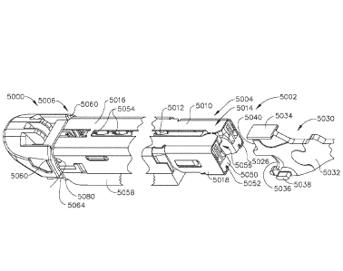
28b.
Annular channel 117 and rib 118 permit relative rotation between rotation
member 28
and housing 36. Elongated body 14 includes inner housing 122 and an outer
casing
124. Inner housing 122 is dimensioned to be received within outer casing 124
and
includes an internal bore 126 which extends therethrough and is dimensioned to
slidably receive a first articulation link 123 and control rod 52. The
proximal end of
housing 122 and casing 124 each include a pair of diametrically opposed
openings 130
28
Date Recue/Date Received 2020-04-09
and 128, respectively, which are dimensioned to receive radial projections 132
formed
on the distal end of rotation member 28. Projections 132 and openings 128 and
130
fixedly secure rotation member 28 and elongated body 14 in relation to each
other, both
longitudinally and rotatably. Rotation of rotation knob 28 with respect to
handle
assembly 12 thus results in corresponding rotation of elongated body 14 with
respect to
handle assembly 12.
[0128] An articulation mechanism 120 is supported on rotatable member 28 and
includes articulation lever 30, a cam member 136, a translation member 138,
and the
first articulation link 123. Articulation lever 30 is pivotably mounted about
pivot member
140 which extends outwardly from rotation member 28 and is formed integrally
therewith. A projection 142 extends downwardly from articulation lever 30 for
engagement with cam member 136. The distal end of translation member 138
includes
arm 160 which includes an opening 162 configured to receive a finger 164
extending
from the proximal end of articulation link 123. A pin 166 having a housing 168
constructed from a non-abrasive material, e.g., Teflon, is secured to
translation member
138 and dimensioned to be received within a stepped camming surface. In an
assembled condition, proximal and distal stepped portions 150 and 152 of cam
member
136 are positioned beneath flanges, such as flange 170, formed on rotation
member 28
to restrict cam member 136 to transverse movement with respect to the
longitudinal axis
of stapling apparatus 10. When articulation lever 30 is pivoted about pivot
member 140,
cam member 136 is moved transversely on rotation member 28 to move stepped
camming surface 148 transversely relative to pin 166, forcing pin 166 to move
proximally or distally along stepped cam surface 148. Since pin 166 is fixedly
attached
29
Date Recue/Date Received 2020-04-09
to translation member 138, translation member 138 is moved proximally or
distally to
effect corresponding proximal or distal movement of first actuation link 123.
[0129] A disposable loading unit sensing mechanism extends within the stapling
instrument from elongated body 14 into handle assembly 12. The sensing
mechanism
includes a sensor tube 176 which is slidably supported within bore 26 of
elongated body
14. The distal end of sensor tube 176 is positioned towards the distal end of
elongated
body 14 and the proximal end of sensor tube 176 is secured within the distal
end of a
sensor cylinder 178 via a pair of nubs 180. The distal end of a sensor link
182 is
secured to the proximal end of sensor cylinder 178. Sensor link 182 has a
bulbous end
184 which engages a camming surface on pivotable locking member 83. When a
disposable loading unit is inserted in the distal end of elongated body 14,
the disposable
loading unit engages the distal end of sensor tube 176 to drive sensor tube
176
proximally, and thereby drive sensor cylinder 178 and sensor link 182
proximally.
Movement of sensor link 182 proximally causes bulbous end 184 of sensor link
182 to
move distally of the camming surface to allow locking member 83 to pivot under
the bias
of spring 92 from a position permitting firing of stapling apparatus 10 to a
blocking
position, wherein blocking member 83 is positioned to engage actuation shaft
46 and
prevent firing of stapling apparatus 10. Sensor link 182 and locking member 83
function
to prevent firing of surgical stapling apparatus 10 after a disposable loading
unit has
been secured to elongated body 14, without first operating firing lockout
assembly 80.
[0130] Further to the above, cam member 136 can include a recess defined in
the
bottom portion thereof. A locking ring 184 having a nub portion 186 configured
to be
received within this recess can be positioned about sensor cylinder 178
between a
Date Recue/Date Received 2020-04-09
control tab portion 188 and a proximal flange portion 190. A spring 192
positioned
between flange portion 190 and locking ring 184 urges locking ring distally
about sensor
cylinder 178. When an articulating disposable loading unit having an extended
insertion
tip 193 (FIG. 16) is inserted into the distal end of elongated body 14 of
stapling
apparatus 10, insertion tip 193 causes tab portion 188 to move proximally into
engagement with locking ring 184 to urge locking ring 184 and nub 186
proximally of
recess 154 in cam member 136. With nub 186 positioned proximally of the recess
in
cam member 136, the cam member 136 is free to move transversely to effect
articulation of stapling apparatus 10. A non-articulating disposable loading
unit may not
have an extended insertion tip. As such, when a non-articulating disposable
loading unit
is inserted in elongated body 14, sensor cylinder 178 is not retracted
proximally a
sufficient distance to move nub 186 from recess 154. Thus, cam member 136 is
prevented from moving transversely by nub 186 of locking ring 184 which is
positioned
in the recess defined in the cam member 136 and articulation lever 30 is
locked in its
central position.
[0131] Referring to FIGS. 15-18, a disposable loading unit, such as disposable
loading unit 16a and/or 16b, for example, includes a proximal housing portion
200
adapted to releasably engage the distal end of body portion 14. A mounting
assembly
202 is pivotally secured to the distal end of housing portion 200, and is
configured to
receive the proximal end of tool assembly 17 such that pivotal movement of
mounting
assembly 202 about an axis perpendicular to the longitudinal axis of housing
portion
200 effects articulation of tool assembly 17 about pivot pin 244. Housing
portion 200 of
disposable loading unit 16 can include, one, engagement nubs 254 for
releasably
31
Date Recue/Date Received 2020-04-09
engaging elongated shaft 14 and, two, an insertion tip 193. Nubs 254 form a
bayonet
type coupling with the distal end of shaft 14. A second articulation link is
dimensioned to
be slidably positioned within a slot 258 formed between housing halves of
housing
portion 200.
[0132] Referring to FIGS. 19-27, tool assembly 17 includes anvil assembly 20
and
cartridge assembly 18. Anvil assembly 20 includes anvil portion 204 having a
plurality of
staple deforming concavities 206 and a cover plate 208 secured to a top
surface of anvil
portion 204 to define a cavity 210 therebetween. Cover plate 208 is provided
to prevent
pinching of tissue during clamping and firing of the surgical stapling
apparatus. Cavity
210 is dimensioned to receive a distal end of an axial drive assembly 212. A
longitudinal
slot 214 extends through anvil portion 204 to facilitate passage of retention
flange 284
of axial drive assembly 212 into the anvil cavity 210. A camming surface 209
formed on
anvil portion 204 is positioned to engage axial drive assembly 212 to
facilitate clamping
of tissue 198. A pair of pivot members 211 formed on anvil portion 204 are
positioned
within slots 213 formed in carrier 216 to guide the anvil portion between the
open and
clamped positions. A pair of stabilizing members can engage a respective
shoulder 217
formed on carrier 216 to prevent anvil portion 204 from sliding axially
relative to staple
cartridge 220 as camming surface 209 is deformed.
[0133] Cartridge assembly 18 includes a carrier 216 which defines an elongated
support channel 218. Elongated support channel 218 is dimensioned and
configured to
receive a staple cartridge 220. Corresponding tabs 222 and slots 224 formed
along
staple cartridge 220 and elongated support channel 218 function to retain
staple
cartridge 220 within support channel 218. A pair of support struts 223 formed
on staple
32
Date Recue/Date Received 2020-04-09
cartridge 220 are positioned to rest on side walls of carrier 216 to further
stabilize staple
cartridge 220 within support channel 218. Staple cartridge 220 includes
retention slots
225 for receiving a plurality of fasteners 226 and pushers 228. A plurality of
spaced
apart longitudinal slots 230 extend through staple cartridge 220 to
accommodate
upstanding cam wedges 232 of actuation sled 234. A central longitudinal slot
282
extends along the length of staple cartridge 220 to facilitate passage of a
knife blade
280. During operation of the surgical stapler, actuation sled 234 translates
through
longitudinal slots 230 of staple cartridge 220 to advance cam wedges 232 into
sequential contact with pushers 228, to cause pushers 228 to translate
vertically within
slots 225 and urge fasteners 226 from slots 225 into the staple deforming
cavities 206
of anvil assembly 20.
[0134] Further to the above, the shaft of the surgical stapling instrument can
include
upper and lower mounting portions 236 and 238. Each mounting portion includes
a
threaded bore 240 on each side thereof dimensioned to receive threaded bolts
242 for
securing the proximal end of carrier 216 thereto. A pair of centrally located
pivot
members 244 extends between upper and lower mounting portions via a pair of
coupling members which engage the distal end of housing portion 200. Housing
portion
200 of the disposable loading unit can include upper and lower housing halves
contained within an outer casing 251. A second articulation link 256 is
dimensioned to
be slidably positioned within a slot formed between the housing halves. A pair
of blow
out plates 254 are positioned adjacent the distal end of housing portion 200
adjacent
the distal end of axial drive assembly 212 to prevent outward bulging of drive
assembly
212 during articulation of tool assembly 17. The second articulation link 256
includes at
33
Date Recue/Date Received 2020-04-09
least one elongated metallic plate. Preferably, two or more metallic plates
are stacked to
form link 256. The proximal end of articulation link 256 includes a hook
portion 258
configured to engage first articulation link 123 and the distal end includes a
loop 260
dimensioned to engage a projection 262 formed on mounting assembly 202.
Projection
262 is laterally offset from pivot pin 244 such that linear movement of second
articulation link 256 causes mounting assembly 202 to pivot about pivot pins
244 to
articulate tool assembly 17.
[0135] The distal end of drive beam 266 is defined by a vertical support strut
278
which supports a knife blade 280, and an abutment surface 283 which engages
the
central portion of actuation sled 234 during a stapling procedure. Surface 285
at the
base of surface 283 is configured to receive a support member 287 slidably
positioned
along the bottom of the staple cartridge 220. Knife blade 280 is positioned to
translate
slightly behind actuation sled 234 through a central longitudinal slot 282 in
staple
cartridge 220 to form an incision between rows of stapled body tissue. A
retention
flange projects distally from the vertical strut and supports a cylindrical
cam roller 286 at
its distal end. Cam roller 286 is dimensioned and configured to engage cam
surface 209
on anvil body 204 to clamp anvil portion 204 against body tissue.
[0136] In various embodiments, referring now to FIGS. 30 and 31, an end
effector of a
surgical stapling instrument can comprise a first jaw 680 including a staple
cartridge
assembly and a second jaw 670. The first jaw 680 can include a pan 680a, a
cartridge
body 682 positionable in the pan 680a, and a sled 690 which is movable through
the
cartridge body 682 to lift drivers 692 toward deck 682a of cartridge body 682
and eject
the staples 684 removably stored in staple cavities defined therein. The
cartridge body
34
Date Recue/Date Received 2020-04-09
682 can further comprise a plurality of slots 682b which can each be
configured to
receive a cam of the sled 690, such as cams 690a-690c, for example, which can
be
configured to engage and lift the drivers 692. The staple cartridge assembly
can further
comprise a layer B2 which can be attached to the cartridge body 682 utilizing
connectors S3 and S4. In various embodiments, each connector S3 and S4 can
comprise a suture which ties the layer B2 to the cartridge body 682. For
instance, the
connector S3 can mount the distal end of the layer B2 to the distal end 682f
of the
cartridge body 682 while the connector S4 can mount the proximal end of the
layer B2
to the proximal end 682e of the cartridge body 682. In use, a cutting member,
such as
cutting member 660, for example, can be advanced through the cartridge body
682 and
incise, or otherwise deactivate, the connectors S3 and S4. For instance, the
cutting
member 660 can comprise a body 662, flanges 664a and 664b which are configured
to
engage the second jaw 670 and the first jaw 680, respectively, and a cutting
member 66
which is configured to traverse a longitudinal slot 682c defined in the
cartridge body
682a. The cutting member 660 can be advanced distally through the cartridge
body
682 by a firing member assembly 650. The firing member assembly 650 can
comprise
a shaft 652 comprised of a plurality of layers including a distal end 654
engaged within
the cutting member body 662 and a proximal end 656 configured to receive a
firing
force applied thereto.
[0137] When the firing force is applied to the firing member 650, further to
the above,
the flange 664a can engage the second jaw 670 and pivot the second jaw 670
downwardly toward the first jaw 680. The second jaw 670 can comprise an anvil
assembly 623 which can include a frame 672 and an anvil plate including a
plurality of
Date Recue/Date Received 2020-04-09
anvil pockets defined therein. As the firing member 650 is being advanced
distally, the
cutting member 660 can pass through a longitudinal slot 670b defined in the
anvil plate.
Similar to the above, the second jaw 670 can further comprise a layer B1
attached
thereto by one or more connectors, such as connectors Si and S2, for example.
Also
similar to the above, the connectors Si and S2 can each comprise a suture,
wherein
the connector Si can be configured to releasably hold the distal end of the
layer B1 to
the distal end 670e of the anvil assembly 623 and wherein the connector S2 can
be
configured to releasably hold the distal end of the layer B2 to the proximal
end 670c of
the anvil assembly 623. In various embodiments, the anvil assembly 623 can
comprise
a distal nose 676 assembled to the frame 672 and can include a slot 676a
defined
therein which is configured to receive the connector Si. Similarly, the
proximal end of
the frame 672 can include a slot 672a defined therein which is configured to
receive the
connector S2. In either event, in various embodiments, the connectors Si and
S2 can
extend around the entirety of the anvil frame 672 while, in other embodiments,
the
connectors Si and S2 can engage the sides of the anvil assembly 623. When the
cutting member 660 is advanced distally through the anvil assembly 623, the
cutting
member 660 can transect, or otherwise deactivate, the connectors Si and S2 to
release
the layer B1 from the anvil assembly 623. More particularly, in various
embodiments,
the layer B1 can be positioned on one side of the patient tissue and the layer
B2 can be
positioned on the opposite side of the patient tissue, wherein the staples 684
can then
be fired through the layer B2, the patient tissue, and the layer B1 when the
firing
member 650 is advanced distally. As the firing member 650 is advanced
distally, the
cutting member 660 can progressively transect the connectors S1-S4 as the
layers B1
36
Date Recue/Date Received 2020-04-09
and B2 are progressively transected by the cutting member 660. For instance,
the
cutting member 660 can transect connectors S2 and S4 at the beginning of the
stroke
and connectors Si and S3 at the end of the stroke. In various embodiments,
referring
now to FIGS. 32 and 33, an end effector 716 can comprise a first jaw 718 and a
second
jaw 720 wherein a connector 774 can be embedded within a slot 770e defined in
an
anvil 772 of the second jaw 720.
[0138] Referring to FIG. 33A, an end effector of a surgical stapling
instrument can
comprise a first jaw and a second jaw, wherein at least one of the first jaw
and the
second jaw can be configured to be moved relative to the other. The end
effector can
comprise a first jaw including a staple cartridge channel 1050 and a second
jaw
including an anvil, wherein the anvil can be pivoted toward and/or away from
the staple
cartridge channel 1050, for example. In various alternative embodiments, the
first jaw
including a staple cartridge thereto can be pivoted toward and/or away from
the second
jaw including the anvil. In either event, the staple cartridge channel 1050
can be
configured to receive a staple cartridge 1060, for example, which can be
removably
retained within the staple cartridge channel 1050. The staple cartridge 1060
can
comprise a cartridge body 1062, a cartridge deck 1064, and a tissue thickness
compensator 1000 wherein, as illustrated in FIG. 33A, tissue thickness
compensator
1000 may be removably positioned against or adjacent cartridge deck 1064.
Similar to
other embodiments described herein, referring now to FIGS. 33A and 34, the
cartridge
body 1062 can comprise a plurality of staple cavities 1066 and a staple 1002
positioned
within each staple cavity 1066. Also similar to other embodiments described
herein, the
staples 1002 can be supported by staple drivers positioned within the
cartridge body
37
Date Recue/Date Received 2020-04-09
1062 wherein a sled and/or firing member, for example, can be advanced through
the
staple cartridge 1060 to lift the staple drivers upwardly within the staple
cavities 1066
and eject the staples 1002 from the staple cavities 1066.
[0139] Referring to FIG. 34, tissue thickness compensators, such as tissue
thickness
cornpensators 1000 and 1000', can be fastened to tissue T in order, for
example, to
provide support for fastened tissue T. As illustrated in FIG. 34, tissue
thickness
cornpensators 1000 and 1000' can be fastened to opposite sides of tissue T. A
tissue
thickness compensator such as, for example, tissue thickness compensator 1000,
may
cornprise an inner portion 1004 and an outer portion 1006 which may form an
outer
perimeter at least partially surrounding the inner portion 1004. The outer
portion 1006
may be more flexible than the inner portion 1004. In various circumstances,
the outer
portion 1006 may comprise sufficient flexibility to provide an atraumatic
tissue
contacting surface for tissue T, and the inner portion may comprise sufficient
rigidity to
provide adequate support for fastened tissue T.
[0140] Referring again to FIG. 34, the outer portion 1006 of tissue thickness
compensator 1000 may include an outer edge 1008. To improve its flexibility,
the outer
portion 1006 may include multiple slits 1010. In addition, pieces of the outer
edge 1008
and the outer portion 1006 can be cut or removed to improve the flexibility of
the outer
portion 1006. As illustrated in FIG. 34, slits 1010 can begin at the outer
edge 1008 and
can follow various paths terminating within the outer portion 1006. For
example, a slit,
such as slit 1010A, may begin at the outer edge 1008 then follow a path
substantially
perpendicular to the outer edge 1008 terminating within the outer portion
1006. In
another example, a slit, such as slit 1010B, may also begin at the outer edge
1008 then
38
Date Recue/Date Received 2020-04-09
follow a path at an acute angle with the outer edge 1008, also terminating
within the
outer portion 1006. Tissue thickness compensator 1000 can be manufactured with
slits
1010 in the outer portion 1006. Alternatively, tissue thickness compensator
1000 can be
manufactured without the slits 1010, which can be incorporated into the outer
portion
1006 prior to the implantation thereof, for example.
[0141] As described above, and as illustrated in FIG. 34, staples 1002 can be
configured to at least partially capture tissue thickness compensator 1000
when the
staples 1002 are moved from their unfired positions to their fired positions.
Furthermore,
staples 1002 can be fired in rows and each row may include multiple staples
1002. A
row of staples 1002, for example row 1012, can be fastened onto the outer
portion 1006
of tissue thickness compensator 1000 such that slits 1010 may be positioned
between
the staples 1002 of row 1012 to allow for sufficient support for the staples
1002 while
maintaining an adequate flexibility within the outer portion 1006.
Alternatively, under
certain circumstances, slits 1010 can be positioned within the staples 1002,
for
example, to provide flexibility within the staples 1002.
[0142] Referring now to FIG. 35, tissue thickness compensator 1000 may include
a
plurality of openings 1014 extending therethrough. As illustrated in FIG. 35,
the
openings 1014 may comprise generally cylindrical shapes. Alternatively,
openings 1014
may comprise cone shapes which can be narrow on one side and wide on the other
side of tissue thickness compensator 1000. Other geometrical shapes for
openings
1014 are contemplated within the scope of this disclosure. Tissue thickness
compensator 1000 may also include multiple cavities 1016. As illustrated in
FIG. 35,
cavities 1016 may comprise generally cylindrical shapes, sometimes with
tapered outer
39
Date Recue/Date Received 2020-04-09
portions. Other geometrical shapes for cavities 1016 are contemplated within
the scope
of this disclosure. For example cavities 1016 can include closed ended cones.
Openings 1014 and/or cavities 1016 may provide regions of localized
flexibility within
tissue thickness compensator 1000 and can be positioned within the outer
portion 1006,
the inner portion 1004 and/or both portions 1004 and 1006 to enhance the
flexibility of
the tissue thickness compensator 1000. Furthermore, as illustrated in FIG. 35,
tissue
thickness compensator 1000 can include combinations of slits 1010, openings
1014,
and/or cavities 1016 to yield a desired degree of flexibility.
[0143] Referring now to FIGS. 36-39, to improve its flexibility, the thickness
of the
tissue thickness compensator 1000 can include patterns that may provide
regions of
localized flexibility. Such patterns can be embossed patterns which can be
molded or
carved into the tissue thickness compensator 1000. As illustrated in FIG. 36,
tissue
thickness compensator 1000 can include a pattern 1020 comprising a plurality
of
pyramids 1018 which can be arranged, for example, in rows. Pyramids 1018, as
illustrated in FIG. 37, can be separated from each by a distance "D." The
degree of
flexibility of tissue thickness compensator 1000 can, in part, be controlled
by increasing
or decreasing distance "D" between pyramids 1018. Pyramids 1018 can be
arranged in
other pattern arrangements which are contemplated within the scope of the
present
disclosure. In addition, other geometrical shapes, cones for example, and
combinations
thereof can also be used and are contemplated within the scope of the present
disclosure. As illustrated in FIG. 38, tissue thickness compensator 1000 may
comprise a
corrugated pattern 1022. FIG. 38 shows a cross sectional view of corrugated
pattern
1022 of tissue thickness compensator 1000 which may include multiple peaks
1024 and
Date Recue/Date Received 2020-04-09
multiple valleys 1026. The various patterns illustrated herein and
combinations thereof
can be positioned within the outer portion 1006 and/or the inner portion 1004
to
enhance the flexibility of the tissue thickness compensator 1000.
[0144] Further to the above, referring to FIGS. 40 and 41, the outer edge 1008
of
tissue thickness compensator 1000 can comprise a generally atraumatic profile
which
can minimize an impact upon tissue T, for example, during and/or after the
capturing of
the tissue T and the tissue thickness compensator 1000 by staples 1002. For
example,
as illustrated in FIGS. 40 and 41, outer edge 1008 can comprise a generally
scalloped
profile. Other atraumatic profiles such as a feathered profile, for example,
for the outer
edge 1008 are also contemplated within the scope of the current disclosure. In
addition,
tissue thickness compensator 1000 may also comprise an atraumatic nose portion
1028
and/or an atraumatic tail portion 1030. As illustrated in FIGS. 40 and 41,
atraumatic
nose portion 1028 can comprise, for example, a generally curved shape and
atraumatic
tail portion 1030 may, for example, comprise a split tail with flexible ends
1032. Other
atraumatic shapes for the nose portion 1028 and/or the tail portion 1030 are
also
contemplated within the scope of the current disclosure.
[0145] Referring again to FIGS. 40 and 41, tissue thickness compensator 1000
can
comprise a gripping member 1034, which can reduce slippage between the tissue
thickness compensator 1000 and the cartridge deck 1064 when the tissue
thickness
compensator 1000 is placed against the cartridge deck 1064. As illustrated in
FIG. 40,
gripping member 1034 can comprise multiple cylindrically shaped protrusions
1036, for
example, which can be joined with corresponding recesses in the cartridge deck
1064.
Gripping member 1034, as illustrated in FIG. 41, can comprise an arrow head
shaped
41
Date Recue/Date Received 2020-04-09
protrusion 1038 which can be matted with a corresponding recess in the
cartridge deck
1064. Other gripping means for gripping tissue thickness compensator 1000 to
cartridge
deck 1064 are contemplated within the scope of the present disclosure.
Gripping
member 1034, as illustrated in FIGS. 40 and 41, can be positioned in the nose
portion
1028. Alternatively, gripping member 1034 can be positioned in other portions
of tissue
thickness compensator 1000 such as, for example, tail portion 1030.
[0146] Referring now to FIGS. 42-44, outer portion 1006 of tissue thickness
compensator 1000 can comprise a cushioning member 1043 which can provide a
pliable edge that contacts tissue T, for example, during and/or after the
capturing of the
tissue T and the tissue thickness compensator 1000 by staples 1002. In at
least one
embodiment, as illustrated in FIG. 44, cushioning member 1043 may comprise
sufficient
structural elasticity to collapse and/or bend when compressed against the
tissue T. As
illustrated in FIG. 43, cushioning member 1043 can partially extend over the
outer edge
1008 and may be attached to outer edge 1008 by an adhesive, for example. Other
attachment means for attaching cushioning member 1043 to outer edge 1008 are
contemplated within the scope of the current disclosure. Alternatively,
cushioning
member 1043 can be an integral part of tissue thickness compensator 1000 that
may be
manufactured therewith. Cushioning member 1043 may comprise a biocompatible
foam
which can be comprised of a biodegradable material such as, for example, PGA,
PCL,
PLLA, and/or combinations thereof, for example. Furthermore, cushioning member
1043 may be comprised, at least in part, of alginate and/or oxidized
regenerated
cellulose (ORC). For example, cushioning member 1043 may include a plurality
of
42
Date Recue/Date Received 2020-04-09
alginate and/or ORC beads which may soften upon implantation in a patient
which may
increase the softness of cushioning member 1043.
[0147] The outer edge 1008 of the compensator 1000 may comprise a thickness
greater than the thickness of the outer portion 1006. The greater thickness of
the outer
edge 1008 may provide an atraumatic surface that contacts tissue T. Referring
to
FIGS. 45 and 46, outer portion 1006 of tissue thickness compensator 1000 can
comprise a rolled outer edge 1046 which can be at least partially extended
around outer
portion 1006 and inwardly rolled towards the inner portion 1004. Similar to
the above,
rolled outer edge 1046 can provide a pliable outer edge that contacts tissue
T, for
example, during and/or after the capturing of the tissue T and the tissue
thickness
compensator 1000 by staples 1002.
[0148] Referring to FIGS. 47-49, as described above, the staple cartridge
channel
1050 can be configured to receive a staple cartridge 1060 which can comprise a
cartridge body 1062, a cartridge deck 1064. In addition, a tissue thickness
compensator
such as, for example, tissue thickness compensator 1100 may be removably
positioned
against or adjacent cartridge deck 1064, as illustrated in FIG. 47.
[0149] Referring again to FIGS. 47-49, a tissue thickness compensator may be
configured to be absorbed after implantation in a patient. The absorption
process may
initially reduce the tissue thickness compensator into smaller pieces which
may include
rough edges that may have undesirable effects on surrounding tissue T. To
mitigate
these effects, tissue thickness compensator 1100 may be at least partially
assembled
from a plurality of pieces 1140, which each may have atraumatic outer
peripheries and
may be joined together to form a single structure, as illustrated in FIG. 48.
Pieces 1140
43
Date Recue/Date Received 2020-04-09
can be joined to form tissue thickness compensator 1100 in a manner such that
the
absorption process may first reduce tissue thickness compensator 1100 into
pieces
1140 thereby minimizing the presence of rough edges. For example, pieces 1140
may
comprise circular profiles and may be joined together by thermal bonding to
form tissue
thickness compensator 1100. Other profiles and other means for joining pieces
1140
are contemplated within the scope of the present disclosure. In one example,
pieces
1140 can be joined together by an adhesive 1143 (See FIG. 48) configured to be
absorbed faster than pieces 1140 to allow separation of the pieces 1140 in an
initial
stage of the absorption process. As illustrated in FIG. 48, pieces 1140 can be
arranged
in an overlapping array wherein an end portion of one of the pieces 1140 may
overlap
with an end portion of another one of the pieces 1140 such that the two end
portions of
the pieces 1140 are releasably attached to each other, for example, by an
adhesive.
Under certain circumstances, pieces 1140 can be arranged in another
overlapping array
wherein one of the pieces 1140 can be positioned over and releasably attached
to a
plurality of pieces 1140, as illustrated in FIG. 49.
[0150] Referring to FIGS. 50-53, as described above, a tissue thickness
compensator
may be configured to be absorbed after implantation in a patient and the
absorption
process may initially reduce the tissue thickness compensator into random
smaller
pieces. Guiding the absorption process to yield small pieces with atraumatic
outer
edges can be achieved, as described above, by starting with small pieces
having
atraumatic outer edges. Another approach may include modifying the tissue
thickness
compensator in such a manner that allows its separation into smaller pieces
having
atraumatic peripheries in an initial stage of the absorption process. For
example, as
44
Date Recue/Date Received 2020-04-09
illustrated in FIG. 50, a tissue thickness compensator 1200 may comprise a
pattern
such as pattern 1212, for example, which can be molded or carved into the
tissue
thickness compensator 1200 to yield, for example, a plurality of circular
shaped portions
1210. The portions 1210 may be defined by reducing the thickness of tissue
thickness
compensator 1200 along circumferences 1214 of the circular shaped portions
1210, as
illustrated in the cross-sectional view in FIG. 51. In result, a faster
absorption along the
circumferences 1214 of circular shaped portions 1210 may occur which may lead
to a
separation of the circular shaped portions 1210 from each other in an initial
stage of the
absorption process. Patterns comprising portions with other geometrical shapes
with
atraumatic outer peripheries are contemplated within the scope of the current
disclosure. For example, as illustrated in FIG. 52, tissue thickness
compensator 1200'
may comprise a pattern 1216 comprising portions 1218 which may include
profiles that
extend longitudinally in a wave-like profile along a length of tissue
thickness
compensator 1200'. In another example, as illustrated in FIG. 53, tissue
thickness
compensator 1200" may comprise a pattern 1220 which may include hexagonal
shaped
portions 1222.
[0151] Referring to FIG. 54, as described above, a tissue thickness
compensator,
such as tissue thickness compensator 1250, may be captured along with tissue T
by
staples, such as staples 1002, for example, and may be configured to be
reduced into
atraumatic pieces, such as pieces 1226, for example, in an initial stage of
the
absorption process after implantation in a patient. Upon separation, pieces
1226 can
move and/or slide relative to each other which may impact surrounding tissue
T. To
minimize relative motion between pieces 1226, fired staples 1002 can be
spatially
Date Recue/Date Received 2020-04-09
arranged onto tissue thickness compensator 1250 such that a staple 1002 may
capture
multiple pieces 1226, as illustrated in FIG. 54. This may also aid in
maintaining tissue
thickness compensator 1250 in a substantially singular structure even after
pieces 1226
are separated from each other in the initial stage of the absorption process.
As such,
the tissue thickness compensator 1250 may continue to provide support for
tissue T
captured by staples 1002 after pieces 1226 are separated from each other in
the initial
stage of the absorption process.
[0152] Further to the above, referring now to FIG. 55, yet another approach
can be
taken to guide the absorption process of a tissue thickness compensator to
yield small
pieces with atraumatic outer edges. For example, as illustrated in FIG. 55, a
tissue
thickness compensator such as tissue thickness compensator 1300 may comprise a
plurality of slits 1310 which can be strategically positioned to improve the
flexibility of
tissue thickness compensator 1300, as described above. In addition, slits 1310
may
partially divide tissue thickness compensator 1300 into a plurality of
portions 1312 which
may separate from each other during an initial stage of the absorption
process. Slits
1312 can reduce the width of tissue thickness compensator 1300 along outer
peripheries 1314 of portions 1312, as illustrated in FIG. 55. This reduction
in width may
lead to faster absorption along the outer peripheries 1314 of portions 1312,
which can
result in reducing tissue thickness compensator 1300 into separate portions
1312 during
the initial stage of the absorption process.
[0153] Referring generally to FIGS. 55A-57, as described above, the staple
cartridge
channel 1050 can be configured to receive a staple cartridge 1060, for
example, which
in at least one embodiment, can be removably retained within the staple
cartridge
46
Date Recue/Date Received 2020-04-09
channel 1050. In various embodiments, the staple cartridge 1060 can comprise a
cartridge body 1062, a cartridge deck 1064, and a tissue thickness compensator
1400
wherein, in at least one embodiment, as illustrated in FIG. 55A, tissue
thickness
compensator 1400 may be removably positioned against or adjacent cartridge
deck
1064 and may comprise protrusions (not shown), as described above for mating
engagement with recesses 1402.
[0154] Referring again to FIGS. 55A-57, compensator 1400 may comprise a
plurality
of layers. For instance, compensator 1400 may comprise a first layer 1400A,
and a
second layer 1400B, which can be positioned over the first layer 1400A. In
addition, an
outer periphery 1418 of the second layer 1400B may be at least partially
extended
beyond an outer periphery 1420 of the first layer 1400A. Furthermore, the
first layer
1400A and the second layer 1400B may comprise different degrees of stiffness.
For
example, the second layer 1400B may be configured to be more flexible than the
first
layer 1400A. As illustrated in FIG. 55B, this arrangement may provide tissue
thickness
compensator 1400 with a sufficiently rigid inner region, comprised from the
first layer
1400A and the second layer 1400 B, which may be suitable to provide adequate
support for staples 1002, and a sufficiently flexible outer region, comprised
from the
second layer 1400B, which may be suitable to provide sufficient flexibility to
soften the
impact upon tissue T, for example, during and/or after the capturing of the
tissue T and
the tissue thickness compensator 1400 by staples 1002. Layers 1400A and 1400B
can
be joined together, for example, by an adhesive. Other attachment means for
attaching
the first layer 1400A to the second layer 1400B are contemplated within the
scope of
the current disclosure.
47
Date Recue/Date Received 2020-04-09
[0155] Further to the above, referring again to FIG. 55A, the first layer
1400A may
include an inner portion 1404 and an outer portion 1406 at least partially
surrounding
the inner portion 1404, wherein the outer portion 1406 may be configured to be
more
flexible than the inner portion 1404. For example, as illustrated in FIG. 55A,
the outer
portion 1404 may comprise a plurality of slits 1410, which as described above,
may
increase the flexibility of the outer portion 1404. Furthermore, as described
above, the
second layer 1400B may be configured to be more flexible than the first layer
1400A.
This arrangement may provide tissue thickness compensator 1400 with three
regions of
different rigidity including a first inner region having the most rigidity,
the inner region
being comprised of inner portion 1404 of first layer 1400A and second layer
1400B, a
middle region having an intermediate rigidity, the middle region being
comprised of
outer portion 1408 of first layer 1400A and the second layer 1400B, and a
third outer
region having the least rigidity, the third region being comprised solely of
the second
layer 1400B.
[0156] Referring now to FIGS. 56 and 57, the second layer 1400B of tissue
thickness
compensator 1400 can comprise a woven structure 1440, which may include a
plurality
of fibers 1442 which may be woven into woven structure 1440. The woven
structure
1440 may provide the second layer 1400B with sufficient flexibility to soften
the impact
upon tissue T, for example, during and/or after the capturing of the tissue T
and the
tissue thickness compensator 1400 by staples 1002. Furthermore, the outer
periphery
1418 can be comprised of fibers 1042 which can provide an atraumatic tissue
contacting surface to minimize impact upon tissue T, as described above. Woven
structure 1440 and fibers 1042 can be comprised of biocompatible materials.
48
Date Recue/Date Received 2020-04-09
Furthermore, woven structure 1040 and/or fibers 1042 can be comprised from a
bioabsorbable material such as PLLA, PGA, PCL, and/or combinations thereof,
for
example.
[0157] Referring now to FIGS. 60-60B, as described in greater detail below, a
tissue
thickness compensator 11050 can comprise a proximal end 11053 and a distal end
11055 wherein the proximal end 11053 and/or the distal end 11055 can comprise
one
or more strain relief portions which can reduce the rigidity of the tissue
thickness
compensator 11050 and the rigidity of the tissue being stapled. The distal end
11055
of the tissue thickness compensator 11050 can comprise one or more slots 11058
defined therein. The slots 11058 can comprise cuts and/or notches, for
example,
defined in the tissue thickness compensator 11050. The slots 11058 can define
projections, or tabs, 11056 which can be configured to at least partially move
and/or flex
relative to one another and/or the body portion of the tissue thickness
compensator
11050. Stated another way, the slots 11058 can provide localized strain relief
to the
tissue thickness compensator 11050 and the underlying tissue. In certain
circumstances, the tabs 11056 of a first tissue thickness compensator 11050
can be
overlapped with a proximal end 11053 of a second tissue thickness compensator
11050. In various circumstances, the slots 11058 can permit the first tissue
thickness
compensator 11050 and the second tissue thickness compensator to pivot
relative to
one another. In certain circumstances, referring primarily to FIG. 60B, the
tabs 11056 of
a first tissue thickness compensator 11050 can be overlapped with the tabs
11056 of a
second tissue thickness compensator 11050. In various circumstances, the slots
11058
in the overlapped distal ends 11055 can further reduce the rigidity within the
underlying
49
Date Recue/Date Received 2020-04-09
tissue. Although the illustrated embodiment of tissue thickness compensator
11050
only comprises an arrangement of tabs 11057 and slots 11058 on one end
thereof, a
tissue thickness compensator may comprise an arrangement of tabs 11056 and
slots
11058 on both ends thereof, for example.
[0158] In certain embodiments, further to the above, each tab 11056 can
comprise a
tapered profile. For instance, each tab 11056 can comprise a base attached to
the
body of the tissue thickness compensator 11050 having a base width and a free
end on
the opposite end thereof having an end width, wherein the base width can be
wider than
the end width. In certain embodiments, the end width can be wider than the
base width.
Referring primarily to FIG. 60B, an end 11055 can comprise a plurality of tabs
11056
having different configurations. For instance, the tabs 11056 can have
different lengths.
As illustrated in FIG. 60B, an end-most tab 11056a can have a first length, a
second tab
11056b can have a second length which is longer than the first length, a third
tab
11056c can have a third length which is longer than the second length, a
fourth tab
11056d can have a fourth length which is longer than the third length, a fifth
tab 11056e
can have a fifth length which is longer than the fourth length, and a sixth
tab 11056f can
have a sixth length which is longer than the fifth length, for example. In
such an
embodiment, the tabs 11056 can become progressively shorter toward the distal
end of
the tissue thickness compensator 11050. In other embodiments, the lengths of
the tabs
11056 can be arranged in any other suitable arrangement.
[0159] In various circumstances, further to the above, a layer can comprise
edges
which define the perimeter of the layer. These edges may be straight,
substantially
straight, linear, and/or substantially linear, in certain circumstances. In
some such
Date Recue/Date Received 2020-04-09
circumstances, the layer edges may impinge on and/or otherwise affect the
surrounding
tissue. Also, in some such circumstances, the edges may be rigid and may
rigidly
support the tissue. In effect, certain portions of the tissue may be
unsupported by the
layer which are adjacent to other portions of the tissue which are rigidly
supported by
the layer without transition therebetween. Referring to FIGS. 60-60B once
again, the
perimeter of the tissue thickness compensator 11050 can include a contoured
configuration which can provide a region of transitional rigidity to the
underlying tissue.
The perimeter of the tissue thickness compensator 11050 can comprise a
plurality of
notches or recesses 11059 defined therein which can define tabs 11057. Similar
to the
above, the tabs 11057 can extend from the body of the tissue thickness
compensator
11050 and can move relative thereto. Also similar to the above, each tab 11057
can
comprise a base end attached to the body of the tissue thickness compensator
11050
and free end which is movable relative to the base end. In certain
circumstances, the
free end of a tab 11057 can have a width which is narrower than the width of
the base
end of the tab 11057 while, in other circumstances, the free end of a tab
11057 can
have a width which is wider than the width of the base end of the tab 11057.
The tabs
11057 can comprise any suitable configuration such as a semi-circular, or an
at least
partially arcuate, configuration, for example. As a result of the above, the
tissue
underlying and/or fastened to the body portion of the tissue thickness
compensator
11050 can be rigidly supported by the body portion, the tissue underlying
and/or
fastened to the tabs 11057 can be less than rigidly supported by the tabs
11057, and
the tissue adjacent to the tabs 11057, but not underlying the tabs 11057, may
be
unsupported by the tissue thickness compensator 11050.
51
Date Recue/Date Received 2020-04-09
[0160]
Referring now to FIGS. 58 and 59, a staple cartridge assembly 11100 can
comprise a cartridge body 11110 and a tissue thickness compensator 11150
attached
to the cartridge body 11110. The cartridge assembly 11100 can further comprise
one or
more attachment members 11160 configured to releasably hold the tissue
thickness
compensator 11150 to the cartridge body 11110. In at least one circumstance,
each
attachment member can comprise a strap which extends around the cartridge body
11110 and the tissue thickness compensator 11150. In use, further to the
above, a
firing member 10030 can be advanced through the staple cartridge 11100 to
incise the
tissue thickness compensator 11150, fire the staples at least partially stored
in the
cartridge body 11110, and sever the attachment members 11160. The tissue
thickness
compensator 11150 can comprise a first, or proximal, end 11157 and a second,
or
distal, end 11155. The distal end 11155 can comprise an elongate projection
11156
extending from a body portion 11153 of the tissue thickness compensator 11150.
As
illustrated in FIG. 58, the elongate projection 11156 can extend distally with
respect to
the distal-most attachment member 11160. In at least the illustrated
embodiment, the
cartridge body 11110 can comprise a deck 11113 within which staple cavities of
the
cartridge body 11110 can be defined. In various circumstances, the body 11153
of the
tissue thickness compensator 11150 can be configured and arranged such that it
covers
the deck 11113 and the staple cavities defined in the cartridge body 11110. In
at least
some circumstances, as also illustrated in FIG. 58, the elongate projection
11156 can
extend distally from the deck 11113 and extend distally with respect to the
staple
cavities defined in the deck 11113.
52
Date Recue/Date Received 2020-04-09
[0161] In use, further to the above, the tissue thickness compensator 11150
can be
fastened to tissue and can provide tissue thickness compensation properties,
as
described herein. Similar to the above, the tissue underlying the tissue
thickness
compensator 11150 may be rigidly supported by the tissue thickness compensator
11150 and the staples securing the same whereas the tissue surrounding the
tissue
thickness compensator 11150 may be unsupported by the tissue thickness
compensator 11150 and may be flexible. In such circumstances, the tissue
between
the flexible unsupported tissue and the rigidly supported tissue underlying
the tissue
thickness compensator 11150, i.e., the transition tissue, can undergo an
undesirable
amount of strain. Such strain may negatively impact the transition tissue. For
instance,
when a tissue thickness compensator is secured to pulmonary, or lung, tissue,
for
example, the tissue immediately surrounding the perimeter of the tissue
thickness
compensator, i.e., the perimeter tissue, may tear in certain circumstances,
especially
the perimeter tissue adjacent to and/or surrounding the distal end of the
tissue thickness
compensator, i.e., the end perimeter tissue. The distal projection 11156 of
the tissue
thickness compensator 11150, however, can support the end perimeter tissue.
Stated
another way, the distal projection 11156 can provide transitional support to
the end
perimeter tissue. Such transitional support can be less than the support
provided by the
body of the tissue thickness compensator 11150 and can mitigate the change in
strain
between the unsupported tissue and the fully supported tissue underlying the
tissue
thickness compensator 11150. In various circumstances, the distal projection
11156
can provide an enlarged area in which force can be transmitted between the
unstapled
tissue and the stapled tissue. The distal projection 11156 can be configured
to flex and
53
Date Recue/Date Received 2020-04-09
move with the unsupported tissue and the tissue thickness compensator 11150.
In
various circumstances, the distal projection 11156 can move relative to the
body portion
of the tissue thickness compensator 11150 and/or the unsupported tissue.
[0162] The tissue thickness compensator 11150, referring again to FIGS. 58 and
59,
can further comprise a notch 11157 defined in the proximal end 11153 thereof.
The
notch 11157 can be defined between two distally extending projections 11158.
The
notch 11157 can comprise any suitable shape, such as a parabolic shape, for
example.
Similar to the above, the distally extending projections 11158 can provide
transitional
support to the proximal end perimeter tissue. Such transitional support can be
less than
the support provided by the body of the tissue thickness compensator 11150 and
can
mitigate the change in strain between the unsupported tissue and the fully
supported
tissue underlying the tissue thickness compensator 11150. In various
circumstances,
the proximal projections 11158 can provide an enlarged area in which force can
be
transmitted between the unstapled tissue and the stapled tissue. The proximal
projections 11158 can be configured to flex and move with the unsupported
tissue and
the tissue thickness compensator 11150. In various circumstances, the proximal
projections 11158 can move relative to the body portion of the tissue
thickness
compensator 11150, each other, and/or the unsupported tissue. Various
alternative
embodiments are envisioned in which more than two projections extend from the
proximal end and/or distal end of a tissue thickness compensator.
[0163] As illustrated in FIG. 59, two or more tissue thickness compensators
11150
can be implanted in an end-to-end manner along a path. In such circumstances,
the
distal end 11155 of a first tissue thickness compensator 11150 can overlap
with the
54
Date Recue/Date Received 2020-04-09
proximal end 11153 of a second tissue thickness compensator 11150. Similarly
the
distal end 11155 of the second tissue thickness compensator 11150 can overlap
with
the proximal end 11153 of a third tissue thickness compensator 11150. In
various
circumstances, the distal projection 11156 of the first tissue thickness
compensator
11150 can be aligned, or at least substantially aligned, with the recess 11157
of the
second tissue thickness compensator 11150. Also, in various embodiments, the
distal
projection 11156 and the proximal recess 11558 can be sized and configured
such that
they have substantially the same size and/or shape. In various circumstances,
a distal
projection 11156 can be configured to be positioned within a proximal recess
11157 of
an adjacent tissue thickness compensator 11150.
[0164] In various embodiments, referring now to FIG. 61, a staple cartridge
assembly
16000 can comprise a cartridge body 16010 and a layer assembly 16020. The
cartridge body 16010 can comprise a deck 16011 and a longitudinal slot 16012
defined
in the deck 16011 which can be configured to slidably receive a cutting member
16030
therein. The cartridge body 16010 can further comprise a plurality of staple
cavities
defined therein which can each be configured to removably store a staple
therein. The
staple cavities can be part of two or more groups. For instance, the staple
cavities can
be divided into a first group of staple cavities 16015 and a second group of
staple
cavities 16016. In various circumstances, the groups of staple cavities can be
organized in rows while, in other circumstances, the groups of staple cavities
can
overlap, or be inter-dispersed, with each other. In either event, the layer
assembly
16020 can comprise a plurality of layers which can extend over the staple
cavities. In
use, as described in greater detail further below, the staples, when ejected
from the
Date Recue/Date Received 2020-04-09
staple cavities, can capture at least a portion of the layer assembly 16020
therein. The
layers of the layer assembly 16020 can be configured such that only certain
layers of
the layer assembly 16020 extend over certain staple cavities. For instance,
the layer
assembly 16020 can comprise a first layer 16050 which can extend over the
first group
of staple cavities 16015 and the second group of staple cavities 16016 and, in
addition,
a second layer 16040 which can extend over the second group of staple cavities
16016
but may not extend over the first group of staple cavities 16015.
[0165] In use, as a result the above and referring primarily to FIG. 62,
certain staples
deployed from the staple cartridge 16000 may capture only the first layer
16050 of the
layer assembly 16020 while other staples may capture only the second layer
16040 of
the layer assembly 16020. For instance, one or more outer rows of staples
16061 may
capture only the first layer 16050 while one or more inner rows of staples
16063 may
capture both the first layer 16050 and the second layer 16040. In various
embodiments,
one or more intermediate rows of staples 16062 can include some staples which
capture only the first layer 16050 and other staples which capture both the
first layer
16050 and the second layer 16040. In at least one embodiment, the second layer
16040 can comprise a plurality of tabs 16043 which can be configured to be
captured
within the staples 16062 of the intermediate row. The tabs 16043 can be
separated by
slots 16044 which can permit the tabs 16043 to move and flex relative to one
another.
For instance, the arrangement of slots 16044 and tabs 16043 can introduce
flexibility
within the staple tissue. In certain embodiments, the tabs 16043 can be
sufficiently
spaced apart such that some of the intermediate staples 16062 may capture a
tab
16043 therein while others may not. Referring primarily to FIG. 61 once again,
the
56
Date Recue/Date Received 2020-04-09
second layer 16040 can include a longitudinal projection 16042 extending
therefrom
which can be configured to extend into the longitudinal slot 16012 defined in
the
cartridge body 16010. In various circumstances, the longitudinal projection
16042 can
be releasably secured or within the longitudinal slot 16012. In at least one
embodiment,
the longitudinal projection 16042 can fit snugly within the longitudinal slot
16012 via a
press-fit engagement, for example. In any event, the engagement between the
longitudinal slot 16012 and the longitudinal projection 16042 can maintain the
alignment
between the second layer 16040 and the cartridge body 16010. Moreover, the
first
layer 16050 can be mounted to the second layer 16040 such that the projection
16042
can also hold the first layer 16050 in position.
[0166] Further to the above, the first layer 16050 of the layer assembly 16020
can
cover a first group of staple cavities and the second layer 16040 can cover a
second
group of staple cavities. Stated another way, the first layer 16050 of the
layer assembly
16020 can have a different footprint than the second layer 16040. In various
embodiments, the first layer 16050 of the layer assembly 16020 and the second
layer
16040 can be comprised of different materials. In at least one such
embodiment, the
second layer 16040 can comprise a rigid material and can be configured to
support the
first layer 16050. The first layer 16050 can be comprised of a flexible
material, or at
least a material which is more flexible than the material comprising the
second layer
16050. Referring primarily to FIG. 62, the flexible first layer 16050 can
extend laterally
beyond the second layer 16040. In such circumstances, the first layer 16050
can
provide for a more flexible lateral edge of the layer assembly 16020. After
the layer
assembly 16020 has been implanted against the tissue T by the staples and
transected
57
Date Recue/Date Received 2020-04-09
by the cutting member 16030, referring primarily to FIG. 62, the second layer
16050 can
support the tissue T located adjacent to the transection line while the first
layer 16040
can extend laterally away alongside the tissue T. In various circumstances,
the first
layer 16040 can provide a flexible transition between the tissue T supported
by the
second layer 16050 and the tissue T unsupported by the layer assembly 16020.
In
various circumstances, the first layer 16050 can comprise a tissue thickness
compensator and the second layer 16040 can be comprised of a laminate
material, for
example.
[0167] In various embodiments, referring primarily to FIG. 61, the layer
assembly
16020 can be attached to the cartridge body 16010. In at least one embodiment,
the
cartridge assembly 16000 can comprise at least one tie, or connector, which
can
releasably hold the layer assembly 16020 to the cartridge body 16010. For
instance,
the cartridge assembly 16000 can comprise a first connector releasably holding
a distal
end 16021 of the layer assembly 16020 to a distal end of the cartridge body
16010 and
a second connector holding a proximal end 16022 of the layer assembly 16020 to
a
proximal end of the cartridge body 16010. As the firing member 16030 is
advanced
from the proximal end to the distal end of the cartridge body 16010 to deploy
the staples
therefrom and incise the layer assembly 16020, the firing member 16030 can
also
transect and/or otherwise defeat the connectors holding the layer assembly
16020 to
the cartridge body 16010.
[0168] Referring now to FIGS. 64-66, an end effector assembly 5400 can include
a
first jaw, illustrated elsewhere, and a second jaw 5402. In various
embodiments, the
second jaw 5402 can include a fastener cartridge body 5450 and a layer of
material
58
Date Recue/Date Received 2020-04-09
5458 releasably secured to the fastener cartridge body 5450 and/or to the
second jaw
5402. The fastener cartridge body 5450 and the layer of material 5458
releasably
secured thereto can comprise a fastener cartridge assembly, for example. In
various
embodiments, the layer of material 5458 can comprise a piece of buttress
material
and/or a tissue thickness compensator, for example. In certain embodiments,
the layer
of material 5458 can be a piece of buttress material releasably secured to the
fastener
cartridge body 5450, for example. The second jaw 5402 can have a proximal
portion
5404 and a distal portion 5406. In various embodiments, the second jaw 5402
can have
a proximal connector 5480a (FIGS. 65 and 66) at the proximal portion 5404 and
a distal
connector 5480b (FIG. 66) at the distal portion 5406. The proximal connector
5480a
and the distal connector 5480b can secure the layer of material 5458 relative
to the
cartridge body 5450. The connectors 5480a, 5480b can comprise bands and/or
cords,
for example.
[0169] Referring primarily to FIG. 64, the cartridge body 5450 can include a
deck
5452. A slot 5456 can extend from the proximal portion 5404 toward the distal
portion
5406 of the second jaw 5402, for example, and can be defined in a portion of
the deck
5452, for example. In various embodiments, fastener cavities 5454 can also be
defined
in the deck 5452. Further, the second jaw 5402 can include fasteners, such as
surgical
staplers, for example, removably positioned in the fastener cavities 5454. For
example,
a fastener can be ejectably positioned in each fastener cavity 5454 of the
cartridge body
5450. In various embodiments, the fasteners can be ejected from their
respective
fastener cavities 5454 by a sled 5434 (FIGS. 65 and 66) during a firing
stroke.
59
Date Recue/Date Received 2020-04-09
[0170] Referring primarily to FIGS. 65 and 66, a firing assembly 5430 can
include a
firing bar 5432, a cutting edge 5436, and a foot 5438. The cutting edge 5438
can cut
tissue and/or the layer of material 5458, for example, and the foot 5438 can
guide the
firing assembly 5430 along the slot 5456 in the cartridge body 5450 (FIG. 64),
for
example. In various embodiments, the firing assembly 5430 can move along the
slot
5456 in the cartridge body 5450 during a firing stroke. The firing assembly
5430 can
engage the sled 5434 in the cartridge body 5430 and can drive the sled 5434 at
least
partially through the cartridge body 5450, for example. In certain
embodiments, the sled
5434 can have a camming surface or ramp 5442, which can engage drivers in the
fasteners cavities 5454 during the firing stroke. When the ramp 5442 engages a
driver
in a fastener cavity 5454, the ramp 5442 can cam the driver and the
corresponding
fastener toward the cartridge deck 5452, and can eject the fastener from the
fastener
cavity 5454, for example. In certain embodiments, referring primarily to FIG.
65, at the
beginning of the firing stroke, the firing assembly 5430 can be positioned at
a proximal
portion 5404 of the second jaw 5402. In such embodiments, referring primarily
to FIG.
66, the firing bar 5432 can drive the firing assembly 5430 distally during the
firing stroke.
In various embodiments, the cutting edge 5436 can cut the proximal connector
5480a
and the distal connector 5480b during the firing stroke. The cutting edge 5436
can cut
the proximal connector 5480a at or near the beginning of the firing stroke,
for example,
and can cut the distal connector 5480b at or near the end of the firing
stroke, for
example.
[0171] Referring still to FIGS. 64-66, the layer of material 5458 can be
secured to the
deck 5452 of the cartridge body 5450 (FIG. 64) by the proximal connector 5480a
(FIG.
Date Recue/Date Received 2020-04-09
65) and by the distal connector 5480b (FIGS. 65 and 66). Furthermore, the
layer of
material 5458 can include at least one mount 5460. The mount 5460 can be
integrally
molded with the layer of material 5458, for example. In certain embodiments,
when the
layer of material 5458 is secured to the deck 5452, the mount 5460 can extend
from the
layer of material 5458 into the slot 5456 of the cartridge body 5450.
Referring primarily
to FIG. 65, the mount 5460 can extend into the slot 5456 (FIG. 64) between the
proximal connector 5480a and the distal connector 5480b, for example. In other
words,
the mount 5460 can extend from an intermediate portion 5468 of the layer of
material
5458. In various embodiments, the mount 5460 can be sized to fit in the slot
5456 when
the layer of material 5458 is positioned on the deck 5452 cartridge body 5450.
Furthermore, the mount 5460 can be sized for unforced removal from the slot
5456
when the layer of material 5458 is lifted and/or peeled away from the
cartridge body
5458. For example, the mount 5460 may not be friction fit in the slot 5456
and, in
certain embodiments, when the mount 5460 is positioned in the slot 5456, a
clearance
or gap can exist between the mount 5460 and the slot 5456. The clearance can
be
approximately 0.12 mm, for example. In certain embodiments, the clearance can
be up
to approximately 0.24 mm, for example. In some embodiments, an interference of
approximately 0.01 mm to approximately 0.12 mm can exist between the mount
5460
and the slot 5456, for example, such that the mount 5460 is compressed when
positioned in the slot 5456, for example.
[0172] Referring still to FIGS. 64-66, the mount-slot engagement can prevent
and/or
limit lateral shifting and/or buckling of the intermediate portion 5468 of the
layer of
material 5458. For example, when the end effector assembly 5400 is placed
and/or
61
Date Recue/Date Received 2020-04-09
moved relative to tissue at a surgical site, the mount 5460 can remain
positioned within
the slot 5456 (FIG. 64) to hold the intermediate portion 5468 in position
relative to the
cartridge deck 5452. Some shifting of the layer of material 5458 may be
possible owing
to the clearance defined between the mount 5460 and the slot 5456, for
example. In
various embodiments, the mount 5460 may not resist lifting and/or peeling of
the layer
of material 5458 away from the cartridge body 5450. For example, the mount
5460 may
not be friction fit in the slot 5456, and the mount 5460 can be easily removed
from the
slot 5456 when the layer of material 5458 is lifted away from the deck 5452 of
the
cartridge body 5450, for example, after the cutting edge 5436 cuts the
proximal
connector 5680a and the distal connector 5680b. For example, as the firing
assembly
5430 is driven distally during the firing stroke, an element of the firing
assembly 5430
can contact the mount 5460 within the slot 5456. Referring primarily to FIG.
66, the sled
5434 can contact the mount 5460 when the sled 5434 is driven distally by the
firing
assembly 5430. Further, the sled 5434 can flex the mount 5460 out of the
sled's path
and out of the slot 5456. In other words, the sled 5434 can flex the mount
5460 to
remove the mount 5460 from the slot 5456.
[0173] In various embodiments, the layer of material 5458 can include multiple
mounts 5460, which can extend from the layer of material 5458 into the slot
5456 (FIG.
64) in the cartridge body 5450. The mounts 5460 can be spaced along at least a
portion of the length of the slot 5456, for example. In certain embodiments,
at least one
mount 5460 can be positioned in the proximal portion 5404 of the second jaw
5402, and
at least one mount 5460 can be positioned in the distal portion 5406 of the
second jaw
5402. Further, the mounts 5460 can be positioned intermediate the proximal and
distal
62
Date Recue/Date Received 2020-04-09
connectors 5480a, 5480b (FIG. 65), for example. As the firing assembly 5430
(FIGS.
65 and 66) is fired distally during the firing stroke, the sled 5434 can
sequentially
engage each mount 5460 in the slot 5456 to flex and remove each mount 5460
from the
slot 5456. When each mount 5460 is released from the slot 5456 and the
proximal and
distal connectors 5480a, 5480b are cut or otherwise overcome, the layer of
material
5458 can be unsecured relative to the deck 5452 of the cartridge body 5450.
[0174] Referring still to FIGS. 64-66, a mount 5460 can include a flexible
stem 5462
and a head 5464. The flexible stem 5462 of the mount 5460 can flex when an
element
of the firing assembly 5430, such as the sled 5434, pushes against the head
5464
during the firing stroke. In certain embodiments, the head 5464 can have an
enlarged,
rounded shape to minimize the clearance between the head 5464 and the slot
5456 of
the cartridge body 5450. In various embodiments, the head 5464 can fit within
the slot
5456, and can be easily and smoothly removed from the slot 5456 when the layer
of
material 5458 lifted and/or peeled away from the cartridge body 5450.
[0175] Referring now to FIGS. 67-70, an end effector assembly 5500 can include
a
first jaw, illustrated elsewhere, and a second jaw 5502. In various
embodiments, the
second jaw 5502 can include the cartridge body 5450 and a layer of material
5558
releasably secured to the cartridge body 5450 and/or to the second jaw. The
cartridge
body 5450 and the layer of material 5558 releasably secured thereto can
comprise a
fastener cartridge assembly, for example. In various embodiments, the layer of
material
5558 can comprise a piece of buttress material and/or a tissue thickness
compensator,
for example. In certain embodiments, the layer of material 5558 can be a piece
of
buttress material releasably secured to the cartridge body 5450. Further, the
second
63
Date Recue/Date Received 2020-04-09
jaw 5502 can have a proximal portion 5504 and a distal portion 5506. In
various
embodiments, the second jaw 5502 can have a proximal connector 5580a (FIGS. 68
and 69) at the proximal portion 5504 and a distal connector 5580b (FIG. 68) at
the distal
portion 5506. The proximal connector 5580a and the distal connector 5580b can
secure the layer of material 5558 relative to the cartridge body 5450. In
various
embodiments, the layer of material 5558 can include a ridge 5560. The ridge
5560 can
be integrally molded with the layer of material 5558, for example. Referring
primarily to
FIG. 67, the ridge 5560 can extend longitudinally along at least a portion of
the length of
the layer of material 5558.
[0176] Referring primarily to FIG. 69, when the layer of material 5558 is
secured to
the cartridge body 5460, the ridge 5560 can extend into the slot 5456 in the
cartridge
body 5450. The ridge 5560 can extend into the slot 5456 between the proximal
connector 5580a and the distal connector 5580b, for example. In various
embodiments,
the ridge 5560 can be sized to fit in the slot 5456 when the layer of material
5558 is
positioned on the cartridge body 5450. Furthermore, the ridge 5560 can be
sized for
unforced removal from the slot 5456 when the layer of material 5558 is lifted
and/or
peeled away from the cartridge body 5458. For example, the ridge 5560 may not
be
friction fit in the slot 5456 and, in certain embodiments, when the ridge 5560
is
positioned with the slot 5456, a clearance or gap can exist between the ridge
5560 and
the slot 5456. The clearance can be approximately 0.08 mm, for example. In
certain
embodiments, the clearance can be up to approximately 0.24 mm, for example. In
some embodiments, an interference of approximately 0.01 mm to approximately
0.06
64
Date Recue/Date Received 2020-04-09
mm can exist between the ridge 5560 and the slot 5456, for example, such that
the
ridge 5560 is compressed when positioned in the slot 5456, for example.
[0177] In various embodiments, the ridge-slot engagement can prevent and/or
limit
lateral shifting and/or buckling of the layer of material 5558 relative to the
deck 5452 of
the cartridge body 5450. For example, when the end effector assembly 5500 is
placed
and/or moved relative to tissue at a surgical site, the ridge 5560 can
remained
positioned in the slot 5456 to hold the layer of material 5558 in position
relative to the
cartridge deck 5452. Some shifting of the layer of material 5558 relative to
the cartridge
body 5450 may be possible owing to the clearance defined between the ridge
5560 and
the slot 5456, for example. In various embodiments, the ridge 5560 may not
resist
lifting and/or peeling of the layer of material 5558 away from the cartridge
body 5450.
For example, the ridge 5560 may not be friction fit in the slot 5456, and the
ridge 5560
can be easily and smoothly removed from the slot 5456 when the layer of
material 5550
is lifted away from the deck 5452 of the cartridge body 5450, for example,
after the
cutting edge 5436 cuts the proximal connector 5680a and the distal connector
5680b.
In various embodiments, the cutting edge 5436 of the firing assembly 5430 can
cut the
layer of material 5558, as well as the ridge 5560, for example, when the
cutting edge
5436 is driven distally during the firing stroke.
[0178] Referring primarily to FIGS. 68-70, the layer of material 5558 can
include a
reinforcement feature 5570, which can extend along at least a portion of the
length of
the layer of material 5558. The reinforcement feature 5570 can extend from a
proximal
portion 5504 of the second jaw 5502 toward the distal portion 5506 of the
second jaw
5502, for example. The reinforcement feature 5570 can be integrally molded
with the
Date Recue/Date Received 2020-04-09
layer of material 5558, for example. In various embodiments, the reinforcement
feature
5570 can increase the moment of inertia of the layer of material 5558 such
that the
reinforcement feature 5570 can reinforce, support and/or rigidify the layer of
material
5558. For example, when the cutting edge 5436 (FIGS. 65 and 66) traverses the
layer
of material 5558 during the firing stroke, the reinforcement feature 5570 can
prevent
and/or limit shifting and/or buckling of the layer of material 5558 relative
to the cartridge
body 5450. Further, the reinforcement feature 5570 can engage tissue clamped
between the first jaw and the second jaw 5502 of the end effector assembly
5500. In
certain embodiments, the reinforcement feature 5570 can prevent and/or
limiting shifting
of the clamped tissue relative to the cartridge body 5450, for example. In
various
embodiments, the layer of material 5558 can include multiple reinforcement
features
5570, which can extend along at least a portion of the length of the layer of
material
5558. The reinforcement features 5570 can be parallel, for example, and can
extend on
either side or both sides of the ridge 5560, for example. In various
embodiments, the
reinforcement feature 5570 and/or the ridge 5560 can extend along a portion of
the
length of the layer of material 5558 and can stop before reaching the distal
portion
thereof. The absence of the reinforcement feature 5570 and/or the ridge 5560
at the
distal portion can lend flexibility to the distal portion of the layer of
material 5558.
[0179] Referring now to FIG. 71, a layer of material 5588 for use with an end
effector
assembly can have a longitudinal ridge 5590, similar to the ridge 5560, for
example. In
various embodiments, the layer of material 5588 and/or the ridge 5590 can be a
piece
of buttress material and/or a tissue thickness compensator, for example. The
ridge
5590 can extend along at least a portion of the length of the layer of
material 5588.
66
Date Recue/Date Received 2020-04-09
Further, the ridge 5590 can be received within a slot in the end effector,
such as the slot
5456 in the cartridge body 5450 (FIG. 67), for example. In certain
embodiments, the
ridge 5590 can provide sufficient reinforcement, support, and rigidity to the
layer of
material 5588, without the addition of supplementary reinforcement features,
for
example.
[0180] Referring now to FIGS. 72-75, an end effector assembly 5600 can include
a
first jaw, illustrated elsewhere, and a second jaw 5602. In various
embodiments, the
second jaw 5602 can include the cartridge body 5450 and a layer of material
5658
releasably secured to the cartridge body 5450 and/or to the second jaw 5602.
In
various embodiments, the cartridge body 5450 and the layer of material 5458
releasably
secured thereto can comprise a fastener cartridge assembly, for example. The
layer of
material 5658 can comprise a piece of buttress material and/or a tissue
thickness
compensator, for example. In certain embodiments, the layer of material 5658
can be a
piece of buttress material releasably secured to the cartridge body 5450, for
example.
Further, the second jaw 5602 can have a proximal portion 5604 and a distal
portion
5606. In various embodiments, the second jaw 5602 can have a proximal
connector
5680a (FIGS. 73 and 74) at the proximal portion 5604 and a distal connector
5680b
(FIG. 73) at the distal portion 5606. The proximal connector 5680a and the
distal
connector 5680b can secure the layer of material 5658 relative to the
cartridge body
5450. In various embodiments, the layer of material 5658 can include a ridge
5660. The
ridge 5660 can be integrally molded with the layer of material 5658, for
example.
Referring primarily to FIG. 72, the ridge 5660 can extend longitudinally along
at least a
portion of the length of the layer of material 5658. In various embodiments,
the ridge
67
Date Recue/Date Received 2020-04-09
5660 can be a folded portion of the layer of material 5658. For example, the
layer of
material 5658 can be crimped, creased and/or folded over itself to form a
thicker
portion, which can be the ridge 5660. Referring primarily to FIGS. 74 and 75,
the ridge
5660 can be folded into a U-shape, for example, and can include a rounded tip
5662.
[0181] Referring primarily to FIG. 74, when the layer of material 5658 is
secured to
the cartridge body 5460, the ridge 5660 can extend into the slot 5456 in the
cartridge
body 5450. In certain embodiments, the slot 5456 can be structured to receive
the ridge
5660. The ridge 5660 can be sized to fit in the slot 5456 when the layer of
material
5658 is positioned on the cartridge body 5450. Furthermore, the ridge 5660 can
be
sized for unforced removal from the slot 5456 when the layer of material 5658
is lifted
and/or peeled away from the cartridge body 5458. For example, the ridge 5660
may not
be friction fit in the slot 5456 and, in certain embodiments, when the ridge
5660 is
positioned within the slot 5456, a clearance or gap can exist between the
ridge 5660
and the slot 5456. The clearance can be approximately 0.12 mm, for example. In
certain embodiments, the clearance can be up to approximately 0.24 mm, for
example.
In some embodiments, an interference of approximately 0.01 mm to approximately
0.18
mm can exist between the ridge 5660 and the slot 5456, for example, such that
the
ridge 5660 is compressed when positioned in the slot 5456, for example.
[0182] In various embodiments, the ridge-slot engagement can prevent and/or
limit
lateral shifting and/or buckling of the layer of material 5658. For example,
when the end
effector assembly 5600 is placed and/or moved relative to tissue at a surgical
site, the
ridge 5660 can remained positioned in the slot 5456 to hold the layer of
material 5658 in
position relative to the cartridge deck 5452. Shifting of the layer of
material 5658
68
Date Recue/Date Received 2020-04-09
relative to the cartridge body 5450 can be limited by the clearance. For
example, some
sifting of the layer of material 5658 may be possible owing to the clearance
defined
between the ridge 5660 and the slot 5456. In various embodiments, the ridge
5660 may
not resist lifting and/or peeling of the layer of material 5658 away from the
cartridge
body 5450. For example, the ridge 5660 may not be friction fit in the slot
5456, and the
ridge 5660 can be easily removed from the slot when the layer of material 5658
is lifted
away from the deck 5452 of the cartridge body 5450, for example, after the
cutting edge
5436 cuts the proximal connector 5680a and the distal connector 5680b. In
various
embodiments, when the firing assembly 5430 (FIGS. 65 and 66) is fired along
the slot
5456 during a firing stroke, the sled 5434 and/or another element of the
firing assembly
5430 can easily and smoothly release the ridge 5660 from the slot 5456, for
example, to
release the layer of material 5658 from the cartridge body 5450. The cutting
edge 5436
of the firing assembly 5430 can cut the layer of material 5658, as well as the
ridge 5660,
for example, when the cutting edge 5436 is driven distally during the firing
stroke.
[0183] Referring primarily to FIGS. 73-75, the layer of material 5658 can
include a
reinforcement feature 5670, which can extend along at least a portion of the
length of
the layer of material 5658. The reinforcement feature 5670 can extend from the
proximal end of the second jaw 5602 to the distal end of the second jaw 5602,
for
example. The reinforcement feature 5670 can be integrally molded with the
layer of
material 5658, for example. In various embodiments, the reinforcement feature
5670
can be a folded portion of the layer of material 5658. For example, the layer
of material
5658 can be creased, crimped and/or folded over itself to form a thicker
portion, which
can form the reinforcement feature 5670. Referring primarily to FIGS. 74 and
75, the
69
Date Recue/Date Received 2020-04-09
reinforcement feature 5670 can be crimped into a V-shape, and can include a
pointed
tip 5672, for example. In various embodiments, the reinforcement feature 5670
can
reinforce, support and/or rigidify the layer of material 5658. In some
embodiments, the
reinforcement feature 5670 can be configured to bend along the tip 5672
thereof to
resist a lateral force applied along the edge of the layer of material 5658
such that the
layer of material 5658 remains positioned on the cartridge body 5450. For
example,
when the cutting edge 5436 (FIGS. 65 and 66) traverses the layer of material
5658
during the firing stroke, the reinforcement feature 5670 can prevent and/or
limit shifting
and/or buckling of the layer of material 5658 relative to the cartridge body
5450.
Further, the reinforcement feature 5670 can engage tissue clamped between the
first
jaw and the second jaw 5602 of the end effector assembly 5600. For example,
the
reinforcement feature 5670 can prevent and/or limiting shifting of the clamped
tissue
relative to the cartridge body 5450. The pointed tip 5672 can engage the
tissue, and
can hold the tissue in place relative to the layer of material 5658 during the
firing stroke,
for example. In various embodiments, the layer of material 5658 can include
multiple
reinforcement features 5670 which can extend along at least a portion of the
length of
the layer of material 5658. The reinforcement features 5670 can be parallel,
for
example, and can extend on either side or both sides of the ridge 5660, for
example.
[0184] Referring now to FIGS. 76 and 77, an end effector assembly 5700 can
include
a first jaw, illustrated elsewhere, and a second jaw 5702. In various
embodiments, the
second jaw 5702 can include a cartridge body 5750 and a layer of material 5758
releasably secured to the cartridge body 5750 and/or to the second jaw 5702.
In
various embodiments, the cartridge body 5750 and the layer of material 5758
releasably
Date Recue/Date Received 2020-04-09
secured thereto can comprise a fastener cartridge assembly, for example. The
layer of
material 5758 can comprise a piece of buttress material and/or a tissue
thickness
compensator, for example. In certain embodiments, the layer of material 5758
can be a
piece of buttress material releasably secured to the cartridge body 5750, for
example.
The second jaw 5702 can have a proximal portion 5704 and a distal portion
5706. In
various embodiments, the second jaw 5702 can have a proximal connector 5780a
(FIG.
77) at the proximal portion 5704 and a distal connector 5780b (FIG. 77) at the
distal
portion 5706. The proximal connector 5780a and the distal connector 5780b can
secure the layer of material 5758 relative to the cartridge body 5750.
[0185] Referring primarily to FIG. 76, the cartridge body 5750 can include a
deck
5752. A slot 5756 can extend from the proximal portion 5704 toward the distal
portion
5706 of the second jaw 5702, and can be defined in a portion of the deck 5752,
for
example. In various embodiments, fastener cavities 5754 can be defined in the
deck
5752. The second jaw 5702 can also include fasteners, such as surgical
staplers,
removably positioned in the fastener cavities 5754. For example, a fastener
can be
ejectably positioned in each fastener cavity 5754 of the cartridge body 5750.
In various
embodiments, the fasteners can be ejected from their respective fastener
cavities 5754
in the cartridge body 5750 by a sled, similar to sled 5434 (FIGS. 65 and 66)
during a
firing stroke.
[0186] Referring still to FIGS. 76 and 77, a firing assembly, such as the
firing
assembly 5430 (FIGS. 65 and 66) can move along the slot 5756 in the cartridge
body
5750 during the firing stroke. As described previously, the firing assembly
5430 can
include a firing bar 5432, a cutting edge 5436, and a foot 5438 (FIGS. 65 and
66), for
71
Date Recue/Date Received 2020-04-09
example. In various embodiments, the firing assembly 5430 can engage the sled
in the
cartridge body 5730 and can drive the sled at least partially through the
cartridge body
5750 during the firing stroke. In certain embodiments, the sled can have a
camming
surface or ramp, which can engage drivers in the fasteners cavities 5754
during the
firing stroke. When the ramp engages a driver in a fastener cavity 5754, the
ramp can
cam the driver and corresponding fastener toward the cartridge deck 5752, and
can
eject the fastener from the fastener cavity 5754, for example. In various
embodiments,
the cutting edge 5436 can cut the proximal connector 5780a and the distal
connector
5780b (FIG. 77) during the firing stroke. The cutting edge 5436 can cut the
proximal
connector 5780a at or near the beginning of the firing stroke, for example,
and can cut
the distal connector 5780b at or near the end of the firing stroke, for
example.
[0187] Referring still to FIGS. 76 and 77, the layer of material 5758 can be
releasably
secured to the deck 5752 of the cartridge body 5750 by the proximal connector
5780a
and by the distal connector 5780b (FIG. 77). In various embodiments, the
cartridge
body 5750 can include at least one notch 5748a (FIG. 76), which can be defined
in the
deck 5752, for example. The notch 5748a can be positioned between the proximal
connector 5780a and the distal connector 5780b, for example. Further, in
various
embodiments, the layer of material 5758 can include a mount 5760a (FIG. 76),
which
can be integrally molded with the layer of material 5758, for example. In
certain
embodiments, when the layer of material 5758 is secured to the deck 5752, the
mount
5760a can extend from the layer of material 5758 into the notch 5748a of the
cartridge
body 5750. The mount 5760a can remain positioned within the notch 5748a to
hold the
layer of material 5758 relative to the deck 5752 of the cartridge body 5750.
The mount
72
Date Recue/Date Received 2020-04-09
5760a can be sized to fit in the notch 5748a when the layer of material 5758
is
positioned on the cartridge body 5750. Furthermore, the mount 5760a can be
sized for
unforced removal from the notch 5748a when the layer of material 5758 is
lifted and/or
peeled away from the cartridge body 5758. For example, the mount 5760 may not
be
friction fit in the notch 5748a, and, in certain embodiments, when the mount
5760a is
positioned in the notch 5748a, a clearance or gap can exist between the mount
5760a
and the notch 5748a. The clearance can be approximately 0.08 mm, for example.
In
certain embodiments, the clearance can be up to approximately 0.24 mm, for
example.
In some embodiments, an interference of approximately 0.01 mm to approximately
0.06
mm can exist between the mount 5760a and the notch 5748a, for example, such
that
the mount 5760a is compressed when positioned in the notch 5748a, for example.
[0188] In various embodiments, the mount-notch engagement can prevent and/or
limit
lateral shifting and/or buckling of the layer of material 5758 relative to the
cartridge body
5750. For example, when the end effector assembly 5700 is placed and/or moved
relative to tissue at a surgical site and/or when the cutting edge 5436 (FIGS.
65 and 66)
cuts the layer of material 5758, the mount 5760a can remain positioned in the
notch
5748a to hold the layer of material 5758 in position relative to the cartridge
deck 5752.
In certain embodiments, shifting of the layer of material 5758 relative to the
cartridge
body 5750 can be limited by the clearance defined between the mount 5760a and
the
notch 5748a. For example, some shifting of the layer of material 5758 may be
possible
owing to the clearance. Further, after the cutting edge 5436 cuts the proximal
connector 5780a and the distal connector 5780b, the mount 5760a can smoothly
73
Date Recue/Date Received 2020-04-09
disengage and/or be removed from the notch 5748a as the layer of material 5758
is
lifted and/or peeled away from the cartridge body 5750.
[0189] Referring primarily to FIG. 76, the cartridge body 5750 can include at
least one
pair of notches 5748a, 5748b, and the layer of material 5758 can include a
pair of
mounts 5760a, 5760b. The first notch 5748a can be positioned on a first
longitudinal
side of the cartridge body 5750, for example, and the second notch 5748b can
be
positioned on a second longitudinal side of the cartridge body 5750, for
example. In
other words, each notch of the pair of notches 5748a, 5748b can be positioned
on
opposite sides of the slot 5756 in the cartridge body 5750. In certain
embodiments, the
second notch 5748b can be a mirror image reflection of the first notch 5748a
across the
slot 5756, for example. Further, when the layer of material 5758 is secured to
the
cartridge body 5750, each mount of the pair of mounts 5760a, 5760b can be
aligned
with a notch of the pair of notches 5748a, 5748b such that the first mount
5760a
extends into the first notch 5748b and the second mount 5760b extends into the
second
notch 5748b. In various embodiments, the pair of notches 5748a, 5748b in the
cartridge body 5750 can be positioned at the perimeter of the cartridge body
5750.
Further, in certain embodiments, the pair of mounts 5760a, 5760b can be
positioned at
the perimeter of the layer of material 5758.
[0190] In various embodiments, the mount-notch engagement on both sides of the
cartridge body 5750 can further prevent and/or limit lateral shifting and/or
buckling of
both longitudinal sides of the layer of material 5758. For example, when the
cutting
edge 5436 of the firing assembly 5430 (FIGS. 65 and 66) cuts the layer of
material
5758, the pair of mounts 5760a, 5760b can remain positioned in the pair of
notches
74
Date Recue/Date Received 2020-04-09
5748a, 5748b to hold the perimeter of the layer of material 5758 in position
relative to
the perimeter of the cartridge deck 5752. In other words, the pair of mounts
5760a,
5760b can prevent at least a portion of the layer of material 5758 from
slipping laterally
relative to the cartridge deck 5752. Further, as the layer of material 5758 is
lifted and/or
peeled away from the cartridge body 5750, for example, after the cutting edge
5436
cuts the proximal and distal connectors, the pair of mounts 5760a, 5760b can
be easily
and smoothly removed from the pair of notches 5748a, 5748b. In various
embodiments, the layer of material 5758 can include multiple pairs of mounts
5760a,
5860b, and the cartridge body 5750 can include multiple pairs of notches
5748a, 5748b.
When the layer of material 5758 is secured to the cartridge body 5750, each
pair of
mounts 5760a, 5760b of the layer of material 5758 can be aligned with a pair
of notches
5748, for example. In such embodiments, the mount-notch engagement along a
length
of the perimeter of the lower jaw 5702 can further prevent and/or limit
lateral shifting
and/or buckling of a length of the layer of material 5758 relative to the
cartridge body
5750.
[0191] Referring now to FIGS. 78-80, an end effector assembly 5800 can include
a
first jaw, illustrated elsewhere, and a second jaw 5802. In various
embodiments, the
second jaw 5802 can include a cartridge body 5850 and a layer of material 5858
releasably secured to the cartridge body 5850 and/or to the second jaw 5802.
In
various embodiments, the cartridge body 5850 and the layer of material 5858
releasably
secured thereto can comprise a fastener cartridge assembly, for example. The
layer of
material 5858 can comprise a piece of buttress material and/or a tissue
thickness
compensator, for example. In certain embodiments, the layer of material 5858
can be a
Date Recue/Date Received 2020-04-09
piece of buttress material releasably secured to the cartridge body 5850, for
example.
The second jaw 5802 can have a proximal portion 5804 and a distal portion
5806. In
various embodiments, the second jaw 5802 can have a proximal connector,
similar to
proximal connector 5780a (FIG. 77), at the proximal portion 5804 and a distal
connector, similar to distal connector 5880b (FIG. 77), at the distal portion
5406. The
proximal connector and the distal connector can secure the layer of material
5858
relative to the cartridge body 5850.
[0192] Referring primarily to FIG. 78, the cartridge body 5850 can include a
deck
5852. A slot 5856 can extend from the proximal portion 5804 toward the distal
portion
5806 of the second jaw 5802, and can be defined in a portion of the deck 5852,
for
example. In various embodiments, fastener cavities 5854 can be defined in the
deck
5852. The second jaw 5802 can also include fasteners, such as surgical
staplers,
removably positioned in the fastener cavities 5854. For example, a fastener
can be
ejectably positioned in each fastener cavity 5854 of the cartridge body 5850.
In various
embodiments, the fasteners can be ejected from their respective fastener
cavities 5854
in the cartridge body 5850 by a sled, similar to sled 5434 (FIGS. 65 and 66)
during a
firing stroke.
[0193] A firing assembly, such as firing assembly 5430 (FIGS. 65 and 66) can
move
along the slot 5856 in the cartridge body 5850 during the firing stroke. The
firing
assembly 5430 can include a firing bar 5432, a cutting edge 5436, and a foot
5438, for
example. In various embodiments, the firing assembly 5430 can engage the sled
in the
cartridge body 5850 and can drive the sled at least partially through the
cartridge body
5850 during the firing stroke. In certain embodiments, the sled can have a
camming
76
Date Recue/Date Received 2020-04-09
surface or ramp, which can engage drivers in the fasteners cavities 5854
during the
firing stroke. When the ramp engages a driver in a fastener cavity 5854, the
ramp can
cam the driver and the corresponding fastener toward the cartridge deck 5852,
and can
eject the fastener from the fastener cavity 5854, for example. In various
embodiments,
the cutting edge 5436 can cut the proximal and distal connectors during the
firing
stroke. The cutting edge 5436 can cut the proximal connector at or near the
beginning
of the firing stroke, for example, and can cut the distal connector at or near
the end of
the firing stroke, for example.
[0194] Referring still to FIGS. 78-80, the cartridge body 5850 can include at
least one
notch 5848, which can be defined in the deck 5852 (FIG. 78), for example. The
notch
5848 can be positioned between the proximal connector and the distal
connector, for
example. Further, in various embodiments, the layer of material 5858 can
include a pair
of mounts 5860a, 5860b. The pair of mounts 5860a, 5860b can be integrally
molded
with the layer of material 5858, for example. In certain embodiments, when the
layer of
material 5858 is secured to the deck 5852, the pair of mounts 5860a, 5860b can
extend
from the layer of material 5858 into the notch 5848 of the cartridge body
5850. The pair
of mounts 5860a, 5860b can be positioned the notch 5848 to hold the layer of
material
5858 relative to the deck 5852 of the cartridge body 5850. In various
embodiments, the
pair of mounts 5860a, 5860b can be sized to fit in the notch 5848 when the
layer of
material 5858 is positioned on the cartridge body 5850. Furthermore, the pair
of mounts
5860a, 5860b can be sized for unforced removal from the notch 5848 when the
layer of
material 5858 is lifted and/or peeled from the cartridge body 5858. In certain
embodiments, when the pair of mounts 5860a, 5860b are positioned within the
notch
77
Date Recue/Date Received 2020-04-09
5848, a clearance or gap can exist between each mount 5860a, 5860b and the
notch
5848. The clearance can be approximately 0.12 mm, for example. In certain
embodiments, the clearance can be up to approximately 0.24 mm, for example. In
some embodiments, an interference of approximately 0.01 mm to approximately
0.18
mm can exist between the each mount 5860a, 5860b and the notch 5848, for
example,
such that each mount 5860a, 5860b is compressed when positioned in the notch
5848,
for example.
[0195] In various embodiments, the mount-notch engagement can prevent and/or
limit
lateral shifting and/or buckling of the layer of material 5858. For example,
when the
cutting edge 5436 (FIGS. 65 and 66) cuts the layer of material 5858, the pair
of mounts
5860a, 5860b can remain positioned in the notch 5848 to hold the layer of
material 5858
in position relative to the cartridge deck 5852. Shifting of the layer of
material 5858
relative to the cartridge body 5850 can be limited by the clearance defined
between
each mount 5860a, 5860b and the notch 5848, for example. For example, some
shifting of the layer of material 5858 may be possible owing to the clearance.
In various
embodiments, the mounts 5860a, 5860b may not resist lifting and/or peeling of
the layer
of material 5858 away from the cartridge body 5850. For example, the mounts
5860a,
5860b may not be friction fit in the notch 5848, and the mounts 5860a, 5860b
can be
easily and smoothly removed from the notch 5848 when the layer of material is
lifted
away from the deck of the cartridge body 5850, for example, after the cutting
edge 5436
cuts the proximal and distal connectors.
[0196] Referring primarily to FIG. 78, the notch 5848 can extend from the slot
5856 in
the cartridge body 5850, and can intersect the slot 5856, for example. In such
78
Date Recue/Date Received 2020-04-09
embodiments, when the pair of mounts 5860a, 5860b extends into the notch 5848,
the
mount 5860a can be positioned on a first side of the slot 5856 and the mount
5860b can
be positioned on a second side of the slot 5856, for example. In certain
embodiments,
the mount 5860b can be a mirror image reflection of the mount 5860b across the
slot
5856, for example. Further, referring primarily to FIG. 79, the pair of mounts
5860a,
5860b may not overlap the slot 5856, for example. In such embodiments, the
cutting
edge 5436 of the firing assembly 5430 (FIGS. 65 and 66) can transect the layer
of
material 5858 during the firing stroke without cutting the mounts 5860a,
5860b, for
example. In other words, the firing assembly 5430 can pass between the pair of
mounts
5860a, 5860b during the firing stroke. In such embodiments, the mount-notch
engagement on both sides of the slot 5856 can further prevent and/or limit
lateral
shifting and/or buckling of both longitudinal sides of the layer of material
5858, for
example. Referring primarily to FIG. 78, the cartridge body 5850 can include
multiple
notches 5848 spaced along a portion of the length of the cartridge body 5850.
Further,
the layer of material 5858 can include multiple pairs of mounts 5860a, 5860b.
When the
layer of material 5858 is secured to the cartridge body 5850, the pairs of
mounts 5860a,
5860b of the layer of material 5758 can be aligned with the notches 5748, for
example.
In such embodiments, the mount-notch engagement along a portion of the length
of the
lower jaw 5802 can further prevent and/or limit lateral shifting and/or
buckling of a length
of the layer of material 5858.
[0197] Referring now to FIGS. 80A and 80B, a layer of material 5958 for use
with an
end effector can have a perimeter 5970 that defines the edge of the layer of
material
5958. In various embodiments, the layer of material 5958 can be a piece of
buttress
79
Date Recue/Date Received 2020-04-09
material or a tissue thickness compensator, for example. Further, the
perimeter 5970
can include contours 5974 and indentations 5972. In various embodiments, an
indentation 5972 can be positioned intermediate each contour 5974 to form a
scalloped
edge along at least a portion of the perimeter 5970. In various embodiments,
the
perimeter can be a scalloped perimeter. In certain embodiments, a portion of
the
perimeter 5970 can be a scalloped perimeter, and a portion of the perimeter
can be a
non-scalloped perimeter. The scalloped edge of the perimeter 5970 can prevent
and/or
limit abrasions and/or other damage to tissue that contacts the perimeter 5970
while the
layer of material 5958 is positioned relative to the surgical site.
[0198] Referring still to FIGS. 80A and 80B, the layer of material 5958 can
include a
top surface 5962 (FIG. 80A) and a bottom surface 5966 (FIG. 80B). The top
surface
5962 can be positioned relative to the first jaw or anvil of an end effector,
for example,
and the bottom surface 5966 can be positioned relative to a second jaw or
fastener
cartridge of the end effector, for example. In various embodiments, the layer
of material
5958 can include a proximal portion 5904 and a distal portion 5906. In certain
embodiments, the layer of material 5958 can include a mount 5960, 5964
extending
from the top surface 5962 and/or the bottom surface 5966 thereof. In various
embodiments, the mount 5960, 5964 can be positioned in an indentation or notch
in the
end effector 5902, such as a notch in the cartridge body and/or in the anvil.
In certain
embodiments, the mount 5960, 5964 can support, reinforce and/or rigidify the
layer of
material 5958. For example, when the cutting edge 5436 (FIGS. 65 and 66)
traverses
the layer of material 5958 during a firing stroke, the mount 5960 can prevent
and/or limit
shifting and/or buckling of the layer of material 5958 relative to the
cartridge body.
Date Recue/Date Received 2020-04-09
Further, one of the mounts 5960, 5964 can engage tissue clamped between the
first jaw
and the second jaw of the end effector 5902, for example. In such embodiments,
the
mount 5960, 5964 can prevent and/or limiting shifting of the clamped tissue
relative to
the cartridge body, for example. Referring primarily to FIG. 80A, the mount
5960 can be
at the distal portion 5906 of the layer of material 5958. The mount 5960 can
include
multiple projections or buttons extending from the top surface 5962, for
example. In
various embodiments, the buttons of the mount 5960 can be arranged in a
triangle, for
example. Referring primarily to FIG. 80B, the mount 5964 can extend from the
bottom
surface 5966 of the layer of material 5958, for example. The mount 5964 can be
at the
distal portion 5906 of the layer of material 5958, and can be V-shaped, for
example.
[0199] Referring now to FIGS. 81-84, an end effector assembly 5000 can include
a
first jaw, illustrated elsewhere, and a second jaw 5002. In various
embodiments, the
second jaw 5002 can include a fastener cartridge assembly comprising a
fastener
cartridge body 5050 and a layer of material 5058 releasably secured to the
fastener
cartridge body 5050. In various embodiments, the layer of material 5058 can
comprise
a tissue thickness compensator and/or piece of buttress material. For example,
the
layer of material 5058 can be a piece of buttress material releasably secured
to the
fastener cartridge body 5050. Referring primarily to FIG. 81, the fastener
cartridge body
5050 can have fastener cavities 5054 defined therein. Further, the second jaw
5002
and/or the fastener cartridge body 5050 can include fasteners, such as
surgical staples,
for example, which can be removably positioned in the fastener cavities 5054.
For
example, a fastener can be ejectably positioned in each fastener cavity 5054
of the
cartridge body 5050. In certain embodiments, the cartridge body 5050 can
include a
81
Date Recue/Date Received 2020-04-09
slot 5056, which can extend from a proximal portion 5004 of the second jaw
5002
toward a distal portion 5006 of the second jaw 5002. In various embodiments, a
firing
assembly 5030 can translate along the slot 5056 of the cartridge body 5050.
For
example, the firing assembly 5030 can translate within the slot 5056 during a
firing
stroke, and can eject the fasteners from the fastener cavities 5054 during the
firing
stroke.
[0200] Referring still to FIGS. 81-84, the firing assembly 5030 can include a
firing bar,
a cutting edge 5036 (FIGS. 81 and 82), a crossbar 5038 (FIGS. 81 and 82), a
nose
5040 (FIG. 81) and a foot 5034. The cutting edge 5036 can cut tissue and/or
cut the
layer of material 5058 as the firing assembly 5030 is fired through the second
jaw 5002
during a firing stroke. The crossbar 5038 can engage the first jaw, such as a
slot in the
anvil thereof, to hold the first jaw relative to the cartridge body 5050, and
the foot 5034
can engage the second jaw 5002, such as the slot 5056 (FIG. 81) in the
cartridge body
5050, to hold the firing assembly 5030 relative to the cartridge body 50501
for example.
In various embodiments, the firing assembly 5030 can engage a sled in the
cartridge
body 5050 during the firing stroke. An element of the firing assembly 5030,
such as the
nose 5040, for example, can engage the sled and push the sled distally during
the firing
stroke to eject fasteners from the fastener cavities 5054, for example.
[0201] Referring primarily to FIG. 81, the layer of material 5058 can be
releasably
secured to the cartridge body 5050 by at least one connector. In certain
embodiments,
multiple connectors can secure the layer of material 5058 to the cartridge
body 5050.
For example, a proximal connector can secure the layer of material 5058 to the
cartridge body 5050 at the proximal portion 5004 of the second jaw 5002, and a
distal
82
Date Recue/Date Received 2020-04-09
connector 5080 can secure the layer of material 5058 to the cartridge body
5050 at the
distal portion 5006 of the second jaw 5002. In various embodiments, a mount
5064 can
extend from the layer of material 5058 at the distal portion of the second jaw
5002. The
distal connector 5080 can extend or wrap around at least part of the second
jaw 5002
and/or the cartridge body 5050, as well as the mount 5064 to hold the layer of
material
5058 relative to the cartridge body 5050, for example. In certain embodiments,
additional connectors can secure the layer of material 5058 to the cartridge
body 5050.
In such embodiments, the additional connectors can be spaced along at least a
portion
of the length of the cartridge body 5050, and can be positioned between the
proximal
connector and the distal connector 5080, for example. In various embodiments,
a
connector can be a band, a tie, and/or a suture, and can include braided
and/or
intertwined fibers, for example. The end of a cut and/or severed connector may
be
sharp, for example, and may pierce and/or lacerate adjacent tissue as the
surgeon
removes the end effector assembly from the patient's tissue. However, the end
of a
braided connector can be less sharp than the end of a non-braided connector.
For
example, the cut end of a braided connector may fray, which can result in a
less sharp
end. With braided connectors, puncturing and/or lacerations to the tissue by
the cut
and/or severed end of the connector can be reduced and/or substantially
eliminated. In
various embodiments, a braided connector can have at least substantially the
same
tensile holding strength as a non-braided connector, for example. Further, in
certain
embodiments, when cut and/or severed, a braided connector can have
substantially
less compressive strength than a non-braided connector, for example.
83
Date Recue/Date Received 2020-04-09
[0202] Still referring primarily to FIG. 81, the distal connector 5080 can
hold the layer
of material 5058 relative to the cartridge body 5050. The layer of material
5058 can be
released from the cartridge body 5050 when the distal connector 5080, as well
as any
additional connectors, are broken, cut, dislodged or otherwise overcome. In
certain
embodiments, the firing assembly 5030 can overcome the distal connector 5080
as the
firing assembly 5030 translates along the slot 5056 in the fastener cartridge
5050 during
a firing stroke. For example, during the firing stroke, the firing assembly
5030 can cut
tissue clamped between the first jaw and the second jaw 5002, and can also
move the
fasteners from the fastener cavities 5054 into the clamped tissue and the
layer of
material 5058. In various embodiments, the firing assembly 5030 can push the
sled
distally during the firing stroke. The sled can have a camming surface or
ramp, for
example, which can engage drivers in the fastener cavities 5054. When the ramp
engages a driver, the ramp can push the driver toward the layer of material
5058 to
eject the fastener from the fastener cavity 5054. Further, the firing assembly
5030 can
cut the layer of material 5058 and/or the distal connector 5080 during the
firing stroke.
[0203] Referring still to FIGS. 81-84, in various embodiments, the second jaw
5002
can overcome the connector or connectors, such as or including the distal
connector
5080, at or near the beginning of the firing stroke. In other words, an
element of the
second jaw 5002 can overcome the distal connector 5080 at or near the
beginning of
the firing stroke. The second jaw 5002 and/or the fastener cartridge assembly
can
include an actuator 5010, for example, which can overcome the distal connector
5080
before the fasteners are ejected from the fastener cavities 5054. The actuator
5010 can
overcome the distal connector 5080, and the layer of material 5058 can be
released
84
Date Recue/Date Received 2020-04-09
from the cartridge body 5050 even when the firing stroke terminates
prematurely, Le.,
before the firing assembly 5030 reaches the distal portion 5006 of the second
jaw 5002,
for example. In various embodiments, the actuator 5010 can include a bottom
side
5016, sidewalls 5018, and/or rims 5026. The sidewalls 5018 can extend from the
bottom side 5016 and around at least a portion of the cartridge body 5050. The
rims
5026 can extend from the sidewalls 5018 and around at least a portion of the
cartridge
body 5050. In various embodiments, the rims 5026 can extend into slits 5052 in
the
cartridge body 5050, for example. The bottom side 5016, the sidewalls 5018,
and/or the
rims 5026 can extend past and/or around the cartridge body 5050 and the
fasteners
positioned in the fastener cavities 5054 thereof. Further, the actuator 5010
can be
moveably held relative to the cartridge body 5050. For example, the actuator
5010 can
move from a pre-actuated position (FIG. 81) to an actuated position (FIG. 82).
In
certain embodiments, the rims 5026 of the actuator 5010 can slide in the slits
5052 in
the cartridge body 5050 when the actuator 5010 moves relative to the cartridge
body
5050. When the actuator 5010 moves relative to the cartridge body 5050, the
actuator
5010 can slide relative to the fasteners positioned in the fastener cavities
5054 of the
cartridge body 5050. For example, the actuator 5010 can slide past and/or
around the
fasteners positioned in the cartridge body 5050.
[0204] Referring primarily to FIGS. 81-84, the actuator 5010 can include a
slot 5012,
which can extend from the proximal portion 5004 toward the distal portion 5006
of the
second jaw 5002 when the actuator 5010 is positioned relative to the cartridge
body
5050. The slot 5012 in the actuator 5010 can correspond to and/or be aligned
with the
slot 5056 (FIG. 81) in the cartridge body 5050, for example. Further, the
firing assembly
Date Recue/Date Received 2020-04-09
5030 can translate within the slot 5012 in the actuator 5010 as the firing
assembly 5030
translates within the slot 5056 in the cartridge body 5050 during the firing
stroke. In
various embodiments, the firing assembly 5030 can engage the actuator 5010 to
move
the actuator 5010 distally when the firing assembly 5030 is at or near the
beginning of
the firing stroke. In such embodiments, the firing assembly 5030 can actuate
the
actuator 5010 at the proximal portion 5004 of the second jaw 5002. When the
actuator
5010 is actuated and moves distally, a distal end of the actuator 5010 can cut
or
otherwise overcome the distal connector 5080, for example. In other words, the
proximal actuation of the actuator 5010 can effectuate the distal release of
the layer of
material 5058 from the cartridge body 5050. In various embodiments, the
actuator 5010
can merely shift distally to overcome the distal connector 5080. In at least
one
embodiment, the actuator 5010 can shift approximately 1.0 mm before overcoming
the
distal connector 5080. In certain embodiments, the actuator 5010 can shift
approximately 0.5 mm to approximately 5.0 mm before overcoming the distal
connector
5180.
[0205] Referring primarily to FIGS. 81 and 82, the actuator 5010 can move from
the
pre-actuated position (FIG. 81) to the actuated position (FIG. 82) when the
firing
assembly 5030 moves between an unfired position and a partially fired position
during
part of the firing stroke. In various embodiments, the slot 5012 in the
actuator 5010 can
include a release stop 5014. The release stop 5014 can include a frangible
bridge
across the slot 5012, for example. Referring primarily to FIG. 82, an element
of the
firing assembly 5030 can push against the release stop 5014 as the firing
assembly
5030 translates along the slot 5056 (FIG. 81) during the firing stroke. The
firing
86
Date Recue/Date Received 2020-04-09
assembly 5030 can push against the release stop 5014 at or near the beginning
of the
firing stroke, for example. In certain embodiments, the release stop 5014 can
be near
the proximal end of the slot 5012, and an element of the firing assembly 5030,
such as
the nose 5040, can abut the release stop 5014 upon the initiation of the
firing stroke.
When the nose 5040 is positioned against the release stop 5014, the nose 5040
can
push against the actuator 5010 and move the actuator 5010 distally. In certain
embodiments, referring primarily to FIG. 82, the actuator 5010 can be moved
distally
until it reaches a hard stop 5060, for example. The hard stop 5060 can be at
the distal
portion 5006 of the second jaw 5002, and can prevent further distal movement
of the
actuator 5010, for example. In various embodiments, the actuator 5010 can abut
the
hard stop 5060 before the firing assembly 5030 ejects the fasteners from the
fastener
cavities 5054. In certain embodiments, the actuator can abut the hard stop
5060 as the
firing assembly 5030 ejects at least one fastener from a fastener cavity 5054
and/or
after the firing assembly 5030 ejects at least one fastener from a fastener
cavity 5054.
[0206] Referring still to FIG. 82, when the actuator 5010 is pushed distally
by the firing
assembly 5030, the actuator 5010 can cut or otherwise overcome the distal
connector
5080 to release the layer of material 5058 from the cartridge body 5050 at the
distal
portion 5006 of the second jaw 5002. In certain embodiments, the actuator 5010
can
include a notch 5024 for receiving and holding the distal connector 5080. The
notch
5024 can hold the distal connector 5080 as the actuator 5010 shifts distally
toward the
hard stop 5060. Further, the actuator 5010 can include a cutting edge 5020,
for
example, along a portion of the notch 5024. In certain embodiments, when the
actuator
5010 moves toward the hard stop 5060, the distal connector 5080 can be pushed
87
Date Recue/Date Received 2020-04-09
between the hard stop 5060 and the cutting edge 5020 of the actuator 5010. In
various
embodiments, the cutting edge 5020 can cut the distal connector 5080 when the
cutting
edge 5020 is pushed into the hard stop 5060. In such embodiments, the distal
connector 5080 can be cut by the cutting edge 5020 of the actuator 5010 at or
near the
beginning of the firing stroke and before the fasteners are fired from the
fastener
cavities 5054. In various embodiments, the actuator 5010 can overcome the
distal
connector 5080 without cutting it. For example, the actuator 5010 can dislodge
or
stretch the distal connector 5080 out of position such that the distal
connector 5080 no
longer holds the layer of material 5058 relative to the cartridge body 5050.
In various
embodiments, distal movement of the actuator 5010 can overcome or unlock a
restraint,
such as a cam-lock, that locks and/or tightens the distal connector 5080
around the
layer of material 5058. For example, referring to FIG. 30, a restraint 694 can
be
positioned in the lower jaw 680 and, for example, can be positioned between
the pan
680a and the cartridge body 682. In various embodiments, the restraint 694 can
be
used when assembling the end effector, and the connector S3 can be connected
thereto. When the restraint 694 is pushed and secured in place, the restraint
694 can
tighten the connector S3 around the layer B2, and can be adjustably positioned
to
adjust the tightness of the connector S3 around the layer B2. In various
embodiments,
referring again to FIG. 82, the actuator 5010 can unlock a restraint, such as
restraint
694 (FIG. 30), for example. The actuator 5010 can cam the restraint, such that
the
restraint loosens and/or releases the distal connector 5080.
[0207] In various embodiments, additional connectors along the length of the
cartridge
body 5050 can be cut or otherwise overcome by the actuator 5010 at or near the
88
Date Recue/Date Received 2020-04-09
beginning of the firing stroke. For example, a proximal cutting edge on the
actuator
5010 can cut an additional proximal connector, and/or an intermediate cutting
edge on
the actuator 5010 can cut an additional immediate connector. The various
cutting
edges and/or portions of the actuator 5010 can cut or otherwise overcome each
of the
connectors at and/or near the beginning of the firing stroke. Additionally or
alternatively,
the cutting edge 5036 of the firing assembly 5030 can cut or otherwise
overcome the
additional connectors. For example, the cutting edge 5036 of the firing
assembly 5030
can cut a connector at the proximal portion 5004 of the second jaw 5002 and
the cutting
edge 5020 of the actuator 5010 can cut the distal connector 5080 before the
fasteners
are ejected from the fastener cavities 5054 of the cartridge body 5050. In
certain
embodiments, the actuator 5010 can over the distal connector 5080 as at least
one
fastener is ejected from a fastener cavity 5054 and/or after at least one
fastener is
ejected from a fastener cavity 5054.
[0208] Referring primarily to FIGS. 83 and 84, when the actuator 5010 is
blocked from
further distal movement by the hard stop 5060, the firing assembly 5030 can
push
through the release stop 5014 in the slot 5012 of the actuator 5010. For
example, the
nose 5040 of the firing assembly 5030 can break the frangible bridge of the
release stop
5014 to continue moving distally along the slot 5012 during the firing stroke.
The
frangible bridge can be sufficiently rigid to withstand the force of the
firing assembly
5030 as the actuator 5010 shifts distally toward the hard stop 5060, and can
be
sufficiently frangible to break when the actuator 5010 reaches the hard stop
5060
without requiring excessive force by a motor and/or an operator. The actuator
5010
and/or the frangible bridge thereof can comprise stainless steel, titanium,
aluminum,
89
Date Recue/Date Received 2020-04-09
liquid crystal polymer (LCP), nylon and/or ultem, for example. In certain
embodiments,
the actuator 5010 can comprise stainless steel and the frangible bridge can
comprise a
thin piece of stainless steel. In certain embodiments, the frangible bridge
can include a
perforation, which can increase the frangibility thereof. The size and shape
of the
perforation can be selected such that the frangible bridge is appropriately
breakable. In
various embodiments, the actuator 5010 can overcome the distal connector 5080
before
a fastener is fired from the fastener cartridge 5050. In certain embodiments,
at least
one fastener can be fired from a fastener cavity before or while the actuator
5010
overcomes the distal connector 5080. Upon breaking through the release stop
5014,
the firing assembly 5030 can continue to move distally along the slot 5056
(FIG. 81) in
the cartridge body 5050 and along the slot 5012 in the actuator 5010 to eject
fasteners
from the fastener cartridge 5050 during the remaining portion of the firing
stroke. Stated
differently, the firing assembly 5030 can actuate the actuator during a first
stage or
portion of the firing stroke, and can fire fasteners from the fastener
cavities 5054 and/or
cut tissue and/or the layer of material 5058 during a second stage or portion
of the firing
stroke.
[0209] Referring now to FIGS. 85 and 86, an end effector assembly can include
a first
jaw 5102 and a second jaw, illustrated elsewhere. In various embodiments, the
first jaw
5102 can include an anvil frame 5170 and a layer of material releasably
secured to the
anvil frame 5170. The layer of material can comprise a tissue thickness
compensator
and/or a piece of buttress material, for example, similar to the layer of
material 5058
(FIGS. 81-84). For example, the layer of material can be a piece of buttress
material
releasably secured to the anvil frame 5170. In certain embodiments, the anvil
frame
Date Recue/Date Received 2020-04-09
5170 can include a slot 5172, which can extend from a proximal portion 5104 of
the first
jaw 5102 toward a distal portion 5106 of the first jaw 5102. In various
embodiments, a
firing assembly 5130 can translate along the slot 5172 of the anvil frame
5170. For
example, the firing assembly 5130 can translate along the slot 5172 during a
firing
stroke. The translation of the firing assembly 5130 along the slot 5172 can
correspond
to the translation of a firing element through the second jaw of the end
effector
assembly. As the firing element translates through the second jaw, for
example, the
firing element can eject fasteners from the second jaw into the layer of
material and the
tissue clamped between the first jaw 5102 and the second jaw. Referring
primarily to
FIG. 85, the firing assembly 5130 can include a firing bar 5132 and a nose
5136. In
various embodiments, the nose 5136 of the firing assembly 5130 can include a
cutting
edge for cutting tissue and the layer of material clamped between the first
jaw 5102 and
the second jaw.
[0210] Referring primarily to FIG. 85, the layer of material can be releasably
secured
to the anvil frame 5170 by at least one connector. In certain embodiments,
multiple
connectors can secure the layer of material to the anvil frame 5170. For
example, a
proximal connector can secure the layer of material to the anvil frame 5170 at
the
proximal portion 5104 of the first jaw 5102, and a distal connector 5180 can
secure the
layer of material to the anvil frame 5170 at the distal portion 5106 of the
first jaw 5102.
In certain embodiments, additional connectors can secure the layer of material
to the
anvil frame 5170. In such embodiments, the additional connectors can be spaced
along
at least a portion of the length of the anvil frame 5170, and can be
positioned between
the proximal connector and the distal connector 5180, for example.
91
Date Recue/Date Received 2020-04-09
[0211] Still referring primarily to FIG. 85, the distal connector 5180 can
hold the layer
of material relative to the anvil frame 5170. The layer of material can be
released from
the anvil frame 5170 when the distal connector 5180 and any additional
connectors are
broken, cut, dislodged or otherwise overcome. In certain embodiments, the
firing
assembly 5130 can overcome the distal connector 5180 as the firing assembly
5130
translates along the slot 5172 in the anvil frame 5170 during a firing stroke.
In various
embodiments, an element of the first jaw 5102 can overcome the connector or
connectors, such as or including distal connector 5180, at or near the
beginning of the
firing stroke. In other words, the first jaw 5102 can overcome the distal
connector 5180
at or near the beginning of the firing stroke and before a fastener is ejected
into the
clamped tissue. In various embodiments, the first jaw 5102 can include an
actuator
5110, for example, which can overcome the distal connector 5080 at or near the
beginning of the firing stroke. The actuator 5110 can overcome the distal
connector
5180, and the layer of material 5158 can be released from the anvil frame 5170
even
when the firing stroke terminates prematurely, i.e., before the firing
assembly 5130
reaches the distal portion 5106 of the first jaw 5102, for example. In various
embodiments, the actuator 5110 can comprise a longitudinal plate that extends
along a
length of the anvil frame 5170. In certain embodiments, the plate can include
a
longitudinal portion on one side of the anvil slot 5172, another longitudinal
portion on
another side of the anvil slot 5172, and a distal bridge 5174 extending
between the
longitudinal portions to reinforce the distal end of the actuator 5110. The
actuator 5110
can extend through the first jaw 5102, and can be positioned between a
fastener
forming surface and an outer surface of the first jaw 5102, for example.
Further, the
92
Date Recue/Date Received 2020-04-09
actuator 5110 can be moveably held relative to the anvil frame 5170. For
example, the
actuator 5110 can move from a pre-actuated position (FIG. 85) to an actuated
position
(FIG. 86).
[0212] Referring primarily to FIG. 85, the actuator 5110 can include a slot
5112, which
can extend from the proximal portion 5104 toward the distal portion 5106 of
the first jaw
5102 when the actuator 5110 is positioned relative to the anvil frame 5170.
The slot
5112 in the actuator 5110 can correspond to and/or be aligned with the slot
5172 in the
anvil frame 5170, for example. Further, the firing assembly 5130 can translate
along
the slot 5112 in the actuator 5110 as the firing assembly 5130 translates
along the slot
5172 in the anvil frame 5170 during the firing stroke. In various embodiments,
the firing
assembly 5130 can engage the actuator 5110 to move the actuator 5110 distally
when
the firing assembly 5130 is at or near the beginning of the firing stroke. In
such
embodiments, the firing assembly 5130 can actuate the actuator 5110 at the
proximal
portion 5104 of the first jaw 5102. When the actuator 5110 is actuated and
moves
distally, a distal end of the actuator 5110 can cut or otherwise overcome the
distal
connector 5180, for example. In other words, the proximal actuation of the
actuator
5110 can effectuate the distal release of the layer of material from the anvil
frame 5172.
In various embodiments, the actuator 5110 can merely shift distally to
overcome the
distal connector 5180. In at least one embodiment, the actuator 5110 can shift
approximately 1.0 mm before overcoming the distal connector 5180. In certain
embodiments, the actuator 5110 can shift approximately 0.5 mm to approximately
5.0
mm before overcoming the distal connector 5180
93
Date Recue/Date Received 2020-04-09
[0213] Referring still to FIGS. 85 and 86, the actuator 5110 can move from the
pre-
actuated position (FIG. 85) to the actuated position (FIG. 86) when the firing
assembly
5130 moves between an unfired position and a partially fired position during
part of the
firing stroke. In various embodiments, the slot 5112 in the actuator 5110 can
include a
release stop 5114. The release stop 5114 can have a narrower width than the
portions
of the slot 5112 adjacent to the release stop 5114, for example. Referring
primarily to
FIG. 85, an element of the firing assembly 5130 can push against the release
stop 5114
as the firing assembly 5130 translates along the slot 5172 during the firing
stroke. The
firing assembly 5130 can push against the release stop 5114 at or near the
beginning of
the firing stroke, for example. In certain embodiments, the release stop 5114
can be
near the proximal end of the slot 5112, and an element of the firing assembly
5130,
such as the nose 5136, can abut the release stop 5114 upon the initiation of
the firing
stroke. When the nose 5136 is positioned against the release stop 5114, the
nose 5136
can push against the actuator 5110 and move the actuator 5110 distally. In
certain
embodiments, the actuator 5110 can move distally until it reaches a hard stop
5160, for
example. The hard stop 5160 can be at the distal portion 5106 of the first jaw
5102
and/or the anvil frame 5170, and can prevent further distal movement of the
actuator
5110, for example.
[0214] Referring primarily to FIG. 86, when the actuator 5110 is pushed
distally by the
firing assembly 5130, the actuator 5110 can cut or otherwise overcome the
distal
connector 5180 to release the layer of material from the anvil frame 5172 at
the distal
portion 5106 of the first jaw 5102. In certain embodiments, the actuator 5110
can
include a notch 5124 for receiving and holding the distal connector 5180. The
notch
94
Date Recue/Date Received 2020-04-09
5124 can hold the distal connector 5180 as the actuator 5110 shifts distally
toward the
hard stop 5160. Further, the actuator 5110 can include a cutting edge 5120,
for
example, along the notch 5124. In certain embodiments, when the actuator 5110
moves toward the hard stop 5160, the distal connector 5180 can be pushed
between
the hard stop 5160 and the cutting edge 5120 of the actuator 5110. In various
embodiments, the cutting edge 5120 can cut the distal connector 5180 when the
cutting
edge 5120 is pushed into the hard stop 5160. In such embodiments, the distal
connector 5080 can be cut by the cutting edge 5120 of the actuator 5110 at or
near the
beginning of the firing stroke. In various embodiments, the actuator 5110 can
overcome
the distal connector 5180 without cutting it. For example, the actuator 5110
can
dislodge or stretch the distal connector 5180 out of position such that the
distal
connector 5180 no longer holds the layer of material relative to the anvil
frame 5170.
[0215] In various embodiments, additional connectors along the length of the
anvil
frame 5170 can be cut or otherwise overcome by the actuator 5110 at or near
the
beginning of the firing stroke. For example, a proximal cutting edge on the
actuator
5110 can cut an additional proximal connector and/or an intermediate cutting
edge on
the actuator 5110 can cut an additional intermediate connector. The various
cutting
edges and/or portions of the actuator 5110 can cut or otherwise overcome each
of the
connectors at and/or near the beginning of the firing stroke. Additionally or
alternatively,
a cutting edge of the firing assembly 5130 can cut or otherwise overcome the
additional
connectors. For example, the firing assembly cutting edge can cut a connector
at the
proximal portion 5104 of the first jaw 5102 and the cutting edge 5120 of the
actuator
5110 can cut the distal connector 5180 before the fasteners are ejected from
the
Date Recue/Date Received 2020-04-09
cartridge body of the second jaw. In certain embodiments, the actuator 5110
can
overcome the distal connector 5180 as at least one fastener is ejected from a
fastener
cavity and/or after at least one fastener has been ejected from a fastener
cavity. When
the actuator 5110 is blocked from further distal movement by the hard stop
5160, the
firing assembly 5130 can push through the release stop 5114 in the slot 5112
of the
actuator 5110. When the firing assembly 5130 pushes through the release stop
5114,
the firing assembly 5130 can widen the width of the slot 5112 to permit
passage of the
firing assembly 5130 therethrough. For example, the nose 5136 of the firing
assembly
5130 can widen the release stop 5114 such that the firing bar 5132 can extend
through
the release stop 5114 and translate along the slot 5112. In various
embodiments, the
release stop 5114 can be sufficiently rigid to withstand the force of the
firing assembly
5130 as the actuator 5110 shifts distally toward the hard stop 5160, and can
be
sufficiently flexible to widen when the actuator 5110 reaches the hard stop
5160 without
requiring excessive force by a motor and/or an operator. The actuator 5110
and/or the
release stop 5114 thereof can comprise stainless steel, titanium, aluminum,
liquid
crystal polymer (LCP), nylon and/or ultem, for example. In various
embodiments, the
actuator 5110 can overcome the distal connector 5180 before a fastener is
fired from
the fastener cartridge of the second jaw. In certain embodiments, the distal
connector
5180 can be overcome after and/or while at least one fastener is ejected from
a fastener
cavity. Upon extending through the release stop 5114, the firing assembly 5130
can
continue to move distally along the slot 5172 in the anvil frame 5172 and
along the slot
5112 in the actuator 5110.
96
Date Recue/Date Received 2020-04-09
[0216] In various embodiments, an actuator can shift proximally when actuated
by the
firing assembly. The proximally-shifting actuator can overcome a proximal
connector,
for example. In certain embodiments, a first piece of an actuator can shift
distally when
actuated and a second piece of the actuator can shift proximally when
actuated. The
first and second pieces of the actuator can simultaneously overcome the
connectors.
For example, the first piece of the actuator can overcome a proximal connector
as the
second piece of the actuator overcomes the distal connector.
[0217] In various embodiments, an end effector assembly can include a first
jaw and a
second jaw. In certain embodiments, a layer of material can be releasably
secured to
the first jaw and another layer of material can be releasably secured to the
second jaw.
For example, a first layer of material can be releasably secured to a first
jaw and/or an
anvil frame, and a second layer of material can be releasably secured to a
second jaw
and/or a fastener cartridge assembly. In certain embodiments, an actuator,
such as
actuator 5010, for example, can release the first layer of material from the
first jaw, and
a second actuator, such as actuator 5110, for example, can release the second
layer of
material from the second jaw. The release of the first layer of material by
the first
actuator and the second layer of material by the second actuator can be timed.
For
example, the actuators can be arranged and/or configured such that the first
and
second layers of material can be released from the end effector assembly
simultaneously and/or consecutively.
[0218] Referring generally to FIGS. 87-90, an end effector of a surgical
stapling
instrument can comprise a first jaw and a second jaw, wherein at least one of
the first
jaw and the second jaw can be configured to be moved relative to the other.
The end
97
Date Recue/Date Received 2020-04-09
effector can comprise a first jaw including a staple cartridge channel and a
second jaw
including an anvil such as, for example, anvil 2030 (FIG. 88A) which may
include a
plurality of forming pockets 2032 (FIG. 88A), wherein the anvil 2030 can be
pivoted
toward and/or away from the staple cartridge channel. The staple cartridge
channel can
be configured to receive a staple cartridge 2010 (FIG. 87) which can be
removably
retained within the staple cartridge channel. Tissue T can be captured between
anvil
2030 and staple cartridge 2010, for example, when anvil 2030 is pivoted toward
the
staple cartridge channel.
[0219] Referring primarily to FIG. 87, a staple cartridge assembly such as,
for
example, staple cartridge assembly 2000 can comprise a tissue thickness
compensator,
such as tissue thickness compensator 2020 and a staple cartridge, such as
staple
cartridge 2010, for example, which may comprise a cartridge body 2012 and a
multistep
cartridge deck 2014. As illustrated in FIG. 87, cartridge deck 2014 may
comprise a slot
2016 extending longitudinally therethrough, wherein the slot 2016 can be
configured to
receive a cutting member which can be slidably moved through slot 2016.
[0220] Further to the above, as illustrated in FIG. 87, cartridge deck 2014
may
comprise a plurality of surfaces 2018a-c extending longitudinally along slot
2016,
wherein surface 2018a may lie closer to slot 2016 than surface 2018b which may
lie
closer to slot 2016 than surface 2018c. For example, surface 2018b may be
laterally
offset from surface 2018a in a direction away from slot 2016 and surface 2018c
may be
laterally offset from surface 2018b also in a direction away from slot 2016.
In addition,
surfaces 2018a-c can be vertically offset from each other. For example,
surfaces 2018a-
98
Date Recue/Date Received 2020-04-09
c may each lie, or at least substantially lie, in a separate plane wherein the
planes of
surfaces 2018a-c can be vertically offset from each other.
[0221] Further to the above, referring again to FIGS. 87-88B, the cartridge
2010 can
comprise a plurality of staple cavities 2022 within cartridge body 2012,
wherein cavities
2022 may comprise openings in surfaces 2018a-c of cartridge deck 2014. A
staple can
be positioned within each staple cavity 2022. For example, staples 2024a-c can
be
positioned within cavities 2022 and can be supported by staple drivers 2026a-c
within
cartridge body 2012. A sled and/or firing member, for example, can be advanced
through the staple cartridge 2010 to lift the staple drivers 2026a-c upwardly
within the
staple cavities 2022 and eject the staples 2024a-c from cavities 2022 through
the
openings in the surfaces 2018a-c, respectively. The staples 2024a-c may be
formed by
advancing the staples 2024a-c against corresponding forming pockets 2032
defined in
the anvil 2030 while the anvil 2030 is in the closed position.
[0222] As illustrated in FIG. 88A, drivers 2026a-c can be positioned at
different unfired
distances from corresponding forming pockets 2032 defined in the anvil 2030
when
anvil 2030 is in a closed position. For example, as illustrated in FIG. 88A,
drivers 2026a
can be positioned a first unfired distance from their corresponding forming
pockets
2032, drivers 2026b can be positioned a second unfired distance from their
corresponding forming pockets 2032, and drivers 2026c can be positioned a
third
unfired distance from their corresponding forming pockets 2032, wherein the
first
distance may be shorter than the second distance, and wherein the second
distance
may be shorter than the third distance, for example. Referring now to FIG.
88B, the
staple drivers 2026a can drive the staples 2024a supported thereon to a first
formed
99
Date Recue/Date Received 2020-04-09
height 2021a, staple drivers 2026b can drive the staples 2024b supported
thereon to a
second formed height 2021b, and staple drivers 2026c can drive the staples
2024c
supported thereon to a third formed height 2021c, wherein the first formed
height 2021a
may be shorter than the second formed height 2021b and the second formed
height
2021b may be shorter than the third formed height 2021c, for example. Staples
2024a-c
can comprise the same, or substantially the same, unformed or unfired height.
Alternatively, the drivers 2026a-c can support staples having different
unformed heights.
In addition, as illustrated in FIG. 88A, the tips of the unformed staples
2024a-c can lie,
or at least substantially lie, in different planes in their unfired positions.
Alternatively,
staple cartridge 2010 may include unformed staples comprising staple tips that
may lie,
or at least substantially lie, in a single plane. Other embodiments are
envisioned in
which the staples 2024a-c can be formed to any suitable formed heights and/or
any
relative formed heights.
[0223] Referring again to FIGS. 87-88B, the tissue thickness compensator 2020
may
include a plurality of portions, such as portions 2020a-c (See FIG. 87) which
can be
captured by staples 2024a-c, respectively. Portions 2020a-c, as illustrated in
FIG 88A,
can be laterally offset from each other. For example, portions 2020b can be
laterally
offset from portions 2020a in a direction away from slot 2016 and portions
2020c can be
laterally offset from portions 2020b also in a direction away from slot 2016.
Furthermore,
Portions 2020a-c, as illustrated in FIG 88A, may include deck contacting
surfaces
2036a-c, wherein compensator 2020 can be positioned against cartridge deck
2014
such that deck contacting surfaces 2036a-c may be removably positioned against
or
adjacent surfaces 2018a-c of deck 2014, respectively. Similar to surfaces
2018a-c, the
100
Date Recue/Date Received 2020-04-09
deck contacting surfaces 2036a-c can be vertically offset from each other. For
example,
as illustrated in FIG. 88A, surfaces 2036a-c may each lie, or at least
substantially lie, in
a separate plane, wherein the planes of surfaces 2036a-c can be vertically
offset from
each other. In other words, surface 2036a may lie in a first plane, surface
2036b may lie
in a second plane, and surface 2036c may lie in a third plane, wherein the
first plane is
closer than the second plane to a datum and the second plane is closer than
the third
plane to a datum such as, for example, datum 2031 at anvil 2030. As
illustrated in FIG.
88A, datum 2031 may comprise a plane that passes through anvil 2030 when anvil
2030 is in the closed position, wherein datum 2031 may be parallel, or
substantially
parallel, to surfaces 2036a-c.
[0224] Further to the above, as illustrated in FIG. 88A, the distance between
the
planes of surfaces 2036a and 2036b can be the same, or at least substantially
the same
as the distance between the planes of surfaces 2036b and 2036c. Alternatively,
the
distance between the planes of surfaces 2036a and 2036b can be different from
the
distance between the planes of surfaces 2036b and 2036c. For example, the
distance
between the planes of surfaces 2036a and 2036b can be smaller than the
distance
between the planes of surfaces 2036b and 2036c.
[0225] Referring again to FIGS. 87-88B, portions 2020a-c may comprise tissue
contacting surfaces 2034a-c which can be positioned against or adjacent tissue
T.
Similar to surfaces 2018a-c, as illustrated in FIG. 88A, the tissue contacting
surfaces
2034a-c may be vertically offset from each other. For example, as illustrated
in FIG.
88A, surfaces 2034a-c may each lie, or at least substantially lie, in a
separate plane,
wherein the planes of surfaces 2034a-c can be vertically offset from each
other. In other
101
Date Recue/Date Received 2020-04-09
words, surface 2034a may lie in a first plane, surface 2034b may lie in a
second plane,
and surface 2034c may lie in a third plane, wherein the first plane is closer
than the
second plane to a datum and the second plane is closer than the third plane to
datum
2031, wherein datum 2031 may be parallel, or substantially parallel, to
surfaces 2036a-
c.
[0226] Further to the above, the distance between the planes of surfaces 2034a
and
2034b can be the same, or at least substantially the same as the distance
between the
planes of surfaces 2034b and 2034c. Alternatively, the distance between the
planes of
surfaces 2034a and 2034b can be different from the distance between the planes
of
surfaces 2034b and 2034c. For example, the distance between the planes of
surfaces
2034a and 2034b can be smaller than the distance between the planes of
surfaces
2034b and 2034c.
[0227] Referring to FIGS. 88-90, portions 2020a-c of compensator 2020 may
comprise a uniform, or substantially uniform uncompressed thickness. For
example, as
illustrated in the cross-sectional view in FIG. 88, portions 2020a may
comprise a first
uncompressed thickness between surfaces 2034a and surfaces 2036a and portions
2020b may comprise a second uncompressed thickness between surfaces 2034b and
surfaces 2036b, wherein the first uncompressed thickness can be the same or
substantially the same as the second uncompressed thickness. In addition,
portions
2020c can comprise a third uncompressed thickness between surfaces 2034c and
2036c, wherein the third uncompressed thickness can be the same, or
substantially the
same as the first uncompressed thickness and/or the second uncompressed
thickness.
102
Date Recue/Date Received 2020-04-09
[0228] Alternatively, compensator 2020 may comprise portions having different
uncompressed thicknesses, wherein all or some of portions 2020a-c may comprise
different uncompressed thicknesses. For example, as illustrated in FIG. 89,
the third
uncompressed thickness of portions 2020c may be greater than the second
uncompressed thickness of portions 2020a while the first uncompressed
thickness of
portions 2020a may comprise the same, or substantially the same, uncompressed
thickness as the second uncompressed thickness of portions 2020b. Under
certain
circumstances, the second uncompressed thickness can be greater than the first
uncompressed thickness and the third uncompressed thickness can be greater
than the
second uncompressed thickness thereby forming a thickness gradient.
Accordingly,
compensator 2020 may comprise a thickness gradient, wherein the uncompressed
thickness of certain portions of compensator 2020 may depend on the relative
position
of these portions. For example, compensator 2020 may comprise central portions
having a minimum uncompressed thickness, peripheral portions having a maximum
uncompressed thickness, and intermediate portions having a medium uncompressed
thickness. Alternatively, the central portions may comprise a maximum
uncompressed
thickness and the peripheral portions may comprise a minimum uncompressed
thickness. The reader will appreciate that the thickness of portions 2020a-c
and their
relative positions within the compensator 2020 can be configured to provide a
desired
thickness compensation for the tissue T within the formed staples 2024a-c.
[0229] Further to the above, as illustrated in FIG. 88B, formed staples 2024a-
c may
capture tissue T and/or compensator 2020, wherein captured tissue T and
captured
compensator 2020 may compete for space within formed staples 2024a-c.
Accordingly,
103
Date Recue/Date Received 2020-04-09
tissue T and/or compensator 2020 can be compressed under compression forces
applied thereto by formed staples 2024a-c which may depend, at least in part,
on the
formed heights of the staples 2024a-c, compressibility of tissue T,
compressibility of
compensator 2020, tissue T thickness, and/or compensator 2020 thickness.
Accordingly, some or all of these parameters can be manipulated to yield a
desired
compression in the tissue T within the formed staples 2024a-c.
[0230] Further to the above, the compressibility of the tissue T may depend,
at least in
part, on the modulus of elasticity of the tissue T and the compressibility of
compensator
2020 may depend, at least in part, on the modulus of elasticity of compensator
2020,
wherein a greater modulus of elasticity may result in greater compressibility.
For
example, as illustrated in FIG. 88B, staples 2024a may capture corresponding
portions
2020a of compensator 2020 and corresponding tissue T which may result in a
competition for space between the portions 2020a and corresponding tissue T
within the
formed staples 2024a. In the example illustrated in FIG. 88B, the tissue T may
comprise
a greater modulus of elasticity than the corresponding portions 2020a.
Accordingly,
formed staples 2024a may compress tissue T to a greater degree than
corresponding
portions 2020a. Furthermore, as described above and as illustrated in FIG.
88B, the
formed height 2021a of staples 2024a may be shorter than the formed height
2021b of
staples 2024b and the formed height 2021b may be shorter than the formed
height
2021c of staples 2024c. Accordingly, the space available within formed staples
2024a
may be less than the space available within formed staples 2024b which may be
less
than the space available within formed staples 2024c. In result, the tissue T
within
formed staples 2024a may be compressed to a greater degree than the tissue T
within
104
Date Recue/Date Received 2020-04-09
formed staples 2024b which may be compressed to a greater degree than the
tissue T
within formed staples 2024c.
[0231] Further to the above, portions 2020a-c of compensator 2020 may comprise
different moduli of elasticity which may result in different degrees of
compressibility
across compensator 2020. For example, portions 2020a may comprise a greater
modulus of elasticity than the portions 2020b and the portions 2020b may
comprise a
greater modulus of elasticity than the portions 2020c. In result, a modulus of
elasticity
gradient may exist across the compensator 2020 wherein a central portion, for
example
one of the portions 2020a, may comprise a greater modulus of elasticity than a
peripheral portion, for example one of the portions 2020c. In addition, an
intermediate
portion, for example one of the portions 2020b, may comprise a greater modulus
of
elasticity than the peripheral portion and a lesser modulus of elasticity than
the central
portion. Accordingly, tissue T within the formed staples 2024a-c may be
configured to
experience a desirable compression force by manipulating the modulus of
elasticity of
the corresponding portions 2020a-c.
[0232] Referring again to FIG. 88B, as described above, the compression forces
experienced by the tissue T and the compensator 2020 may depend, at least in
part, on
the heights 2021a-c of the formed staples 2024a-c which may determine the
total space
available within formed staples 2024a-c for the tissue T and the corresponding
portions
2020a-c of compensator 2020 to compete therein. For example, as illustrated in
FIG.
88B, the space available within formed staples 2024c may be greater than the
space
available within formed staples 2024b and the space available within formed
staples
2024b may be greater than the space available within formed staples 2024a. In
result,
105
Date Recue/Date Received 2020-04-09
tissue T and corresponding portions 2020a may experience greater compression
forces
within staples 2024a than that experienced by tissue T and corresponding
portions
2020b within formed staples 2024b. In addition, tissue T and corresponding
portions
2020b may experience greater compression forces within formed staples 2024b
than
that experienced by tissue T and corresponding portions 2020c within formed
staples
2024c. Accordingly, a tissue compression gradient can be established, wherein
tissue T
within formed staples 2024a may experience a greater compression than tissue T
within
formed staples 2024b and tissue T within staples 2024b may experience a
greater
compression than tissue T within staples 2024c. Other embodiments are
envisioned in
which a tissue thickness compensator and formed staples can be made to induce
a
suitable compression through the tissue T within the formed staples.
[0233] Further to the above, referring to FIG. 89, a tissue thickness
compensator
2020' may comprise a plurality of portions 2020'a-c. The compression forces
experienced by tissue T and the compensator 2020' upon being captured by
staples
2024a-c can depend, at least in part, upon the thickness of portions 2020'a-c
of
compensator 2020'. The portions 2020'a-c may comprise different uncompressed
thicknesses. For example, as illustrated in FIG. 89, the portions 2020'c may
comprise a
greater uncompressed thickness than the portions 2020'a and 2020'b which may
result
in a greater compression in the tissue T captured by staples 2024c than the
tissue T
captured by staples 2024a and 2024b. Under certain circumstances, the
compression
forces experienced by captured tissue T and captured compensator 2020' may be
directly proportional to the thickness of compensator 2020'.
106
Date Recue/Date Received 2020-04-09
[0234] Referring now to FIG. 90, a tissue thickness compensator composite such
as,
for example, composite 2060 can comprise multiple tissue thickness
compensators. For
example, composite 2060 may comprise tissue thickness compensator 2020 and
tissue
thickness compensator 2080, wherein compensator 2080 can be positioned, at
least in
part, adjacent or against compensator 2020. For example, compensator 2080 can
be
selectively positioned over certain portions of compensator 2020 to provide,
for
example, a desirable thickness and/or compliance. As illustrated in FIG. 90,
compensator 2080 may comprise portions 2080c which can be positioned over, for
example, portions 2020c of compensator 2020.
[0235] Further to the above, compensator 2080 and compensator 2020 can be
joined
together, for example, by an adhesive. Other attachment means for attaching
compensator 2020 to compensator 2080 are contemplated within the scope of this
disclosure. Similar to compensator 2020, the portions of compensator 2080 may
comprise various thicknesses, moduli of elasticity, and/or relative spatial
arrangements.
Furthermore, the portions of compensator 2080 and the corresponding portions
of
compensator 2020 may comprise the same or different uncompressed thickness
and/or
moduli of elasticity. For example, portions 2080c may comprise a higher
modulus of
elasticity than portions 2020c to provide and may provide a compliant tissue
contacting
surface on a peripheral region of composite 2080.
[0236] Further to the above, compensator 2020 and/or compensator 2080 may be
comprised of biocompatible materials. In addition, compensator 2020 and/or
compensator 2080 may be comprised of biodegradable materials such as, for
example,
PGA, PCL, PLLA, and/or combinations thereof, for example. Compensator 2020 and
107
Date Recue/Date Received 2020-04-09
compensator 2080 may be comprised of the same material or different materials
to yield
a desired localized compressibility across composite 2080.
[0237] As described herein, a tissue thickness compensator can compensate for
variations in the thickness of tissue that is captured within the staples
ejected from a
staple cartridge and/or contained within a staple line, for example. Stated
another way,
certain staples within a staple line can capture thick portions of the tissue
while other
staples within the staple line can capture thin portions of the tissue. In
such
circumstances, the tissue thickness compensator can assume different heights
or
thicknesses within the staples and apply a compressive force to the tissue
captured
within the staples regardless of whether the captured tissue is thick or thin.
In various
embodiments, a tissue thickness compensator can compensate for variations in
the
hardness of the tissue. For instance, certain staples within a staple line can
capture highly compressible portions of the tissue while other staples within
the staple
line can capture portions of the tissue which are less compressible. In such
circumstances, the tissue thickness compensator can be configured to assume
a smaller height within the staples that have captured tissue having a lower
compressibility, or higher hardness, and, correspondingly, a larger height
within the
staples that have captured tissue having a higher compressibility, or lower
hardness, for
example. In any event, a tissue thickness compensator, regardless of whether
it
compensates for variations in tissue thickness and/or variations in tissue
hardness, for
example, can be referred to as a 'tissue compensator' and/or as a
'compensator', for
example.
108
Date Recue/Date Received 2020-04-09
[0238] The devices disclosed herein can be designed to be disposed of after a
single
use, or they can be designed to be used multiple times. In either case,
however, the
device can be reconditioned for reuse after at least one use. Reconditioning
can
include any combination of the steps of disassembly of the device, followed by
cleaning
or replacement of particular pieces, and subsequent reassembly. In particular,
the
device can be disassembled, and any number of the particular pieces or parts
of the
device can be selectively replaced or removed in any combination. Upon
cleaning
and/or replacement of particular parts, the device can be reassembled for
subsequent
use either at a reconditioning facility, or by a surgical team immediately
prior to a
surgical procedure. Those skilled in the art will appreciate that
reconditioning of a
device can utilize a variety of techniques for disassembly,
cleaning/replacement, and
reassembly. Use of such techniques, and the resulting reconditioned device,
are all
within the scope of the present application.
[0239] Preferably, the invention described herein will be processed before
surgery.
First, a new or used instrument is obtained and if necessary cleaned. The
instrument
can then be sterilized. In one sterilization technique, the instrument is
placed in a
closed and sealed container, such as a plastic or TYVEK bag. The container and
instrument are then placed in a field of radiation that can penetrate the
container, such
as gamma radiation, x-rays, or high-energy electrons. The radiation kills
bacteria on the
instrument and in the container. The sterilized instrument can then be stored
in the
sterile container. The sealed container keeps the instrument sterile until it
is opened in
the medical facility.
109
Date Recue/Date Received 2020-04-09
[0240] Various embodiments described herein are described in the context of
staples
removably stored within staple cartridges for use with surgical stapling
instruments. In
some circumstances, staples can include wires which are deformed when they
contact
an anvil of the surgical stapler. Such wires can be comprised of metal, such
as
stainless steel, for example, and/or any other suitable material. Such
embodiments,
and the teachings thereof, can be applied to embodiments which include
fasteners
removably stored with fastener cartridges for use with any suitable fastening
instrument.
[0241] Various embodiments described herein are described in the context of
tissue
thickness compensators attached to, and/or for use with, staple cartridges
and/or
fastener cartridges. Such tissue thickness compensators can be utilized to
compensate
for variations in tissue thickness from one end of a staple cartridge to
another, or for
variations in tissue thickness captured within one staple, or fastener, as
compared to
another. Such tissue thickness compensators can also be utilized to compensate
for
variations in tissue thickness from one side of a staple cartridge to another.
Such
embodiments, and the teachings thereof, can be applied to embodiments which
include
a layer, or layers, of material attached to, and/or for use with, staple
cartridges and/or
fastener cartridges. A layer can include buttress material.
[0242] Various embodiments described herein are described in the context of
linear
end effectors and/or linear fastener cartridges. Such embodiments, and the
teachings
thereof, can be applied to non-linear end effectors and/or non-linear fastener
cartridges,
such as, for example, circular and/or contoured end effectors. For example,
various
end effectors, including non-linear end effectors, are disclosed in U.S.
Patent
Application Ser. No. 13/036,647, filed February 28, 2011, entitled SURGICAL
110
Date Recue/Date Received 2020-04-09
STAPLING INSTRUMENT, now U.S. Patent Application Publication No. 2011/0226837.
Additionally, U.S. Patent Application Ser. No. 12/893,461, filed September 29,
2012,
entitled STAPLE CARTRIDGE, now U.S. Patent Application Publication No.
2012/0074198. U.S. Patent Application Ser. No. 12/031,873, filed February 15,
2008,
entitled END EFFECTORS FOR A SURGICAL CUTTING AND STAPLING
INSTRUMENT, now U.S. Patent No. 7,980,443.
[0243] While this invention has been described as having exemplary designs,
the
present invention may be further modified within the spirit and scope of the
disclosure.
This application is therefore intended to cover any variations, uses, or
adaptations of the
invention using its general principles. Further, this application is intended
to cover such
departures from the present disclosure as come within known or customary
practice in
the art to which this invention pertains.
111
Date Recue/Date Received 2020-04-09