Note: Descriptions are shown in the official language in which they were submitted.
CA 02899595 2015-07-28
WO 2014/121088
PCT/US2014/014176
DIRECTION CONTROL VALVE WITH METERING NOTCHES ON THE SPOOL FOR REDUCED
FLOW IN THE OPEN END POSITION
Field of Invention
The present invention relates generally to pressure limitation, and more
particularly to a valve
spool that limits flow during maximum pressure conditions.
Background
In order to protect hydraulic devices connected at a work port, typically a
pressure relief valve is
placed in parallel with the workport. The pressure relief valve typically
partially or totally exhausts to
tank flow going to the workport during pressure limitation. During a
deadheaded workport condition, the
device consumes all and potentially significant hydraulic system flow going to
the workport (typically
between 5.0 gpm and the valve rated pump flow, such as 32 gpm) and not used by
the hydraulic device
while limiting workport pressure. This pressure relief valve may also protect
the workport by relieving
shock pressures entering the workport. It is commonly used in Load Sense, Post
Compensated, Pre
Compensated, Open Center, and Closed Center control valves.
Summary of Invention
The flow vented by the pressure relief valve cannot be beneficially used by
other system
functions and creates heat which results in poor energy efficiency. Therefore,
described herein is a
pressure limited flow spool that limits the amount of flow consumed by a
workport section during a
deadheaded workport condition.
According to one aspect of the invention, a pressure limiting flow spool
assembly includes a
valve body having a first fluid chamber separated from a second fluid chamber
by a dividing portion, and
a bore fluidly connected to the first and second passages and adjacent the
dividing portion; and a pressure
limiting flow spool disposed in the bore and movable between a first and a
second axial position in the
valve body; wherein in the first axial position, the spool forms with the
dividing portion a first fluid
passageway fluidly connecting the first fluid chamber with the second fluid
chamber, the first fluid
passageway having a maximum flow capacity between the first and second
chambers, and wherein in the
second axial position, the spool forms with the dividing portion a second
fluid passageway fluidly
connecting the first fluid chamber with the second fluid chamber, the second
fluid passageway having a
pilot flow capacity less than the maximum flow capacity.
Optionally, the spool includes a first recess on a radially outer surface of
the spool, and a second
recess on the radially outer surface of the spool connected to the first
recess, and wherein the first recess
forms the first fluid passageway and the second recess forms the second fluid
passageway.
Optionally, the first recess is radially deeper than the second recess.
Optionally, the first recess is circumferentially wider than the second
recess.
Optionally, the first chamber includes a valve inlet of the spool assembly.
Optionally, the second chamber includes a pressure compensator.
1
CA 02899595 2015-07-28
WO 2014/121088
PCT/US2014/014176
Optionally, the pressure limiting flow spool assembly further includes a spool
detent mechanism
configured to hold the spool in the second position.
Optionally, the spool is moveable to a third position fluidly disconnecting
the first and second
chambers.
Optionally, the valve body includes a feed chamber and a first workport
chamber and wherein
the spool includes a first workport passage fluidly connecting the feed
chamber to the first workport
chamber when the spool is in the first or second position.
Optionally, the spool is moveable to fourth and fifth axial positions. In the
fourth axial position,
the spool forms with the dividing portion a third fluid passageway fluidly
connecting the first fluid
chamber with the second fluid chamber, the third fluid passageway having the
maximum flow capacity
between the first and second chambers, and in the fifth axial position, the
spool forms with the dividing
portion a fourth fluid passageway fluidly connecting the first fluid chamber
with the second fluid
chamber, the fourth fluid passageway having the pilot flow capacity.
Optionally, the valve body includes a second workport chamber and wherein the
spool includes a
second workport passage fluidly connecting the feed chamber to the second
workport chamber when the
spool is in the fourth or fifth position.
Optionally, the pilot flow capacity is approximately 0.9 gallons per minute.
Optionally, the maximum flow capacity to pilot flow capacity is a ratio of
between
approximately 4:1 to 36:1.
Optionally, the second position is a deadhead position.
Optionally, the pressure limiting flow spool assembly includes a pressure
compensator fluidly
connected between the second chamber and the third chamber.
According to another aspect of the invention, a pressure limiting flow spool
includes a main
spool body with a radial outer surface; a first recess on the radially outer
surface having a first fluid
handling capacity; and a second recess on the radially outer surface and
fluidly connected to the first
recess, the second recess having a second fluid handling capacity; wherein the
first fluid handling
capacity is greater than the second fluid handling capacity.
Optionally, the first recess is radially deeper than the second recess.
Optionally, the first recess is circumferentially wider than the second
recess.
Optionally, the pressure limiting flow spool further includes a third recess
on the radially outer
surface having a third fluid handling capacity; and a fourth recess on the
radially outer surface and fluidly
connected to the third recess, the fourth recess having a fourth fluid
handling capacity, wherein the third
fluid handling capacity is greater than the fourth fluid handling capacity.
Optionally, the third recess is radially deeper than the fourth recess.
Optionally, the third recess is circumferentially wider than the fourth
recess.
Optionally, the first and third recesses are axially offset from each other.
Optionally, the second and fourth recesses are axially offset from each other.
Optionally, the second and fourth recesses do not axially overlap.
2
CA 02899595 2015-07-28
WO 2014/121088
PCT/US2014/014176
Optionally, the first and second recesses are circumferentially aligned.
Optionally, the third and fourth recesses are circumferentially aligned.
Optionally, the first and third recesses are circumferentially offset.
According to another aspect of the present invention, a hydraulic valve
assembly includes a
pressure limiting flow spool disposed in a valve body, the spool movable in a
first direction from a first
position to a second position and in the first direction from the second
position to the third position; and
an inlet and a first outlet; wherein the first position is a closed position
preventing flow from the inlet to
the first outlet, the second position is a maximum flow position having a
maximum flow capacity from
the inlet to the first outlet, and the third position is a pilot flow position
having a reduced flow capacity
from the inlet to the first outlet smaller than the maximum flow capacity.
Optionally, the spool is as described in any paragraph above.
Optionally, the valve includes a pressure compensator between the inlet and
the outlet.
Optionally, the valve includes a second outlet; and wherein the spool is
movable in a second
direction from the first position to a fourth position and from the fourth
position to the fifth position,
wherein the fourth position is a maximum flow position having a maximum flow
capacity from the inlet
to the second outlet, and the fifth position is a pilot flow position having a
reduced flow capacity from the
inlet to the second outlet smaller than the maximum flow capacity.
The foregoing and other features of the invention are hereinafter described in
greater detail with
reference to the accompanying drawings.
Brief Description of the Drawings
Fig. 1 shows a Flow Sharing Post Pressure Compensated Valve Worksection
depicting the basic
components and flow path for a PLQ SPOOL Worksection;
Fig. 2 shows a schematic of a Flow Sharing Post Pressure Compensated Valve
Worksection;
Fig. 3 shows an exemplary PLQ SPOOL Worksection including the PLQ SPOOL system
components;
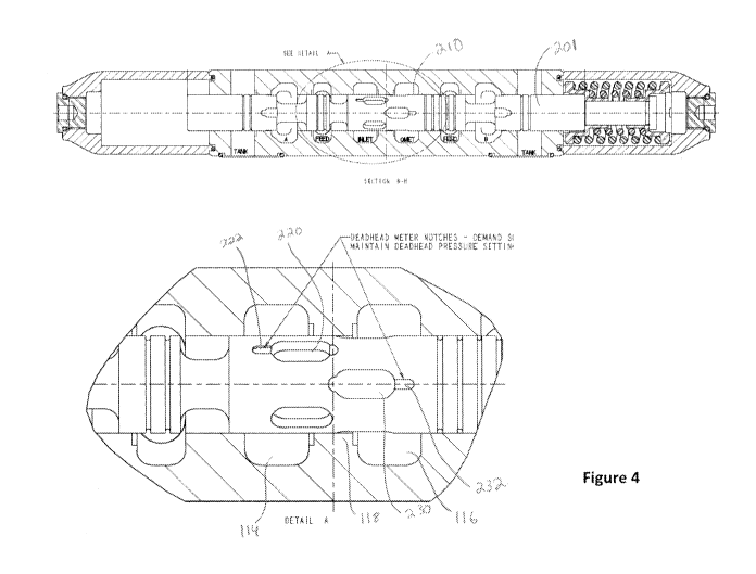
Fig. 4 shows an exemplary PLQ Spool in full with an inset detail of the
notches;
Fig. 5 shows a manually actuated abbreviated version of an exemplary PLQ SPOOL
system
having PLQ functionality at both workports;
Fig. 6 shows a manually actuated full version of an exemplary PLQ SPOOL system
having PLQ
functionality at workport "B" and conventional functionality at workport "A";
Fig. 7 shows an electro-hydraulic actuated full version of an exemplary PLQ
SPOOL system
having PLQ functionality at both workports;
Fig. 8 shows an electro-hydraulically actuated abbreviated version of an
exemplary PLQ SPOOL
system having PLQ functionality at both workports;
Fig. 9 shows an electro-hydraulically actuated abbreviated version of an
exemplary PLQ SPOOL
system having PLQ functionality at workport "A" and conventional functionality
at workport "B";
3
CA 02899595 2015-07-28
WO 2014/121088
PCT/US2014/014176
Fig. 10 shows an electro-hydraulically actuated abbreviated version of an
exemplary PLQ
SPOOL system having PLQ functionality at workport "B" and conventional
functionality at workport
Fig. 11 shows an hydraulically remote actuated abbreviated version of an
exemplary PLQ
SPOOL system having PLQ functionality at both workports;
Fig. 12A-12C show a cross-section of components of an exemplary PLQ SPOOL
system with an
application example;
Fig. 13 shows an exemplary performance graph of a PLQ SPOOL worksection
metering
example;
Fig. 14 shows an exemplary performance graph of a PLQ SPOOL that meters an
actuator to a
stalled state; and
Fig. 15 shows an exemplary performance graph of a PLQ SPOOL worksection that
limits
workport pressure when suddenly actuated to deadhead condition.
Detailed Description
Other pressure relief methods are described below in comparison to exemplary
pressure limited
flow spools (PLQ SPOOL) which are detailed herein.
Conventional "System Load Sense Relief Valve"
A conventional system load sense relief valve is a device which is in parallel
with the maximum
load sense pressure signal. If a workport becomes deadheaded, then the
workport pressure will be
limited to the maximum system pressure dictated by the System Load Sense
Relief Valve. This relief
valve only consumes 0.75-1.00 gpm flow. It is commonly used in Load Sense,
Post Pressure
Compensated, and Pre Pressure Compensated control valves.
In contrast, an exemplary PLQ SPOOL worksection regulates pressure at a
deadheaded workport
at a value less than maximum system pressure. Since the PLQ SPOOL worksection
and other functions
can operate at a lower pressure value, energy efficiency is improved. If a
system load sense relief valve
regulates pressure at a deadheaded workport, then other functions will work at
maximum system pressure
expending unnecessary energy.
"Pre Pressure Compensated Control Valve with Pressure Limiter or Feed Reducer"
Option
A Pre Pressure Compensated Control Valve with Pressure Limiter or Feed Reducer
device
reduces pump output pressure to a preset value that is less than the maximum
hydraulic system pressure.
It works with a pre-load-sensing pressure-reducing type compensator to
regulate workport pressure.
Workport flow is the amount required to maintain the preset pressure value.
These devices do not protect
against shock pressures entering the workport so Full Flow or Clipper Pressure
Relief Valves must be
used. These devices are commonly used in Pre Pressure Compensated control
valves. It is noted that a
Pre Pressure Compensated valve does not have Flow Sharing capability.
4
CA 02899595 2015-07-28
WO 2014/121088
PCT/US2014/014176
A Pre Pressure Compensated valve will automatically assume a conserving low
(pilot) quiescent
flow pressure limiting state whereas an exemplary PLQ SPOOL must be manually
actuated or have
programmed actuation into pilot flow pressure limiting. Pre Pressure
Compensated valves will
automatically convert from a pressure limiting state to outputting a flow in
the range of pilot to the flow
demanded by the control spool to create the pressure limiter pressure setting
if workport flow resistance
is less than the pressure setting. A PLQ SPOOL worksection, in contrast to the
Pre Pressure
Compensated valve, can pressure limit and have flow sharing capability during
pump flow over-demand.
Flow Sharing Post Pressure Compensated Control Valve with Pressure Limitation
Options
Flow Sharing Post Pressure Compensated control valve also has a Pressure
Limited Flow (PLQ)
feature that is Patent Pending per PCT/U52010/057555 and WO 2011/115647 Al,
the disclosure of
which is incorporated by reference herein in its entirety. PLQ will limit
workport pressure to a preset
value less than the maximum hydraulic system pressure using only pilot flow
without negatively
consuming system flow, causing heat generation, and wasting energy. It will
automatically convert from
a pressure limiting state to outputting a flow in the range of pilot to the
flow demanded by the control
spool to create the pressure limiter pressure setting or if workport flow
resistance is less than the pressure
setting. Any application that requires a constant force or torque can use PLQ.
Such a worksection will automatically assume a conserving low (pilot)
quiescent flow pressure
limiting state whereas an exemplary PLQ SPOOL must be manually actuated or
have programmed
actuation into pilot flow pressure limiting. PLQ will automatically convert
from a pressure limiting state
to outputting a flow in the range of pilot to the flow demanded by the control
spool to create the pressure
limiter pressure setting if workport flow resistance is less than the pressure
setting.
A Flow Sharing Post Pressure Compensated control valve can be configured with
a 4 GPM
Maximum Flow Catalog Control Spool used with the Standard Workport relief
valve. The 4 GPM spool
is selected since that is the lowest maximum workport output flow. If the
workport is deadheaded then
the workport relief valve will exhaust the 4 GPM during pressure limitation.
However, 4 GPM may still be wasteful during pressure limitation and may not be
adequate as
Maximum workport output flow. With PLQ SPOOL, a "Maximum" workport output flow
is available in
addition to an energy saving "Pilot" flow used in the final pressure limited
flow stage. The PLQ SPOOL
includes a high "Maximum" flow (for example, 32 gpm) capacity generated by a
low pressure
differential. When fully actuated, the PLQ SPOOL system will limit workport
pressure to a preset value
less than the maximum hydraulic system pressure using only pilot flow without
negatively consuming
system flow, causing heat generation, and wasting energy.
PLQ SPOOL
Initially referring to FIGS. 1 and 2, the illustrated valve assembly 10 and
schematic diagram
show basic valve components and flow paths in a post-compensator arrangement.
5
CA 02899595 2015-07-28
WO 2014/121088
PCT/US2014/014176
The main control spool 12 is shown shifted to the right from a neutral or
closed position.
Hydraulic fluid flows from the inlet passage 14, across the spool to the
pressure compensator poppet 16.
The pressure compensator poppet is forced to shift upward. Fluid flows across
the compensator poppet
into the Qreg core (cast passage) 18 to the load check 20. Load check poppet
is forced open and flow
progresses down across the spool and up to Workport "A" 22. Flow volume is
dictated by the control
spool Inlet to Qmet area that is bounded by the pressure differential of Pin-
Pqm. Qmet area is located in
the flow path between the spool and compensator. Workport (Pwk) and Qreg (Pqr)
pressures are a
function of the resistance to flow at Workport "A". Pqr pressure is sensed by
the Load Sense (LS) Check
24. The LS Check system resolves the Pqr pressures of multiple worksections
into the maximum Qreg
pressure (Pqr max) which is also the conventional Maximum Load Sense (LS)
pressure. Pqr max
pressure is sent to the "load sensing flow and margin pressure source" (LS
pump or fixed pump plus
bypass compensator) and individual worksection post pressure compensator
spring chambers. Pqr max
pressure acting on a compensator poppet causes it to resist and compensate
flow in the conventional post
compensation manner. Qreg = (regulated flow and pressure downstream of
compensator: "Q"= flow,
"reg"= regulated). Qmet = (metered flow & pressure upstream of compensator:
"Q"= flow, "met"=
metered).
An exemplary PLQ SPOOL is a worksection pressure limiting system 100. System
components
include the worksection control spool 201, flow sharing post pressure
compensator 120, and workport
relief valve 130. Referring now to FIG. 3, the worksection control spool 201
position to housing 110
bore 112 relationship is uniquely designed whereby a "Maximum" workport output
flow is available in
addition to a conserving "Pilot" flow used in the final pressure limited flow
stage. High "maximum"
flow (for example, 32 gpm) capacity may be generated by a low pressure
differential. Both the
maximum and pilot flows can be the same or different for the respective "A"
and "B" work positions. A
PLQ SPOOL control spool can have PLQ SPOOL functionality at "A" and "B" or at
either one of "A" or
"B" with a standard configuration at the other position. For non-exhaustive
examples of possible
configurations, please refer to the hydraulic schematics of FIGS. 5-11.
The valve housing/body 110 may have an inlet fluid chamber 114 separated from
a fluid
metering fluid chamber 116 by a dividing portion 118. The chambers may be
fluidly connectable to each
other via the bore 112.
The spool 201 forms with the dividing portion 118 a fluid passageway fluidly
connecting the
inlet chamber with the fluid metering chamber. The fluid passageway can have a
maximum flow
capacity between the chambers or a pilot flow capacity, depending on the
positioning of the spool.
Referring now to Figure 4 in particular, the spool 201 main body has a radial
outer surface 210.
A first recess 220 on the radially outer surface has a first fluid handling
capacity as described above, to
provide a maximum flow. Attached to the first recess is a second recess 222 on
the radially outer surface.
The second recess 222 has a second fluid handling capacity to produce the
lower pilot flow.
Exemplary recesses (or "notches") are shown with the first recess 220 being
radially deeper than
the second recess 222. Also, the first recess 220 is shown as being
circumferentially wider than the
6
CA 02899595 2015-07-28
WO 2014/121088
PCT/US2014/014176
second recess 222. These recesses are used, for example, when the valve is
providing fluid to workport
A224.
When providing fluid to optional workport B 234, a third recess or notch 230
may be provided
on the radially outer surface having a third fluid handling capacity. A fourth
recess 232 on the radially
outer surface may be fluidly connected to the third recess and have a fourth
fluid handling capacity.
Again, the fluid handling capacities may be "maximum" and "pilot",
respectively. These flows for the
workport B may be the same as or different from the fluid capacities of the
first and second recesses.
Again, the exemplary pilot recess 232 is shown as being both radially
shallower and
circumferentially narrower than the main recess 230, although other
arrangements are possible.
Exemplary recess pairs are shown axially and circumferentially offset from
each other, although
other arrangements are possible.
Turning now to Figs. 5-11, exemplary embodiments of the system are shown at
500, 600, 700,
800, 900, 1000, and 1100, respectively. The systems are substantially the same
as the above-referenced
system 100, and consequently the same reference numerals but indexed to their
respective figure numbers
are used to denote structures corresponding to similar structures in the
system. In addition, the foregoing
description of the system 100 is equally applicable to the systems in Figures
5-11, except as noted below.
Moreover, it will be appreciated upon reading and understanding the
specification that aspects of the
systems may be substituted for one another or used in conjunction with one
another where applicable.
Fig. 5 shows a schematic of a manually actuated abbreviated version of an
exemplary PLQ
SPOOL system 500 having PLQ functionality at both workports.
Fig. 6 shows a schematic of a manually actuated full version of an exemplary
PLQ SPOOL
system 600 having PLQ functionality at workport "B" and conventional
functionality at workport "A".
Fig. 7 shows a schematic of an electro-hydraulically actuated full version of
an exemplary PLQ
SPOOL system 700 having PLQ functionality at both workports.
Fig. 8 shows an electro-hydraulically actuated abbreviated version of an
exemplary PLQ SPOOL
system 800 having PLQ functionality at both workports.
Fig. 9 shows an electro-hydraulically actuated abbreviated version of an
exemplary PLQ SPOOL
system 900 having PLQ functionality at workport "A" and conventional
functionality at workport "B".
Fig. 10 shows an electro-hydraulically actuated abbreviated version of an
exemplary PLQ
SPOOL system 1000 having PLQ functionality at workport "B" and conventional
functionality at
workport "A".
Fig. 11 shows an hydraulically remote actuated abbreviated version of an
exemplary PLQ
SPOOL system 1100 having PLQ functionality at both workports.
The flow sharing post pressure compensator design is capable of regulating the
Maximum and
Pilot flows. Workport shock pressure dissipation and lower Pilot flow
meterability are attributes of the
relief valve design. When approximately fully actuated (for example, from
about 88%-100% of
maximum actuation), the PLQ SPOOL system will limit workport pressure to a
preset value less than the
maximum hydraulic system pressure using only pilot flow without negatively
consuming system flow,
7
CA 02899595 2015-07-28
WO 2014/121088
PCT/US2014/014176
causing heat generation, and wasting energy. Exemplary applications for use
with the PLQ SPOOL are
those that require a constant force or torque such as a clamp. The preset
pressure limitation will behave
as a conventional workport relief valve when the PLQ SPOOL is less than fully
actuated. It gives Load
Sense and Flow Sharing Post Pressure Compensated control valves a feature to
compete with a Pre
Pressure Compensated valve device.
In some applications, PLQ SPOOL can be metered to output a selected Maximum
flow and
further metered to slow and control actuator impact at deadhead. Referring now
to FIGS. 12-14, upon
stalling the actuator (e.g., hydraulic cylinder or motor), the control spool
can be advanced fully into
detent (mechanical, hydraulic pressure, or electromagnetic) to engage the
deadhead meter notches and
take advantage of the reduced (for example, 0.9 gpm) pilot flow pressure
limitation to control the applied
force or torque. The energy conserving and negligible reduced pilot
consumption lets essentially all the
pump flow be used by other functions in the system. For a spool stroke less
than full, pressure limitation
is controlled by the workport relief valve by exhausting partial or the
Maximum flow demanded by the
control spool to tank. For partial flow, the remaining flow will go to the
actuator. Flow to the actuator
will increase as the workport pressure reduces as a function of the workport
relief valve pressure override
characteristic. Worksection flow demand will be reduced to the (e.g., 0.9 gpm)
pilot flow once the spool
is fully stroked. Once again, pressure limitation is controlled by the
workport relief valve by exhausting
partial or all the pilot flow to tank. For partial flow, the remaining flow
will go to the actuator (for
example, to replace leakage flow). Flow to the actuator will increase as the
workport pressure reduces as
a function of the workport relief valve pressure override characteristic. It
is best suited if the actuator
retracted-to-stalled transition distance is short. See the hydraulic cylinder
and clamp situation of FIG.
12A-12C. The selected Maximum flow value can be, for example, 4-32 gpm,
resulting in a ratio of
maximum flow to pilot flow of between about 4:1 to about 36:1, although other
flow ratios are possible.
FIG. 14 shows example results from such an operation.
In other applications, PLQ SPOOL may be suddenly and fully actuated from
neutral into detent.
Referring to FIG. 15, maximum flow output is skipped. The actuator will
advance based on the selected
Pilot Flow, and the workport will pressure limit upon achieving the pressure
setting. Pilot Flow is the
workport flow output when the actuator approaches or transitions to and during
the deadhead state.
Although 0.9 gpm Pilot flow at full spool stroke is standard, other pilot flow
values (for example, 0.9 ¨
4.0 gpm) are available.
PLQ SPOOL control spool stroke from the neutral position to the maximum high
pressure A and
B positions (HP"A", HP"B") and flow passage locations may be important.
Shorter spool stroke
prohibits having an ample "Maximum" flow, Flow Meterability before and after
the "Maximum" flow
region, adjustability of Pilot flow, and adequate sealing overlap between high
and low pressure cavities in
the Neutral, HP"A", and HP"B" positions. There must be adequate length for the
Deadhead meter
notches to engage, demand the reduced Pilot Flow, and be tolerance resistant
near the end of stroke. See
FIG.13 for an example of operating characteristics.
8
CA 02899595 2015-07-28
WO 2014/121088
PCT/US2014/014176
Pressure compensator and workport relief valve designs should be able to
acceptably compensate
and pressure limit the low pilot flow, respectively. The post pressure
compensator design should regulate
the maximum and pilot flows. The workport relief valve should provide shock
pressure dissipation in
addition to pilot flow meterability.
An exemplary application for exemplary PLQ SPOOL is a snow plow salt spreader
truck (Plow
Blade Elevation), which may use regulated pressure to generate upward force to
counter gravity acting on
the blade in order to maintain elevation. Further, a snow plow salt spreader
truck (Scraping with Plow)
may use regulated pressure to control the force of the plow blade against the
ground. Still further,
forestry skidder, loader, feller, buncher machines (Clamping and Retaining
Logs) may use regulated
pressure to control the clamping force of the tongs against the logs or trees
while they are being moved.
Moreover, stamping, molding machines (Maximum Press) may use regulated
pressure to control the
force of a ram against the part being made. Additionally, a construction
excavator (Swing) may require
rapid rotational acceleration which can be controlled by limiting torque on a
rotary motor. Further,
impact sensitive and/or automated applications may include a machine actuator
that could be accelerated
to reduce transition time with PLQ SPOOL maximum flow. Then the actuator can
be decelerated by
advancing PLQ SPOOL to the pilot flow stage to reduce impact and provide the
reduced pilot flow
pressure limitation when stalling the actuator. A computer program could
manage this process if the
PLQ SPOOL worksection is configured with standard hydraulic remote (HR) or
electrohydraulic (EH)
spool positioners.
Exemplary PLQ SPOOL systems as described herein are simple, low cost solutions
providing a
special spool in an environment that may be otherwise conventional. Individual
and adjustable workport
A and B pressure settings are easily achieved. Standard workport relief valve
(RV) is used to limit
workport pressure using a small pilot flow. Standard workport RV provides
workport shock suppression
in addition to its pilot flow pressure limitation function. A conventional low
cost pressure compensator
can be used. Pressure limitation fits into a standard worksection assembly and
is a compact package.
Response to Limit Workport Pressure commands is fast because the pressure
compensator is not pilot
operated and the workport relief valve is of a direct acting type. The
worksection "control spool position
to housing bore relationship" is configured to provide a "Maximum" workport
output flow in addition to
an energy saving "Pilot" flow used in the final pressure limited flow stage.
High "Maximum" flow (e.g.,
32 gpm) capacity generated by a low pressure differential distinguishes and
emphasizes the benefits of
this design. Exemplary spools works with both of the common flow sharing post
pressure compensator
types: a) a compensator with isolated pressure signal end chambers, and b) a
compensator with an
isolated load sense pressure signal end chamber and a non-isolated pressure
signal end exposed to inlet
metered flow. Small diameter dampening or flow limiting orifices may not be
required in the PLQ
SPOOL worksection assembly.
Although the invention has been shown and described with respect to a certain
embodiment or
embodiments, it is obvious that equivalent alterations and modifications will
occur to others skilled in the
art upon the reading and understanding of this specification and the annexed
drawings. In particular
9
CA 02899595 2015-07-28
WO 2014/121088
PCT/US2014/014176
regard to the various functions performed by the above described elements
(components, assemblies,
devices, compositions, etc.), the terms (including a reference to a "means")
used to describe such
elements are intended to correspond, unless otherwise indicated, to any
element which performs the
specified function of the described element (i.e., that is functionally
equivalent), even though not
structurally equivalent to the disclosed structure which performs the function
in the herein illustrated
exemplary embodiment or embodiments of the invention. In addition, while a
particular feature of the
invention may have been described above with respect to only one or more of
several illustrated
embodiments, such feature may be combined with one or more other features of
the other embodiments,
as may be desired and advantageous for any given or particular application.
10