Note: Descriptions are shown in the official language in which they were submitted.
CA 02899705 2015-07-29
WO 2014/150626 PCT/US2014/023832
AUTONOMOUS VEHICLE COMPRISING EXTRACORPOREAL
BLOOD TREATMENT MACHINE
FIELD
[0001] The present invention relates to autonomous vehicles and machines
and systems
configured to carry out extracorporeal blood treatment therapies.
BACKGROUND OF THE INVENTION
[0002] As vehicles move more and more toward autonomous operation, vehicle
operators
are gaining more and more freedom to accomplish tasks and concentrate on
matters other than
driving the vehicle. Although portable dialysis machines are known, no vehicle
has been
equipped with a dialysis machine that is interfaced with a vehicle navigation
system or with an
autonomous vehicle control system.
SUMMARY OF THE PRESENT INVENTION
[0003] According to one or more embodiments of the present invention, an
autonomous
vehicle is provided that comprises an autonomous vehicle control system, a
dialysis
machine, and an interface providing an electrical communication between the
dialysis
machine and the autonomous vehicle control system. The autonomous vehicle can
comprise
an automobile, a hybrid car, an airplane, a train, a submarine, a helicopter,
a ship, a boat, a
spacecraft, or any other vehicle. The dialysis machine can be configured to
perform a
dialysis treatment on a patient while the autonomous vehicle is under the
control of the
autonomous vehicle control system. The autonomous vehicle can comprise at
least one
battery for powering one or more components of the autonomous vehicle, and the
interface
can provide an electrical communication between the at least one battery and
the dialysis
machine. The autonomous vehicle can further comprise a vehicle electrical
system, and the
1
CA 02899705 2015-07-29
WO 2014/150626 PCT/US2014/023832
dialysis machine can be hardwired into the vehicle electrical system. The
autonomous
vehicle control system can comprise an input device with which a user can
input a desired
destination. The autonomous vehicle control system can be configured to
calculate the
amount of time required for the autonomous vehicle to reach the desired
destination. The
dialysis machine controller unit can comprise an input device with which a
user can input a
desired prescription therapy, and the dialysis machine controller unit can be
configured to
calculate a rate of treatment that would be required to complete the inputted
prescription
therapy within the amount of time calculated by the autonomous vehicle control
system. The
dialysis machine controller unit can further be configured to determine
whether the
calculated rate of treatment is within acceptable limits, and if so, the
dialysis machine
controller unit can be configured to permit the dialysis machine to carry out
the inputted
prescription therapy. If the controller unit determines that the calculated
rate of treatment is
not within acceptable limits, the dialysis machine controller unit can further
be configured to
prevent the dialysis machine from carrying out the inputted prescription
therapy.
[0004] The present invention also encompasses vehicles that are not
autonomous, but
that include a navigation system, a dialysis machine, and an interface
providing an electrical
communication between the dialysis machine and the navigation system.
[0005] It is to be understood that both the foregoing general description
and the following
detailed description are exemplary and explanatory only and are intended to
provide a further
explanation of the present invention, as claimed.
BRIEF DESCRIPTION OF THE DRAWINGS
[0006] FIG. 1 is a front view of the interior of a vehicle in accordance
with one or more
embodiments of the present invention, showing a dialysis machine mounted, in-
part, in the
vehicle dashboard.
2
CA 02899705 2015-07-29
WO 2014/150626
PCT/US2014/023832
[0007] FIG. 2 is a front view of a vehicle seat back incorporating a
dialysis machine, in
accordance with various embodiments of the present invention.
[0008] FIG. 3 is a flow chart depicting a process for enabling users to
input a prescribed
therapy for dialysis, to be completed while traveling to a destination, and
options that can be
selected by the user if the desired therapy is not available.
[0009] FIG. 4 is a flow chart depicting a process for enabling users to
input a prescribed
therapy to be completed while traveling to a destination, and options that can
be selected by
the user if there is insufficient fuel or power.
[0010] FIG. 5 is a flow chart depicting a process for enabling actions in
response to an
alarm signal, including different actions depending on a state of the alarm
signal.
[0011] FIG. 6 is an exemplary fluid circuit diagram that can be used in a
vehicle and
method in accordance with the present invention;
[0012] FIG. 7 is another exemplary fluid circuit diagram that can be used
in a vehicle
and method in accordance with the present invention;
[0013] FIG. 8 is a schematic of diagram of an exemplary manifold that can
be used in a
vehicle and method in accordance with the present invention;
[0014] FIG. 9 is a front view of an embodiment of a controller unit for a
dialysis system
showing the door open and the manifold installed;
[0015] FIG. 10 is a diagram of an exemplary disconnect monitoring system;
[0016] FIG. 11 is a flowchart defining an exemplary disconnection detection
process;
[0017] FIG. 12 is yet another exemplary fluid circuit diagram that can be
used in a
vehicle and method in accordance with the present invention;
[0018] FIG. 13 is yet another exemplary fluid circuit diagram that can be
used in a
vehicle and method in accordance with the present invention;
[0019] FIG. 14 is yet another exemplary fluid circuit diagram that can be
used in a
3
CA 02899705 2015-07-29
WO 2014/150626 PCT/US2014/023832
vehicle and method in accordance with the present invention;
[0020] FIG. 15 is a flowchart depicting a process for enabling users to
accurately add
additives in a dialysis machine that can be used in a vehicle and method in
accordance with
the present invention;
[0021] FIG. 16 is a schematic diagram showing a disposable kit comprising a
manifold
and a dialyzer attached to a plurality of tubes, which can be used in a
vehicle and method in
accordance with the present invention;
[0022] FIG. 17 is yet another exemplary fluid circuit diagram that can be
used in a
vehicle and method in accordance with the present invention;
[0023] FIG. 18 is yet another exemplary fluid circuit diagram showing a
priming mode
of operation that can be used in a vehicle and method in accordance with the
present
invention; and
[0024] FIG. 19 is a schematic diagram of yet another embodiment of an
exemplary
manifold that can be used in a vehicle and method in accordance with the
present invention.
DETAILED DESCRIPTION OF THE PRESENT INVENTION
[0025] According to one or more embodiments of the present invention, an
autonomous
vehicle is provided that comprises an autonomous vehicle control system, a
dialysis
machine, and an interface providing an electrical communication between the
dialysis
machine and the autonomous vehicle control system. The autonomous vehicle can
comprise
an automobile, a hybrid car, an airplane, a train, a submarine, a helicopter,
a ship, a boat, a
spacecraft, or any other vehicle. The dialysis machine can be configured to
perform a
dialysis treatment on a patient while the autonomous vehicle is under the
control of the
autonomous vehicle control system. The autonomous vehicle can comprise at
least one
battery for powering one or more components of the autonomous vehicle, and the
interface
4
CA 02899705 2015-07-29
WO 2014/150626
PCT/US2014/023832
can provide an electrical communication between the at least one battery and
the dialysis
machine. The autonomous vehicle can further comprise a vehicle electrical
system, and the
dialysis machine can be hardwired into the vehicle electrical system. The
autonomous
vehicle control system can comprise an input device with which a user can
input a desired
destination. The autonomous vehicle control system can be configured to
calculate the
amount of time required for the autonomous vehicle to reach the desired
destination. The
dialysis machine controller unit can comprise an input device with which a
user can input a
desired prescription therapy, and the dialysis machine controller unit can be
configured to
calculate a rate of treatment that would be required to complete the inputted
prescription
therapy within the amount of time calculated by the autonomous vehicle control
system. The
dialysis machine controller unit can further be configured to determine
whether the
calculated rate of treatment is within acceptable limits, and if so, the
dialysis machine
controller unit can be configured to permit the dialysis machine to carry out
the inputted
prescription therapy. If the controller unit determines that the calculated
rate of treatment is
not within acceptable limits, the dialysis machine controller unit can further
be configured to
prevent the dialysis machine from carrying out the inputted prescription
therapy.
[0026] The input device for the autonomous vehicle control system can
comprise a
display screen in the autonomous vehicle, and the input device for the
dialysis machine can
comprise the same display screen or a different display screen. The dialysis
machine can
further comprise a transmitter and a receiver, wherein the transmitter is
configured to
transmit wireless signals pertaining to the dialysis machine, and the receiver
is configured to
receive wireless signals pertaining to the dialysis machine. As such, a
patient can be
constant contact with a monitoring service or clinic, during a therapy.
[0027] The autonomous vehicle can comprise an engine, and the autonomous
vehicle
control system can be configured to maintain the engine in a running condition
while the
CA 02899705 2015-07-29
WO 2014/150626
PCT/US2014/023832
dialysis machine is operating. The autonomous vehicle can comprise a battery-
operated
drive motor configured to move the autonomous vehicle. The autonomous vehicle
can
further comprise a vehicle electrical system, a car battery, an alternator for
charging the car
battery during operation of the vehicle, and a backup battery dedicated to the
dialysis
machine. Then backup battery can be in electrical communication with the
alternator, and
the vehicle electrical system can be configured to charge the backup battery
during operation
of the vehicle. The vehicle electrical system can comprise an ignition switch
and an ignition
switch bypass circuit configured to provide battery power from the backup
battery to the
dialysis machine in the event that the ignition switch is turned off during a
prescription
therapy.
[0028] The dialysis machine can comprise a blood flow circuit comprising: a
blood
pump; a dialyzer; an arterial tube; and a venous tube. The arterial tube and
the venous tube
can be configured to be connectable to a patient blood flow system. The
dialysis machine
can further comprise a dialysate flow circuit comprising: a dialysate pump; a
fresh dialysate
tube; and a spent dialysate tube, wherein the fresh dialysate tube and the
spent dialysate tube
are configured to be connectable to the dialyzer. The dialysis machine can
also comprise an
alarm system configured to transmit a signal, indicative of an alarm
condition, to a receiver.
The receiver can comprise a receiver at a hospital, a receiver at a clinic, a
receiver at a
medical monitoring service, or a receiver at another emergency care center.
The dialysis
machine alarm system can be configured to determine the nearest hospital,
dialysis clinic,
urgent care center, or other emergency care center, and navigate the
autonomous vehicle to
the nearest hospital, dialysis clinic, urgent care center, or other emergency
care center, for
corrective measures. Navigation to an emergency care center can be instigated
if an
emergency state alarm condition is triggered. The dialysis machine alarm
system can
comprise at least one of an arterial chamber transducer and a venous chamber
transducer,
6
CA 02899705 2015-07-29
WO 2014/150626
PCT/US2014/023832
configured for monitoring blood flow pressure changes. In an example, the
dialysis machine
can comprise at least one blood pump, the dialysis machine alarm system can
comprise an
arterial chamber transducer in a blood flow circuit, and the arterial chamber
transducer can
be configured such that, if it registers a pressure change that is outside of
a threshold limit,
the alarm system stops the at least one blood pump. Similarly, the dialysis
machine can
comprise at least one blood pump, the dialysis machine alarm system can
comprise a venous
chamber transducer in a blood flow circuit, and the venous chamber transducer
can be
configured such that, if it registers a pressure change that is outside of a
threshold limit, the
alarm system stops the at least one blood pump.
100291 The dialysis machine can comprise a blood flow circuit comprising: a
blood
pump; a dialyzer; an arterial tube configured to be connectable to a patient
blood flow
system; a venous tube configured to be connectable to a patient blood flow
system; and an
emergency state alarm system operably configured to indicate an emergency
condition. The
emergency state alarm system can be configured such that, upon activation, the
autonomous
vehicle control system navigates the autonomous vehicle to a hospital, a
dialysis clinic, an
urgent care center, or another emergency care center, for corrective measures.
For example,
the autonomous vehicle control system can be configured such that, upon
activation of the
emergency state alarm system, the autonomous vehicle control system determines
the
nearest emergency care center, and navigates the autonomous vehicle to the
nearest
emergency care center, for corrective measures. The autonomous vehicle control
system can
be configured such that, upon activation of the emergency state alarm system,
the
autonomous vehicle control system determines the nearest emergency care
center, sends a
notification to the nearest emergency care center so determined, and navigates
the
autonomous vehicle to the nearest emergency care center for corrective
measures, the
notification pertaining to the emergency condition that triggered the
activation of the
7
CA 02899705 2015-07-29
WO 2014/150626
PCT/US2014/023832
emergency state alarm system.
[0030] The dialysis machine can further comprise an arterial tube pressure
sensor, a
venous tube pressure sensor, and an alarm system configured to indicate an
alarm condition
when one or both of the arterial tube pressure sensor and the venous tube
pressure sensor
senses a pressure that exceeds a maximum respective threshold value or that
drops below a
minimum respective threshold value. The dialysis machine can comprise at least
one blood
pump and an alarm system, wherein the alarm system is configured to (1) stop
operation of
at least one blood pump in response to receiving a low level alarm signal, and
(2) navigate
the autonomous vehicle to the nearest emergency care center in response to
receiving an
emergency state alarm signal.
[0031] The autonomous vehicle can further comprise an engine, a fuel source
for the
engine, a fuel sensor configured to sense the amount of fuel available for the
engine, and a
dialysis controller for the dialysis machine. The dialysis controller can
comprise a user
interface configured to enable a user to input a prescription therapy to the
dialysis machine.
The interface between the dialysis machine and the autonomous vehicle control
system can
comprise an electrical communication between the fuel sensor and the dialysis
controller.
The fuel sensor can be configured to send a signal to the dialysis controller
indicating the
amount of fuel available to power the engine, and the dialysis controller can
be configured
to notify the user if there is insufficient fuel to power the engine for the
amount of time that
would be required to carry out the prescription therapy. The dialysis
controller can be
configured to calculate the amount of fuel that would be required to operate
the autonomous
vehicle for a period of time required to carry out the prescription therapy,
and then notify the
user if there is insufficient fuel to power the engine for the amount of time
that would be
required to carry out the prescription therapy. The dialysis controller can be
configured to
calculate the amount of fuel based on a measured current rate of consumption
and based on
8
CA 02899705 2015-07-29
WO 2014/150626
PCT/US2014/023832
a predicted rate of consumption that would be required to operate the
autonomous vehicle
and the dialysis machine together for the amount of time that would be
required to carry out
the prescription therapy. The dialysis controller can further be configured to
prevent the
dialysis machine from carrying out the prescription therapy if there is
insufficient fuel to
power the engine for the amount of time that would be required to carry out
the prescription
therapy.
[0032] The autonomous vehicle can comprise a battery-operated motive
engine, a
battery configured to supply battery power to the engine, a battery sensor
configured to
sense the amount of battery power available for the engine, and a dialysis
controller for the
dialysis machine. The dialysis controller can comprise a user interface
configured to enable
a user to input a prescription therapy to the dialysis machine. The interface
between the
dialysis machine and the autonomous vehicle control system can comprise an
electrical
communication between the battery sensor and the dialysis controller, and the
battery sensor
can be configured to send a signal to the dialysis controller indicating the
amount of battery
power available to power the engine. The dialysis controller can be configured
to notify the
user if there is insufficient battery power to power the engine for the amount
of time that
would be required to carry out the prescription therapy. The dialysis
controller can be
configured to calculate the amount of battery power that would be required to
operate the
autonomous vehicle for a period of time required to carry out the prescription
therapy, and
then notify the user if there is insufficient battery power to power the
engine for the amount
of time that would be required to carry out the prescription therapy.
Moreover, the dialysis
controller can be configured to calculate the amount of battery power based on
a measured
current rate of consumption and based on a predicted rate of consumption that
would be
required to operate the autonomous vehicle and the dialysis machine together
for the amount
of time that would be required to carry out the prescription therapy. The
dialysis controller
9
CA 02899705 2015-07-29
WO 2014/150626
PCT/US2014/023832
can further be configured to prevent the dialysis machine from carrying out
the prescription
therapy if there is insufficient battery power to power the engine for the
amount of time that
would be required to carry out the prescription therapy.
[0033] The dialysis machine can comprise a recirculating dialysate fluid
circuit and a
sorbent cartridge in fluid communication with the recirculating dialysate
fluid circuit. The
autonomous vehicle can comprise an engine and an engine cooling system. The
dialysis
machine can comprise at least one fluid flow path, and the interface can be
configured to use
heat from the engine cooling system to heat one or more fluids flowing through
the at least
one fluid flow path. The engine cooling system can comprise an engine coolant
flow path,
and the interface can provide a heat-exchange communication between the engine
coolant
flow path and the at least one fluid flow path of the dialysis machine. The at
least one fluid
flow path of the dialysis machine can comprise a dialysate flow path and the
interface can
comprise a heat exchanger that is in thermal communication with the engine
coolant flow
path and the dialysate flow path. The dialysis machine can comprise a
dialysate fluid flow
path and a heater that is in thermal communication with the dialysate fluid
flow path to heat
dialysate fluid in the dialysate fluid flow path. The heater can comprise a
resistance heater,
an electrical heater, a radiant heater, a Peltier heater, or the like.
[0034] According to one or more embodiments of the present invention, an
autonomous
vehicle is provided that comprises a vehicle interior, an autonomous vehicle
control system,
a dialysis machine, and an interface providing an electrical communication
between the
dialysis machine and the autonomous vehicle control system. The dialysis
machine can be
configured to perform a dialysis treatment on a patient while the autonomous
vehicle is
under the control of the autonomous vehicle control system. The dialysis
machine can
comprise, for example: a control unit; and a receiver fixedly attached to the
vehicle interior
and configured to receive disposable dialysis equipment. The autonomous
vehicle can
CA 02899705 2015-07-29
WO 2014/150626
PCT/US2014/023832
further comprise a vehicle electrical system and the dialysis machine can be
hardwired into
the vehicle electrical system. The dialysis machine can include disposable
dialysis
equipment, for example, comprising a molded plastic manifold defining a first
flow path
and a second flow path that is fluidically isolated from the first flow path.
The molded
plastic manifold can be received by the receiver. The disposable dialysis
equipment can
further comprise a dialyzer and the molded plastic manifold can be bonded to a
plurality of
tubes, wherein at least two of the tubes are in fluid communication with the
dialyzer. A
dialyzer mount can be fixedly attached to the vehicle interior and configured
to fixedly
secure the dialyzer with respect to the dialysis machine. The disposable
dialysis equipment
can further comprise a sorbent cartridge, and the molded plastic manifold can
be bonded to a
plurality of tubes, at least two of which are in fluid communication with the
sorbent
cartridge. A cartridge mount can be fixedly attached to the vehicle interior
and configured to
fixedly secure the sorbent cartridge with respect to the dialysis machine.
[0035] The
dialysis machine can further comprise: a door having an interior face; and a
housing built into the interior of the vehicle and including a panel. The
housing and the
panel can be configured so that together they define a recessed region adapted
to receive the
interior face of the door. The receiver can be fixedly attached to the panel.
The panel can be
configured to provide access to a plurality of pumps, and the dialysis machine
can further
comprise pumps, for example, at least one blood pump and at least one
dialysate pump. The
pumps can be operably positioned in substantially parallel alignment with one
another, and
the panel can be configured to provide access to the pumps. The interior face
of the door
can comprise pump shoes that align with the pumps when the door is in a closed
position.
The door can have an exterior face and the control unit can be mounted on the
exterior face
of the door.
[0036] The
dialysis machine can further comprise a surface for receiving a container of
11
CA 02899705 2015-07-29
WO 2014/150626
PCT/US2014/023832
fluid. The surface can be built into a floor or a seat of the autonomous
vehicle. A scale can
be integrated into the surface and configured to weigh a container of fluid
disposed on the
surface. A heater can be provided in thermal communication with the surface,
and a
conductivity sensor can be provided in electromagnetic communication with the
surface. In
some cases, the autonomous vehicle comprises a dash board and the control unit
is mounted
in or on the dash board. The control unit can comprise a graphical user
interface, and the
graphical user interface can be mounted in or on the dash board. The dialysis
machine can
further comprise a plurality of connectors, and an electronic circuit element.
The electronic
circuit element can comprise a processor module, a data acquisition module in
electrical
communication with the processor module, and an interface module in electronic
communication with the data acquisition module. The electronic circuit element
can
comprise a video module, a touch panel element in electrical communication
with the video
module, a pulse display, one or more pressure displays, an electrocardiogram
display, a
combination thereof, or the like. The plurality of connectors can comprise a
blood pressure
device input, a pulse device input, an EKG device input, a combination
thereof, or the like.
The autonomous vehicle can further comprise a catch basin, the vehicle
interior can
comprise a floor, the dialysis machine can comprise a plurality of connectors,
the catch
basin can be secured to the floor, and the catch basin can be positioned with
respect to the
dialysis machine to catch liquid that drips from the connectors in the event
that liquid drips
from one or more of the plurality of connectors. The catch basin can be
removably secured
to the floor. The catch basin can be removably secured to a seat in the
vehicle.
[0037] According to one or more embodiments of the present invention, the
vehicle can
be, but is not necessarily, an autonomous vehicle. Although referred to below
as a non-
autonomous vehicle to distinguish from some of the embodiments described
above, it is to
be understood that the features described below could similarly be
incorporated into an
12
CA 02899705 2015-07-29
WO 2014/150626
PCT/US2014/023832
autonomous vehicle and doing so is well within the scope of the present
invention.
[0038] The non-autonomous vehicle can comprise an automobile, a hybrid car,
an
airplane, a train, a submarine, a helicopter, a ship, a boat, a spacecraft, or
the like. The
vehicle can comprise a vehicle navigation system, a dialysis machine, and an
interface
providing an electrical communication between the dialysis machine and the
vehicle
navigation system. The dialysis machine can be configured to perform a
dialysis treatment
on a patient while the vehicle is operating. The dialysis machine can
comprise: a controller;
a door having an interior face; a housing built into the interior of the
vehicle and including a
panel, wherein the housing and the panel define a recessed region that faces
the interior face
of the door; and a disposables circuit receiver attached to the panel. The
vehicle can further
comprise a vehicle electrical system, and the dialysis machine can be
hardwired into the
vehicle electrical system. The vehicle can comprise at least one battery for
powering one or
more components of the vehicle, and the interface can provide an electrical
communication
between the at least one battery and the dialysis machine.
[0039] The vehicle navigation system can comprise an input device with
which a user
can input a desired destination. The vehicle navigation system can be
configured to
calculate the amount of time required for the vehicle to reach the desired
destination. The
dialysis machine can comprise an input device with which a user can input a
desired
prescription therapy. The dialysis machine can also comprise a control unit
configured to
calculate a rate of treatment that would be required to complete the inputted
prescription
therapy within the amount of time calculated by the vehicle navigation system.
The dialysis
machine control unit can further be configured to determine whether the
calculated rate of
treatment is within acceptable limits, and if so, the dialysis machine control
unit can be
configured to permit the dialysis machine to carry out the inputted
prescription therapy. If
the control unit determines that the calculated rate of treatment is not
within acceptable
13
CA 02899705 2015-07-29
WO 2014/150626
PCT/US2014/023832
limits, the dialysis machine control unit can be configured to prevent the
dialysis machine
from carrying out the inputted prescription therapy.
[0040] The dialysis machine can further comprise a transmitter and a
receiver. The
transmitter can be configured to transmit wireless signals pertaining to the
dialysis machine,
and the receiver can be configured to receive wireless signals pertaining to
the dialysis
machine. The vehicle can comprise a vehicle electrical system, a battery, an
alternator for
charging the battery during operation of the vehicle, and a backup battery
dedicated to the
dialysis machine. The backup battery can be in electrical communication with
the alternator
and the vehicle electrical system can be configured to charge the backup
battery during
operation of the vehicle. The vehicle electrical system can comprise an
ignition switch and
an ignition switch bypass circuit configured to provide battery power from the
backup
battery to the dialysis machine in the event that the ignition switch is
turned off.
[0041] Similar to the autonomous vehicles discussed above, the dialysis
machine in the
non-autonomous vehicle can also comprise an emergency state alarm system
operably
configured to indicate an emergency condition. Upon activation of the
emergency state
alarm system, the vehicle navigation system can be caused to navigate the
vehicle to an
emergency care center, for corrective measures. Upon activation of the
emergency state
alarm system, the vehicle navigation system can determine the nearest
emergency care
center and navigate the vehicle to the nearest emergency care, center for
corrective
measures. In some cases, upon activation of the emergency state alarm system,
the vehicle
control system can determine the nearest emergency care center, send a
notification to the
nearest emergency care center so determined, and navigate the vehicle to the
nearest
emergency care center, for corrective measures. The notification can pertain
to the
emergency condition that triggered the activation of the emergency state alarm
system.
[0042] The dialysis machine can further comprise an arterial tube pressure
sensor, a
14
CA 02899705 2015-07-29
WO 2014/150626
PCT/US2014/023832
venous tube pressure sensor, and an alarm system configured to indicate an
alarm condition
when one or both of the arterial tube pressure sensor and the venous tube
pressure sensor
senses a pressure that exceeds a maximum respective threshold value or that
drops below a
minimum respective threshold value. The dialysis machine can comprise at least
one blood
pump, and such an alarm system. The alarm system can be configured to (1) stop
operation
of the at least one blood pump in response to receiving a low level alarm or a
high level
alarm signal, and (2) navigate the vehicle to the nearest emergency care
center in response to
receiving an emergency state alarm signal. The dialysis machine alarm system
can further be
, configured to transmit a signal, indicative of an alarm condition, to a
receiver. The receiver
can comprise a receiver at a hospital, a receiver at a clinic, a receiver at a
medical
monitoring service, or a receiver at another emergency care center. The
dialysis machine can
include an alarm system that comprises at least one of an arterial chamber
transducer and a
venous chamber transducer, in a blood flow path, which are configured for
monitoring
blood flow pressure changes.
[0043] The vehicle can comprise an engine, a fuel source for the engine, a
fuel sensor
configured to sense the amount of fuel available for the engine, and a
dialysis control unit
for the dialysis machine. The dialysis control unit can comprise a user
interface configured
to enable a user to input a prescription therapy to the dialysis machine, the
interface between
the dialysis machine and the vehicle navigation system can comprise an
electrical
communication between the fuel sensor and the dialysis control unit. The fuel
sensor can be
configured to send a signal to the dialysis control unit indicating the amount
of fuel
available to power the engine. The dialysis control unit can be configured to
notify the user
if there is insufficient fuel to power the engine for the amount of time that
would be required
to carry out the prescription therapy. In some cases, the dialysis control
unit can be
configured to calculate the amount of fuel that would be required to operate
the vehicle for a
CA 02899705 2015-07-29
WO 2014/150626
PCT/US2014/023832
period of time required to carry out the prescription therapy, and then notify
the user if there
is insufficient fuel to power the engine for the amount of time that would be
required to
carry out the prescription therapy. The dialysis control unit can be
configured to calculate
the amount of fuel based on a measured current rate of consumption and based
on a
predicted rate of consumption that would be required to operate the vehicle
and the dialysis
machine together for the amount of time that would be required to carry out
the prescription
therapy. The dialysis control unit can be configured to prevent the dialysis
machine from
carrying out the prescription therapy if there is insufficient fuel to power
the engine for the
amount of time that would be required to carry out the prescription therapy.
[0044] In cases where the vehicle comprises a battery-operated motive
engine, a battery
is provided to supply battery power to the engine. A battery sensor can be
configured to
sense the amount of battery power available for the engine, and a dialysis
control unit for the
dialysis machine can comprise a user interface configured to enable a user to
input a
prescription therapy to the dialysis machine. The interface between the
dialysis machine
and the vehicle navigation system can comprise an electrical communication
between the
battery sensor and the dialysis control unit. The battery sensor can be
configured to send a
signal to the dialysis control unit indicating the amount of battery power
available to power
the engine, and the dialysis control unit can be configured to notify the user
if there is
insufficient battery power to power the engine for the amount of time that
would be required
to carry out the prescription therapy. The dialysis control unit can be
configured to calculate
the amount of battery power that would be required to operate the vehicle for
a period of
time required to carry out the prescription therapy, and then notify the user
if there is
insufficient battery power to power the engine for the amount of time that
would be
required. The dialysis control unit can be configured to calculate the amount
of battery
power based on a measured current rate of consumption and based on a predicted
rate of
16
CA 02899705 2015-07-29
WO 2014/150626 PCT/US2014/023832
consumption that would be required to operate the vehicle and the dialysis
machine together
for the amount of time that would be required to carry out the prescription
therapy. The
dialysis control unit can further be configured to prevent the dialysis
machine from carrying
out the prescription therapy if there is insufficient battery power to power
the engine for the
amount of time that would be required to carry out the therapy.
[0045] Similar to the autonomous vehicles discussed above, the non-
autonomous
vehicle can further comprise a catch basin. The vehicle interior can comprise
a floor, the
dialysis machine can comprise a plurality of connectors, and the catch basin
can be secured
to the floor in a position with respect to the dialysis machine such that the
catch basin can
catch any liquid that drips from the connectors in the event that one or more
of the
connectors leaks. The catch basin can be removably secured to the floor,
removably secured
to a seat in the vehicle, removably secured in a trunk of the vehicle, or the
like.
[0046] The vehicle can further comprise a dash board, and the dialysis
machine can
comprise a graphical user interface mounted in or on the dash board. The
dialysis machine
can further comprise a front panel having associated therewith an electronic
circuit element.
The electronic circuit element can comprise a processor module, a data
acquisition module
in electrical communication with the processor module, an interface module in
electronic
communication with the data acquisition module, a video module, a touch panel
element in
electrical communication with the video module, a pulse display, an EKG
display, a
combination thereof, or the like. The dialysis machine can further comprise a
front panel
having associated therewith a plurality of connectors comprising a blood
pressure device
input, a pulse device input, an EKG device input, a combination thereof, or
the like.
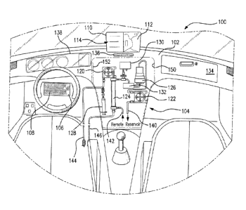
[0047] With reference to the drawings, FIG. 1 is a front view of an
interior 100 of a
vehicle in accordance with one or more embodiments of the present invention.
While the
vehicle can be an autonomous vehicle, it does not have to be. The vehicle
includes a
17
CA 02899705 2015-07-29
WO 2014/150626 PCT/US2014/023832
dashboard 102, a dialysis machine 104 mounted in or on dashboard 102, and a
user interface
106 that can be used for programming dialysis machine 104 and a vehicle
navigation system.
User interface 106 can include a keyboard 108, a display screen 110, a
microphone, and quick
control buttons 136 for controlling display screen 110. Display screen 110 can
be a shared
display screen for displaying user prompts, inquiries, instructions, and the
like information.
Display screen 110 can be split, for example, as a function of one or more of
quick control
buttons 136. Navigation information 112 and dialysis therapy information 114
can
simultaneously be displayed by using a split screen function. One or more
buttons or features
can be included to gain access to a voice-activation system that can be used
to input
information. The information can include, for example, vehicle navigation
instructions,
dialysis therapy instructions, other information, a combination thereof, and
the like.
[0048] Dialysis machine 104 can comprise a blood pump 120, a dialysate pump
122, a
dialyzer 124, a sorbent cartridge 126, an anti-coagulant injection system 128,
a pressure sensor
130, and a drip chamber 132. One or more of the dialysis machine components
can be
provided as a disposable. Many of the dialysis machine components can be
provided together
as a disposable kit.
[0049] The vehicle in which dialysis machine 104 is mounted can include a
navigation
system for which information can be displayed on display screen 110. In FIG.
1, navigation
information 112 is displayed on right-hand side of display screen 110, and
display screen 110
is configured for a split screen display. The left-hand side of display screen
110 can display
information, user prompts, inquiries, instructions, and the like, pertaining
to a dialysis therapy
to be carried out by dialysis machine 104.
[0050] A door, not shown, can be used to encase and protect dialysis
machine 104 within
a recess 150 that is provided in dashboard 102. Access to dialysis machine 104
can be gained,
for example, by a lock on the door, or by a latch, for example, that includes
a handle disposed
18
CA 02899705 2015-07-29
WO 2014/150626 PCT/US2014/023832
within a glove box 134.
[0051] The dialysate circuit of dialysis machine 104 can include a to-
reservoir line 140
and a from-reservoir line 142 that are in fluid communication with a remote
reservoir (not
shown). The remote reservoir can be disposed, for example, in glove box 134,
in a trunk of the
vehicle, in a back seat of the vehicle, in the passenger seat, mounted
elsewhere in the
dashboard, or in another suitable location of the vehicle. The reservoir can
be operationally
associated with a heater, a scale, or both. For example, the reservoir can be
disposed on top of
a heater and a scale. Dialysis machine 104 can further include a from-patient
venous catheter
line 144 and a to-patient arterial catheter line 146 for connection of
dialysis machine 104 to a
patient. Venous catheter line 144 and arterial catheter line 146 can be
included in a disposables
kit, for example, in a kit that further includes dialyzer 124, sorbent
cartridge 126, anti-
coagulant injection system 128, drip chamber 132, and interconnecting tubing.
Any number of
different disposables kits can be configured to operate in conjunction with
dialysis machine
104, and many are described below. Different kits can be provided to carry out
different
therapies.
[0052] Information pertaining to operation of the vehicle can be displayed
in a vehicle
operation information display panel 138. The information can include, for
example, speed,
rpm, oil temperature, oil pressure, outside temperature, and the like.
According to one or more
embodiments of the present invention, the vehicle navigation system and
dialysis machine 104
can be interfaced such that a dialysis therapy can be carried out on a patient
while the vehicle
transports the patient to a destination.
100531 FIG. 2 is a front view of a vehicle seat 200 in accordance with one
or more
embodiments of the present invention. Vehicle seat 200 includes a dialysis
machine 204
incorporated therein. Dialysis machine 204 can be set in, or wholly or
partially recessed
within, a recess 250 formed in vehicle seat 200. In the embodiment depicted,
dialysis machine
19
CA 02899705 2015-07-29
WO 2014/150626
PCT/US2014/023832
204 is recessed into the back of vehicle seat 200, although other positions
can be used.
[0054] While the vehicle seat can be provided in an autonomous vehicle, the
vehicle does
not have to be autonomous. Dialysis machine 204 can be provided with a user
interface, and
in an exemplary embodiment, the user interface can comprise a touch screen,
for example,
display screen 210 can also be used as a touch screen input device that can be
used for
programming dialysis machine 204. Dialysis machine 204 can be interfaced with
a vehicle
navigation system so that a therapy would not be authorized if the vehicle is
expected to arrive
at a desired destination before a requested therapy can be completed. Although
not shown, the
user interface can also or instead include a keyboard, a microphone, a joy
stick, a combination
thereof, or the like.
[0055] Display screen 210 can be controlled, at least in-part, by quick
control buttons 236.
Display screen 210 can be a shared display screen for displaying user prompts,
inquiries,
instructions, and the like information. Display screen 210 can be split, for
example, as a
function of one or more of quick control buttons 236. Although only dialysis
therapy
information 214 is displayed on display screen 210, in FIG. 2, it is to be
understood that
navigation information and dialysis therapy information can simultaneously be
displayed by
using a split screen function. One or more buttons or features can be included
to gain access to
a voice-activation system that can be used to input information. The
information can include,
for example, vehicle navigation instructions, dialysis therapy instructions,
other information, a
combination thereof, and the like.
[0056] Dialysis machine 204 can comprise a blood pump 220, a dialysate pump
222, a
dialyzer 224, a sorbent cartridge 226, an anti-coagulant injection system 228,
a pressure sensor
230, and a drip chamber 232. One or more of the dialysis machine components
can be
provided as a disposable. Many of the dialysis machine components can be
provided together
as a disposable kit.
CA 02899705 2015-07-29
WO 2014/150626 PCT/US2014/023832
[0057] The vehicle in which vehicle seat 200 and dialysis machine 204 are
mounted can
include a navigation system for which information can be displayed on display
screen 210, for
example, navigation information can be displayed on a right-hand side of
display screen 210
while therapy information can be displayed on the left-hand side of display
screen 210. The
information can include user prompts, inquiries, instructions, warnings, alarm
signals, and the
like, pertaining to a dialysis therapy to be carried out, or being carried
out, by dialysis machine
204.
[0058] A door, not shown, can be used to encase and protect dialysis
machine 204 within
recess 250. Access to dialysis machine 204 can be gained, for example, by a
lock on the door,
or by a latch, for example, that includes a handle. A hinge can be provided
spaced from, but
close to, the edge 252 of vehicle seat 200. The hinge can be provided to
hingedly attach the
door to recess 250 or elsewhere to vehicle seat 200.
[0059] The dialysate circuit of dialysis machine 204 can include a to-
reservoir line 240
and a from-reservoir line 242 that are in fluid communication with a reservoir
260. The
reservoir can alternatively be disposed, for example, in a glove box, under
vehicle seat 200, in
a trunk of the vehicle, in a back seat of the vehicle, in a passenger seat of
the vehicle, in a
cargo hold, or in another suitable location of the vehicle. The reservoir can
be operationally
associated with a heater, a scale, or both. For example, as shown, a heating
and weighing
system 270 can be provided underneath reservoir 260, for heating and weighing
the contents of
reservoir 260. A conductivity sensor 272 can also be provided for measuring
the conductivity
of dialysate in the reservoir.
[0060] Dialysis machine 204 can further include a from-patient venous
catheter line 244
and a to-patient arterial catheter line 246 for connection of dialysis machine
204 to a patient.
The patient can sit, for example, in a seat directly behind vehicle seat 200,
during therapy.
Venous catheter line 244 and arterial catheter line 246 can be included in a
disposables kit, for
21
CA 02899705 2015-07-29
WO 2014/150626 PCT/US2014/023832
example, in a kit that further includes dialyzer 224, sorbent cartridge 226,
anti-coagulant
injection system 228, drip chamber 232, and interconnecting tubing. Any number
of different
disposables kits can be configured to operate in conjunction with dialysis
machine 204, and
many are described below. Different kits can be provided to carry out
different therapies.
[0061] FIG. 3 is a flow chart depicting a process for enabling a user to
input a prescribed
therapy for dialysis, which is to be completed while the user is traveling to
a destination.
Initially, a user can input a prescription therapy to be carried out, and a
destination. Although
either the therapy or the destination can be input first, FIG. 3 depicts
inputting the prescription
therapy as a first step 300, followed by a step 302 for inputting a
destination. The therapy
and/or destination can be input using voice activation, a keyboard, a touch
screen, a joystick, a
combination thereof, or the like. The vehicle navigation system can be
provided with a
processor and a global positioning system (GPS), which together can be used to
calculate an
arrival time, as depicted in step 304. During travel, adjustments to the
calculated arrival time
can be made and one or more revised arrival times can be displayed.
[0062] As depicted in step 306, the processor can determine, based on the
inputted
prescription therapy and the calculated arrival time, whether the requested
therapy can be
completed before the arrival time. If so, a dialysis machine display screen
can be used to
display a message such as "Press START to proceed with therapy," as depicted
in step 308. If
the processor determines that the requested therapy cannot be completed before
the arrival
time, in step 306, then the display can be powered to show a message such as
"Insufficient
time until arrival to complete therapy," as depicted in step 310. If the
processor, or an
associated data store, memory, or other source of data, indicates that
optional therapies are
available that can be completed before the calculated arrival time, the
processor can power the
display to show a message such as "Show therapies that can be completed before
arrival
time?", as depicted in step 312. If there are alternative therapies available,
the system can be
22
CA 02899705 2015-07-29
WO 2014/150626 PCT/US2014/023832
configured to display the different options and the user can be prompted to
select one of the
alternative therapies, or cancel programming. If the user does not want to see
a listing of
alternative therapies that are available, the user can input "No" in response
to the query of step
314, and in response, the system can be configured to display a message such
as "Press GO to
proceed to destination," as depicted in step 316.
[0063] If alternative therapies are available and the user wants to see
them, the user can
input a YES command in response to the query of step 314 and the processor can
calculate and
display the alternative therapies that can be completed before the arrival
time. Calculating the
therapies is depicted in step 318 and displaying the therapies is depicted in
step 320. Once the
alternative therapies are displayed, the user can be prompted to select one of
the alternative
therapies, and the selection can be input in a step 322. Once an alternative
therapy is selected,
the display can be powered to show a message such as "Press START to proceed
with
therapy," as depicted in step 324.
[0064] FIG. 4 is a flow chart depicting a process for enabling a user to
input a prescribed
therapy for dialysis, to be completed while traveling to a destination. In the
process depicted in
FIG. 4, a vehicle information system is interfaced with a dialysis machine
control system and a
processor can be used to determine whether there is sufficient fuel, battery
power, other energy
source, or a combination thereof, to operate the vehicle for the length of
time that would be
required to complete the requested dialysis therapy. While many energy sources
can be used,
the sources are exemplified as fuel (or power) in FIG. 4. As depicted in FIG.
4, a prescription
for a dialysis therapy can be input into a processor, as shown in step 400.
The processor can
then calculate, based on the amount of available fuel, battery power, other
energy source, or
combination thereof, whether the vehicle has sufficient fuel, battery power,
energy sources , or
the like, to operate for the necessary length of time. The calculating is
depicted in step 402.
Once the fuel and/or battery power has been compared to the amount needed to
complete the
23
CA 02899705 2015-07-29
WO 2014/150626
PCT/US2014/023832
requested prescription therapy, the processor then can respond to the query
shown in step 404,
that is, whether the vehicle has sufficient fuel and/or battery power. If
there is sufficient fuel
and/or battery power, the processor can send a signal to display a message
such as, "Press
START to proceed with therapy," as depicted in step 406.
[0065] If the processor determines that the requested therapy cannot be
completed based
on the available fuel or power, in step 404, then the display can be powered
to show a message
such as "Insufficient fuel (or power) to complete therapy," as depicted in
step 408. If the
processor, or an associated data store, memory, or other source of data,
indicates that optional
therapies are available that can be completed with the available fuel or
power, the processor
can power the display to show a message such as "Show therapies that can be
completed with
available fuel (or power)?", as depicted in step 410. If there are alternative
therapies available,
the system can be configured to display the different options and the user can
be prompted to
select one of the alternative therapies, or cancel programming. If the user
does not want to see
a listing of alternative therapies that are available, the user can input "No"
in response to the
query of step 412, and in response, the system can be configured to display a
message such as
"Therapy canceled," as depicted in step 414.
[0066] If alternative therapies are available and the user wants to see
them, the user can
input a YES command in response to the query of step 412 and the processor can
calculate and
display the alternative therapies that can be completed based on the available
fuel or power.
Calculating the therapies is depicted in step 416 and displaying the therapies
is depicted in step
418. Once the alternative therapies are displayed, the user can be prompted to
select one of the
alternative therapies, and the selection can be input in a step 420. Once an
alternative therapy
is selected, the display can be powered to show a message such as "Press START
to proceed
with therapy," as depicted in step 422.
[0067] FIG. 5 is a flow chart depicting a process for enabling one or more
dialysis
24
CA 02899705 2015-07-29
WO 2014/150626 PCT/US2014/023832
machine and/or vehicle actions in response to an alarm signal. As described in
greater detail
below, the dialysis machine incorporated in the vehicle can be provided with
an alarm system
configured to generate one or more alarm signals indicative of one or more,
respective, alarm
states. As with conventional dialysis machines, the dialysis machine can be
provided with
sensors for detecting leaks, occlusions, air bubbles, loss of pressure,
disconnect, elevated
pressure, blood pulse, electrocardiogram, or other conditions and parameters.
In many cases, a
low level alarm signal can be generated for conditions that can be easily
corrected by the user.
In some cases, however, a more serious condition can trigger an emergency
state alarm signal,
for example, indicative of a grave situation needing immediate attention and
which the user
may not be able to correct. An exemplary condition that might trigger an
emergency state
alarm signal would be a lack of pulse, a lack of heart beat, a lack of
arterial pressure, or a
vehicle collision. As shown in FIG. 5, the alarm system can be programmed to
receive an
alarm signal in step 500, and determine whether the alarm signal is an
emergency state signal,
as depicted in step 502. If the alarm signal is an emergency state alarm
signal, the alarm
system can be configured to calculate the nearest emergency care center, as
depicted in FIG.
504, and navigate the vehicle to the nearest emergency care center, as
depicted in step 506.
The alarm system can display a message such as "Proceeding to nearest
emergency care
center," as depicted in step 508. The alarm system can further be configured
to provide
additional information, for example, by displaying the name, address, and
phone number of
the nearest emergency care center to which the vehicle is being navigated, as
depicted is step
510. The alarm system can be configured to automatically call a help hotline
or 911.
[0068] If, the alarm system determines that the alarm signal is not for an
emergency state,
in step 502, then the alarm system can be configured to stop the blood pump as
depicted in
step 512 and display a message such as "Check connections, check for
occlusion, check for air
bubbles," as depicted in step 514. The user is thus prompted to take
corrective action as
CA 02899705 2016-07-27
depicted in step 516, for example, to reestablish a connection, to remove an
air bubble, to adjust
the position of a catheter in a vein or artery, or the like. After taking the
corrective action, the
user can then enter a "Proceed" command and the alarm system can then test for
the condition
that caused the low level alarm signal. Testing for the condition is depicted
in step 518. If the
condition is corrected, as queried in step 520, then the alarm system can be
reset as depicted in
step 522. If, however, the condition is not corrected ill response to the
user's corrective actions,
then the system can be configured to again display a message such as "Check
connections,
check for occlusion; check for air bubbles," as depicted in step 514, and the
corrective action
sequence can be repeated. If, after a predefined number of attempts, the
corrective actions of
the user do not correct the alarm condition, the user may be prompted to
proceed to the nearest
emergency care center.
[0069] FIGS. 6-19
show a variety of disposable kits, machines, machine and system
components, fluid flow paths, and related features that can be included in the
vehicles and
used in the methods of the present invention. Other components, machines,
systems, and
methods that can be used in or a part of the present invention include those
described in
U.S. Patent Application Publication No. US 2011/0315611 Al to Fulkerson et
al., and US
2010/0022937 Al to Bedingfield et al. Moreover, other dialysis components,
machines,
systems, and methods that can be used in or a part of the present invention
include those
described in U.S. Patent No. 4,353,368 to Slovak et al. Furthermore, dialysis
components,
machines, systems, and methods related to peritoneal dialysis and which can be
used in or
as a part of the present invention include those described in U.S. Patents
Nos. 6,129,699 to
Haight et al., US 6,234,992 B1 to Haight et al., US 6,284,139 B1 to
Piccirillo. Also,
components, machines, systems, and methods for the autonomous control of
vehicles,
which can be used in or a part of the present invention include those
described in U.S.
Patent Application Publications Nos. US 2001/0055063 Al to Nagai et al., US
26
CA 02899705 2016-07-27
2012/0316725 Al to Trepagnier et at., US 2012/0101680 Al to Trepagnier et al.,
US
2012/0035788 Al to Trepagnier et at., US 2010/0106356 Al to Trepagnier et al.,
US
2007/0219720 Al to Trepagnier et at., and US 2012/0179321 Al to Biber et al.
[0070] FIG. 6 is a functional block diagram showing an embodiment of an
ultrafiltration
treatment system 2800 that can be used in a vehicle of the present invention.
As shown in
FIG. 6, blood from a patient is drawn into blood inlet tubing 2801 by a pump,
such as a
peristaltic blood pump, 2802 that forces the blood into a hemofilter cartridge
2804 via blood
inlet port 2803. Inlet and outlet pressure transducers 2805, 2806 are
connected in-line just
before and after the blood pump 2802. The hemofilter 2804 comprises a semi-
permeable
membrane that allows excess fluid to be ultrafiltrated from the blood passing
therethrough,
by convection. Ultrafiltered blood is further pumped out of the hemofilter
2804 through
blood outlet port 2807 into blood outlet tubing 2808 for infusion back to into
the patient.
Regulators, such as clamps, 2809, 2810 are used in tubing 2801 and 2808 to
regulate fluid
flow therethrough.
[0071] A pressure transducer 2811 is connected near the blood outlet port
2807
followed by an air bubble detector 2812 downstream from the pressure
transducer 2811. An
ultrafiltrate pump, such as a peristaltic pump, 2813 draws the ultrafiltrate
waste from the
hemofilter 2804 via UF (ultrafiltrate) outlet port 2814 and into the UF outlet
tubing 2815. A
pressure transducer 2816 and a blood leak detector 2817 are transposed into
the UF outlet
tubing 2815. Ultrafiltrate waste is finally pumped into a waste collection
reservoir 2818
such as a flask or soft bag, attached to the leg of an ambulatory patient and
equipped with a
drain port to allow intermittent emptying.The amount of ultrafiltrate waste
generated can be
=
27
CA 02899705 2015-07-29
WO 2014/150626
PCT/US2014/023832
monitored using any measurement technique, including a scale 2819 or flow
meter. The
microcontroller 2820 monitors and manages the functioning of the blood and UF
pumps,
pressure sensors as well as air and blood leak detectors. Standard luer
connections such as
luer slips and luer locks are used for connecting tubing to the pumps, the
hemofilter and to
the patient.
[0072] Another blood and dialysate circuit capable of being implemented or
used in the
embodiments of the dialysis systems is shown in FIG. 7. FIG. 7 depicts the
fluidic circuit for
an extracorporeal blood processing system 2900, used for conducting
hemodialysis and
hemofiltration. In one embodiment of the present invention, the system 2900 is
implemented as a portable dialysis system, which may be used by a patient for
conducting
dialysis at home. The hemodialysis system comprises two circuits--a Blood
Circuit 2901 and
a Dialysate Circuit 2902. Blood treatment during dialysis involves
extracorporeal circulation
through an exchanger having a semi permeable membrane--the hemodialyser or
dialyzer
2903. The patient's blood is circulated in the blood circuit 2901 on one side
of the
membrane (dialyzer) 2903 and the dialysate, comprising the main electrolytes
of the blood
in concentrations prescribed by a physician, is circulated on the other side
in the dialysate
circuit 2902. The circulation of dialysate fluid thus provides for the
regulation and
adjustment of the electrolytic concentration in blood.
[0073] The line 2904 from the patient, which transports impure blood to the
dialyzer
2903 in the blood circuit 2901 is provided with an occlusion detector 2905
which is
generally linked to a visual or audible alarm to signal any obstruction to the
blood flow. In
order to prevent coagulation of blood, delivery means 2906, such as a pump,
syringe, or any
other injection device, for injecting an anticoagulant--such as heparin, into
blood is also
provided. A peristaltic pump 2907 is also provided to ensure flow of blood in
the normal
(desired) direction.
28
CA 02899705 2015-07-29
WO 2014/150626 PCT/US2014/023832
[0074] A pressure sensor 2908 is provided at the inlet where impure blood
enters the
dialyzer 2903. Other pressure sensors 2909, 2910, 2911 and 2912 are provided
at various
positions in the hemodialysis system to track, and maintain, fluid pressure at
desired levels
at specific points within the respective circuits.
[0075] At the point where used dialysate fluid from the dialyzer 2903
enters the
dialysate circuit 2902, a blood leak sensor 2913 is provided to sense and warn
of any
leakage of blood cells into the dialysate circuit. A pair of bypass valves
2914 is also
provided at the beginning and end points of the dialysate circuit, so that
under conditions of
start up, or other as deemed necessary by the machine state or operator, the
dialyzer can be
bypassed from the dialysate fluid flow, yet the dialysate fluid flow can still
be maintained,
i.e. for flushing or priming operations. Another valve 2915 is provided just
before a
priming/drain port 2916. The port 2916 is used for initially filling the
circuit with a dialysate
solution, and to remove used dialysate fluid after, and in some instances
during, dialysis.
During dialysis, valve 2915 may be used to replace portions of used dialysate
with high
concentrations of, for instance, sodium with replenishment fluid of
appropriate
concentration so that overall component concentration of the dialysate is
maintained at a
desired level.
[0076] The dialysate circuit is provided with two peristaltic pumps 2917
and 2918.
Pump 2917 is used for pumping dialysate fluid to the drain or waste container,
as well as for
pumping regenerated dialysate into the dialyzer 2903. Pump 2918 is used for
pumping out
spent dialysate from the dialyzer 2903, maintaining fluid pressure through the
sorbent 2919,
and pumping in dialysis fluid from port 2916 to fill the system or maintain
component
concentration in the dialysate.
[0077] A sorbent cartridge 2919 is provided in the dialysate circuit 2902.
The sorbent
cartridge 2919 contains several layers of materials, each having a role in
removing
29
CA 02899705 2015-07-29
WO 2014/150626 PCT/US2014/023832
impurities, such as urea and creatinine. The combination of these layered
materials allows
water suitable for drinking to be charged into the system for use as dialysate
fluid. It also
allows closed loop dialysis. That is, the sorbent cartridge 2919 enables
regeneration of fresh
dialysate from the spent dialysate coming from the dialyzer 2903. For the
fresh dialysate
fluid, a lined container or reservoir 2920 of a suitable capacity such as 0.5,
1, 5, 8 or 10
liters is provided.
[0078] Depending upon patient requirements and based on a physician's
prescription,
desired quantities of an infusate solution 2921 can be added to the dialysis
fluid. Infusate
2921 is a solution containing minerals and/or glucose that help replenish
minerals like
potassium and calcium in the dialysate fluid at levels after undesired removal
by the sorbent.
A peristaltic pump 2922 is provided to pump the desired amount of infusate
solution 2921
to the container 2920. Alternatively, the infusate solution 2921 can be pumped
into the
outflow line from reservoir 2920. A camera 2923 may optionally be provided to
monitor the
changing liquid level of the infusate solution as a safety check warning of
infusate flow
failure and/or function as a bar code sensor to scan bar codes associated with
additives to be
used in a dialysis procedure.
[0079] A heater 2924 is provided to maintain the temperature of dialysate
fluid in the
container 2920 at the required level. The temperature of the dialysate fluid
can be sensed by
the temperature sensor 2925 located just prior to the fluids entry in to the
dialyzer 2903. The
container 2920 is also equipped with a scale 2926 for keeping track of the
weight, and
therefore volume, of the fluid in the container 2920, and a conductivity
sensor 2927, which
determines and monitors the conductivity of the dialysate fluid. The
conductivity sensor
2927 provides an indication of the level of sodium in the dialysate.
[0080] A medical port 2929 is provided before blood from the patient enters
the system
for dialysis. Another medical port 2930 is provided before clean blood from
the dialyzer
CA 02899705 2015-07-29
WO 2014/150626 PCT/US2014/023832
2903 is returned to the patient. An air (or bubble) sensor 2931 and a pinch
clamp 2932 are
employed in the circuit to detect and prevent any air, gas or gas bubbles from
being returned
to the patient.
[0081] Priming set(s) 2933 is/are attached to the dialysis system 2900 that
help prepare
the system by filling the blood circuit 2901 with sterile saline before it is
used for dialysis.
Priming set(s) may consist of short segments of tubing with IV bag spikes or
IV needles or a
combination of both pre-attached.
[0082] It should be appreciated that, while certain of the aforementioned
embodiments
disclose the incorporation and use of a port that receives an injection or
administration of an
anticoagulant, thereby creating an air-blood interface, such a port can be
eliminated if the
device can operate with minimal risk of blood clotting at ports of entry and
exit. As further
discussed below, the manifold design, particularly with respect to the
internal design of the
manifold ports, minimizes the risk of blood clotting, thereby creating the
option of
eliminating air-blood interfaces for receiving an injection or administration
of an
anticoagulant.
[0083] One of ordinary skill in the art would infer from the above
discussion that the
exemplary fluidic circuits for a hemodialysis and/or hemofiltration system are
complex. If
implemented in a conventional manner, the system would manifest as a mesh of
tubing and
would be too complicated for a home dialysis user to configure and use.
Therefore, in order
to make the system simple and easy to use at home by a patient, embodiments of
the present
invention implement the fluidic circuits in the form of a compact manifold in
which most
components of the fluidic circuit are integrated into a single piece of molded
plastic or
multiple pieces of molded plastic that are configured to connect together to
form a single
operative manifold structure.
[0084] FIG. 8 is a diagram detailing the fluidic circuit for the compact
manifold
31
CA 02899705 2015-07-29
WO 2014/150626
PCT/US2014/023832
according to one embodiment of the present invention. The fluidic circuit
comprises four
pump tube segments 3301, 3302, 3303 and 3304 in pressure communication with
pumps
within the top controller unit and pump shoes in the top controller unit door.
It further
comprises five pressure membranes in pressure communication with pressure
sensors 3305,
3306, 3307, 3308 and 3309, and an area in thermal or optical communication
with a
temperature sensor 3310. In the embodiment illustrated in FIG. 8, three pairs
of membranes,
shown at 3311, 3312 and 3313, are integrated into the manifold. The membranes
function as
valves when they are occluded by a pin, member or protrusion from the
controller unit.
[0085] Grouped in this manner the pairs of six one way valves form three
two-way
valve assemblies 3311, 3312, and 3313. The two-way valves provide greater
flexibility in
controlling the configuration of a circuit. When conventional two-way valves
are used to
occlude portions of a fluid pathway, they are typically configured to enable
two different
fluid pathways, one for a first valve state and one for the second valve
state. Certain valve
embodiments, as disclosed below, used in combination with the valve membranes
or
pressure points integrated into the manifold, enables more nuanced control,
enabling the
creation of four distinctly different fluid flow paths.
[0086] Pump tube segments 3301, 3302, 3303, 3304 are bonded into the
compact
manifold. A number of ports are provided in the manifold, which connect with
tubes
external to the manifold to allow the flow of various fluids in and out of the
manifold. These
ports are connected to various tubes in the blood purification system for
carrying fluids as
follows:
[0087] Port A 3315-blood to the dialyzer 430;
[0088] Port B 3316-dialyzer output (used dialysate);
[0089] Port C 3317-blood from the patient;
[0090] Port D 3318-heparin for mixing in the blood;
32
CA 02899705 2015-07-29
WO 2014/150626
PCT/US2014/023832
[0091] Port E 3319-reservoir output (fresh dialysate);
[0092] Port F 3320-dialyzer input (fresh dialysate);
[0093] Port G 3321-dialyzer output (blood);
[0094] Port H 3322-patient return (clean blood);
[0095] Port J 3323-connects to prime and drain line;
[0096] Port K 3324-reservoir infusate input;
[0097] Port M 3325-infusate in from infusate reservoir; and
[0098] Port N 3326-dialysate flow into sorbent.
[0099] In one embodiment, a tube segment, formed as a pathway molded into
the
manifold structure 3300, connects the fluid flow of heparin, entering via Port
D 3318, to the
fluid flow of blood, entering via Port C 3317. The combined heparin and blood
flow
through port 3317a, via pump segment 3301, and into port 3317b of the manifold
3300. A
pressure transducer is in physical communication with a membrane 3305, formed
in the
manifold structure 3300, which, in turn, passes the blood and heparin fluid
through Port A
3315. Fluid flow out of the manifold 3300 at Port A 3315 passes through
dialyzer 3330,
which is external to the manifold 3300. The dialyzed blood passes back into
the manifold
3300 through Port G 3321 and into a segment 3307, formed as a pathway molded
into the
manifold structure 3300, that is in physical communication with pressure
transducer. Fluid
then passes from the segment through Port H 3322 and into a patient return
line.
[00100] Separately, dialysis fluid enters the manifold 3300 from a reservoir
via Port E
3319. Fluid in the reservoir has infusate in it, which first enters the
manifold 3300 via Port
M 3325, passes through a segment, formed as a pathway molded into the manifold
structure
3300, through another port 3325a, through a segment 3302 in communication with
a pump,
and back into the manifold 400 via port 425b. The infusate passes through a
segment,
formed as a pathway molded into the manifold structure 3300, and out the
manifold 3300 at
33
CA 02899705 2015-07-29
WO 2014/150626 PCT/US2014/023832
Port K 3324, where it passes into the reservoir. The dialysis fluid which
entered the
manifold via Port E 3319, passes through a segment, formed as a pathway molded
into the
manifold structure 3300, through another port 3319a, through a segment 3303 in
communication with a pump, and back into the manifold 3300 via port 3319b.
[00101] The dialysate fluid passes into a segment, formed as a pathway molded
into the
manifold structure 3300, which is in physical communication with a pair of
valves 3311. A
segment, formed as a pathway molded into the manifold structure 3300, passes
the dialysate
fluid to another pair of valves 3313. The segment is in physical communication
with
pressure transducers 3308 and optional temperature sensor 3310. The dialysate
fluid passes
out of the manifold 3300 through Port F 3320, and into a line that passes into
the dialyzer
3330.
[00102] A line out of the dialyzer 3330 passes fluid back into the manifold
3300 through
Port B 3316 and into a segment, formed as a pathway molded into the manifold
structure
3300, that is in physical communication with a first pair of valves 3311, a
second pair of
valves 3312, and a pressure transducer 3306. The used dialysate fluid passes
out of the
manifold 3300 through port 3326b, through segment 3304 in communication with a
pump,
and back into the manifold via port 3326a. A segment in fluid communication
with port
3326a is in physical communication with pressure transducer 3309 and passes
fluid through
Port N 3326 and to a sorbent regeneration system.
[00103] The ports are designed for circuit tubing (e.g. 0.268" by 0.175"
tubing) or for
anticoagulant and infusate tubing (e.g. 0.161" by 0.135"). Preferably, the
tubing ports are
bonded with a suitable solvent. It should be appreciated that the valves shown
in FIG. 8,
specifically, valves 3311, 3312, and, 3313, can be positioned in a different
locations within
the manifold. Referring to FIG. 19, valve 8611 (valve 3311 in FIG. 8) can be
positioned in
the central vertical portion 8650 of the manifold 8600 adjacent to and
parallel to valve 8612
34
CA 02899705 2015-07-29
WO 2014/150626 PCT/US2014/023832
(valve 3312 in FIG. 8). Also on the central vertical portion 8650 of the
manifold 8600,
which connects the top horizontal portion 8630 and bottom horizontal portion
8640
together, is valve 8613 (valve 3313 in FIG. 8). Valve 8613 is on the bottom
portion of the
central vertical portion 8650 and positioned substantially below and centered
between
valves 8611, 8612.
1001041 The 2-way valves can operate by having valve actuators, which are
mounted on
the instrument, compress an elastomeric diaphragm over a volcano seal to
prevent dialysate
flow through its respective pathway, as described in further detail below. The
volcano seal
opening is approximately 0.190" diameter to match the channel geometry. The
cross-
sectional pathway through the interior of the valve is at least equivalent to
0.190" diameter
when valves are open. When the valve is in the closed position the valve
actuator and
elastomeric diaphragm consume most of the fluid path space around the volcano
seal
minimizing the potential for air entrapment. There are raised plastic features
on the mid-
body that minimize dead space within the fluid path as well as help prevent
diaphragm from
collapsing around the center fluid path under negative pressure conditions.
The elastomeric
diaphragm has an o-ring feature around its perimeter that fits into a groove
on the mid-body
surface. The o-ring is compressed between the mid-body and back cover to form
a fluid
tight seal. The design provides for approximately 30% compression on the o-
ring. The 2-
way valves control the direction of dialysate flow through the manifold.
[00105] The manifold contains structures that allow for fluid pressure
monitoring across
diaphragms through the use of sensors in the instrument. Fluid is allowed to
flow from
channels on the front cover side of the mid-body through inlet and outlet
holes underneath
the diaphragm on the back cover side. The cross-sectional pathway through the
interior of
the pressure sensing structure is at least equivalent to 0.190". The interior
pathway is
designed to minimize air entrapment while providing adequate fluid contact
with the
CA 02899705 2015-07-29
WO 2014/150626 PCT/US2014/023832
diaphragm. The elastomeric diaphragm has an o-ring feature around its
perimeter that fits
into a groove on the mid-body surface. The o-ring is compressed between the
mid-body and
back cover to form a fluid tight seal. The design provides for a 30%
compression on the o-
ring.
[00106] The valves and diaphragms can be made from a variety of different
materials and
by different processes. The elastomeric components can be made from silicone,
a variety of
thermoplastic elastomers, a combination thereof, or the like. Two shot molding
may be used
to attach the valves and diaphragms to the back cover. Two shot molding of
valves and
diaphragms would remove the need to individually assemble these parts into the
manifold
therefore reducing labor costs and improve quality of the manifold assembly.
[00107] Pumping components in the manifold design have been defined as PVC
header
tubing. These headers combined with rotary peristaltic pumping system of the
instrument
provide the flow of blood, dialysate, and infusate. The circuit tubing
material for dialysate,
infusate, and anticoagulant is preferably kink resistant, such as the tubing
referred to as
Colorite, Unichem PTN 780, (80A durometer) extruded by Natvar, all TEKNIplex
companies. The tubing dimensions for the dialysate lines ranges from
0.268"×0.189" to
0.268"×0.175
[00108] Flow within the manifold can be measured by a thermal flow meter.
FIG. 9
illustrates a thermal fluid flow measurement device 5601 installed with the
manifold 5602
in the dialysis machine 5610. The manifold 5602 has fluid flow paths or tubing
circuit 5603
embedded within. The dialysis machine 5610 has a front door 5620 which can be
opened to
install the disposable manifold 5602. Further, the front door 5620 is equipped
with pins
5621 that, when the door 5620 is closed, can make contact with electrical
points on the
manifold 5602 to read information or provide electrical input.
[00109] The thermal fluid flow measurement device 5601 can further comprise a
series
36
CA 02899705 2015-07-29
WO 2014/150626 PCT/US2014/023832
of contacts 5611, 5612 and 5613. Operationally, as fluid (such as blood,
dialysate or other
fluids) flows during dialysis through the fluid flow path 5603, it passes the
first contact
5611 which is embedded in the plastic pathway. The contact 5611 makes
electrical contact
with an electrical source, which can be a pin 5621 on the machine front door
5620. The
electrical source or pin is controlled by a controller in the dialysis machine
5610. The
electrical source provides an electrical stimulus to the contact 5611, which
acts to micro
heat the contact based on a sine-wave method.
[00110] The micro heating process effectuates a temperature increase of
between 0.1 and
1.0 degrees Celsius in the fluid being measured. This is effectuated by means
of micro
heaters located at the first contact 5611, which produce heat on receiving the
electrical
stimulus. Micro heaters for the thermal fluid flow measurement device of the
present
invention can be manufactured using any design suitable for the application.
In one
embodiment for example, the micro heater is made up of 10 turns of 30 g copper
wire
wound around a pin located at the first contact position 5611.
[00111] As the contact 5611 gets micro-heated, the resulting thermal energy
acts to create
a thermal wave, which propagates downstream from the first contact 5611. A
plurality of
contacts, which can be two in number - 5612 and 5613 - are located downstream
from the
first contact 5611, and are used to measure the time of flight of the thermal
wave. The
measured phase of the wave is then compared with the initial wave generated by
the first
contact 5611. The phase difference thus determined provides an indication of
the flow rate.
[00112] FIG. 10 is a block diagram of a system 5800 for detecting a patient's
disconnection from an extracorporeal blood circuit. System 5800 comprises an
incoming
arterial blood circuit 5802, a dialyzer 5804, a dialysate circuit 5806, a
patient pulse pressure
transducer 5808, a patient cardiac signal generator 5815 for reference, a
disconnect monitor
5820, a controller 5825 and a return venous blood circuit 5810. In various
embodiments of
37
CA 02899705 2015-07-29
WO 2014/150626 PCT/US2014/023832
the present invention, blood drawn from a patient is passed through the
dialyzer 5804 via
the arterial blood circuit 5802 and cleansed blood from the dialyzer 5804 is
returned to the
patient via the venous blood circuit 5810. Contaminated dialysate expelled
from the dialyzer
104 is purified or regenerated within the dialysate circuit 5806 and is pumped
back into the
dialyzer 5804. The cleansed blood can be returned to a patient's body via a
transdermal
needle or a luer connected catheter. Blood flow rates in the return venous
blood circuit 5810
are typically in the range of 300-400 ml/min. It should be appreciated that
any suitable
dialysis circuit can be deployed.
[00113] The pressure transducer 5808 measures the pressure pulse of a patient
undergoing the blood processing treatment routine and communicates the pulse
pressure
substantially continuously to the disconnect monitor 5820. In one embodiment
the
transducer 5808 is an invasive or non-invasive venous pressure sensor located
anywhere in
the dialysis blood line (the incoming arterial blood circuit 5802 or the
return venous blood
circuit 5810). In another embodiment, the transducer 5808 is an invasive or
non-invasive
venous pressure sensor located specifically in a dialysis blood line between
the dialyzer
5804 and the patient, that is, in the return venous blood circuit 5810. A non-
invasive air
bubble detector and/or pinch valve (not shown) are optionally located between
the
transducer 5808 and the luer connection to the patient. The pressure
transducer 5808 can be
located in close proximity to the needle or catheter inserted in the patient's
body for
providing vascular access corresponding to the return venous blood circuit
5810. The
pressure transducer 5808 is located in close proximity to the needle or
catheter in order to
preserve waveform fidelity. In other embodiments, the pressure transducer 5808
may be
connected anywhere in the return venous blood circuit 5810. In an embodiment
of the
present invention, the pressure signal produced by the pressure transducer
5808 is an
alternating current (AC) signal which is not an accurate measure of vascular
pressure.
38
CA 02899705 2015-07-29
WO 2014/150626 PCT/US2014/023832
Hence, the pressure transducer 5808 is not a high accuracy transducer.
[00114] The reference signal generator 5815 communicates the patient's cardiac
signal
substantially continuously to the disconnect monitor 5820 for reference. The
reference
cardiac signal can be obtained from a plethysmograph cormected to the same
body part
(such as an arm) to which the needle or catheter supplying processed blood to
a patient is
connected. In some cases the reference cardiac signal is obtained from a
finger pulse
sensor/oximeter. In various other embodiments of the present invention, the
reference
cardiac signal may be obtained an electro-cardiogram (ECG) signal, a real time
blood
pressure signal, stethoscope, arterial pressure signal from the blood
withdrawal line,
oximeter pulse signal, alternate site plethysmograph signal, transmissive
and/or reflective
plethysmograph signals, acoustic cardiac signals, wrist pulse or from any
other cardiac
signal source known to persons of ordinary skill in the art.
[00115] The disconnect monitor 5820 detects a disruption in the return venous
blood
circuit 5810 caused by the disconnection of a needle or catheter, from the
body of a patient
undergoing blood processing treatment. To detect a disconnection, the monitor
5820
processes the patient pulse pressure transducer and cardiac reference signals.
Persons of
ordinary skill in the art would appreciate that such disconnection may be
caused by the
needle or catheter being pulled out of the patient's body due to any reason
such as a sudden
movement of the patient. The disconnect monitor 5808 can be of a type known to
those
skilled in the art. Controller 5825 is any microprocessor known to persons of
ordinary skill
in the art. The function of the controller 5825 is to receive processed inputs
from the
monitor 5820 and accordingly trigger appropriate actions, when required.
[00116] Persons of ordinary skill in the art should appreciate that the
pressure transducer
and reference signals are communicated to the discormect monitor 5820 through
transmitters
incorporated into the reference signal generator and pressure transducer. The
transmitter can
39
CA 02899705 2015-07-29
WO 2014/150626 PCT/US2014/023832
enable a wired or wireless communication to a corresponding receiver.
Similarly, data from
the disconnect monitor 5820 is communicated to the controller 5825 through
wired or
wireless connection. In one embodiment, such signal communication is enabled
using an
appropriate wired or wireless public and/or private network such as LAN, WAN,
MAN,
Bluetooth networks, and/or the Internet. Also, the disconnect monitor 5820 and
controller
5825 can be located in proximity to each other and to the pressure transducer
5808 and the
cardiac reference signal generator 5815. In an alternate embodiment, both or
either of the
disconnect monitor 5820 and the controller 5825 are/is located remotely from
each other
and/or from the rest of the components of the system 5800.
[00117] FIG. ills a flow diagram showing exemplary steps of a method of
ascertaining
patient's disconnection from an extracorporeal blood circuit, in accordance
with an
embodiment of the present invention. In operation, dialysis system software,
comprising a
plurality of instructions and executing on a processor, prompts a patient to
first attach a
cardiac signal generator (such as a finger pulse oximeter) to obtain 6005 a
reference signal.
At this point the patient may or may not be connected to a dialysis system.
Thereafter or
concurrent to capturing the cardiac reference signal, the dialysis system
software,
comprising a plurality of instructions and executing on a processor, prompts a
patient to
connect to the system 5800 of FIG. 10 as a result of which patient pulse
pressure transducer
signal is also obtained 6010. Next, a cross correlation processor attempts to
correlate 6015
the reference and transducer signals. If no correlation can be achieved at
start-up, in one
embodiment, the patient is prompted to turn off 6020 all or certain components
or, in
another embodiment, the controller 5825 of the system 5800 of FIG. 10 does
this
automatically to lower noise level. For example, shutting off the pumps of the
dialysis
system can lower the noise and make it easier to capture and correlate the two
signals. In
another embodiment, a cross-correlation is attempted before noise-generating
system
CA 02899705 2015-07-29
WO 2014/150626 PCT/US2014/023832
components, such as pumps, are turned on. Thus, lock down of a correlation is
attempted
before complete system start-up can be completed. If no correlation is locked
down, an
alarm can be triggered, indicating the patient dialysis system may have an
anomaly.
[00118] If a correlation is obtained, however, then that correlation is
substantially
continually monitored 6025. If there is any deviation in that correlation, an
alarm is
triggered 6030, indicating a possible leak or, optionally, the system is shut
down
(completely or partially) and an attempt to re-establish the correlated signal
is attempted
again. If the nature of the correlation changes or deviates beyond or within a
predefined
threshold, certain system components, such as pumps, can be shut down and the
cross
correlation processor attempts to re-establish the correlation. If the
correlation cannot be re-
established, then an alarm is triggered. In some cases, if the nature of the
correlation
changes or deviates beyond or outside the range of a predefined threshold,
certain system
components, such as pumps, can be shut down and an alarm is immediately
triggered,
before any additional attempt to re-establish the correlation.
[00119] This approach to monitoring disconnection provides certain distinct
improvements over the prior art. First, unlike the prior art, the present
system can be
responsive if the needle is just barely pulled out or if it is removed and
pulled quite some
distance from the insertion site. Second, the system does not need any extra
apparatus
placed at the insertion site, such as a moisture pad. Third, by cross
correlating the patients'
own cardiac signal, the false negatives are greatly diminished. Fourth, the
combination of
pressure pulse sensing and cross correlation renders the system capable of
detecting low
signal to noise ratio signals. Fifth, continuously monitoring the cross
correlation status
enables the system to detect small signal deviations which could potentially
indicate a
disconnection. Therefore, an apparatus and method for detection of
disconnection in an
extracorporeal blood circuit being used for any blood processing treatment
routine, is
41
CA 02899705 2015-07-29
WO 2014/150626 PCT/US2014/023832
provided by the present invention.
[00120] Central Venous Pressure (CVP) can be measured with a remote sensor
inside the
hemofiltration machine. Referring to FIG. 12, an exemplary blood circuit 6400
with the
provision of CVP measurement is illustrated. As blood enters into the circuit
6400 from the
patient, an anticoagulant is injected into the blood using the syringe 6401,
to prevent
coagulation. A pressure sensor, PBIP 6410 is provided, which is used for the
measurement
of central venous pressure. A blood pump 6420 forces the blood from the
patient into the
dialyzer 6430. Two other pressure sensors, PBI 6411 and PBO 6412, are provided
at the
inlet and the outlet respectively of the dialyzer 6430. The pressure sensors
PBI 6411 and
PBO 6412 help keep track of and maintain fluid pressure at vantage points in
the
hemodialysis system. A pair of bypass valves B 6413 and A 6414 is also
provided with the
dialyzer, which ensures that fluid flow is in the desired direction in the
closed loop dialysis
circuit. The user can remove air at the port 6417 if air bubbles have been
detected by sensor
6418. A blood temperature sensor 6416 is provided prior to the air elimination
port 6417.
An AIL/PAD sensor 6418 and a pinch valve 6419 are employed in the circuit to
ensure a
smooth and unobstructed flow of clean blood to the patient. A priming set 6421
is pre-
attached to the haemodialysis system that helps prepare the system before it
is used for
dialysis.
[00121] For taking CVP measurement, blood flow in the circuit 6400 is stopped
by
stopping the blood pump 6420. At this point, the pressure in the catheter used
for accessing
blood (not shown) will equilibrate, and the pressure measured at pressure
sensor PBIP 6410
in the hemofiltration machine will be equal to the pressure at the catheter
tip. This measured
pressure (CVP) is then used to regulate the rate of ultrafiltration and the
volume of fluid
removed from the patient.
[00122] Thus, operationally, the system modifies a conventional dialysis
system such that
42
CA 02899705 2015-07-29
WO 2014/150626 PCT/US2014/023832
ultrafiltration is conducted at a rate preset by the physician. Periodically,
the blood flow is
stopped and the average CVP is measured, using one of the various measurement
methods
described above. In one embodiment, a safety mode is provided, wherein if CVP
drops
below a preset limit, hemofiltration is discontinued and an alarm sounded.
[00123] In another application, a hypervolemic patient such as a patient with
Congestive
Heart Failure (CHF) may be given ultrafiltration to remove fluids. It is known
in the art that
while the ultrafiltration process removes fluid from the blood, the fluid that
is intended to be
removed is located in the interstitial spaces. Further, the rate of fluid flow
from the
interstitial spaces into the blood is unknown. A physician can pre-set the
total amount of
fluid he wants removed--typically computed from patient weight, and the
minimal average
CVP allowed. The system then removes fluid at the maximum rate that
automatically
maintains the desired CVP. That is, the system automatically balances the
fluid removal rate
with the fluid flow rate from the interstitial spaces into the blood.
[00124] It should be appreciated that normal CVP levels is between 2 and 6
mmHg.
Elevated CVP is indicative of over hydration, while decreased CVP indicates
hypovolemia.
A patient may begin an ultrafiltration session with a CVP above normal, e.g. 7-
8 mmHg,
and end the session at a final CVP target of 3 mmHg through, for example, a 6
hour
treatment session. However, if midway through the treatment session, CVP has
fallen more
than 50% of the desired drop, while the fluid removed has only reached 50% of
the final
target for removal, the system can be reprogrammed to reduce the goal for
fluid removal or
reduce the rate of fluid removal. Other actions can be taken based on more
complicated
algorithms. The net result is that hypovolemia is avoided by monitoring the
rate and actual
value of CVP. It should be appreciated that this approach may also be useful
in controlling
fluid removal rates not only during hemofiltration, but for all types of renal
replacement
therapies.
43
CA 02899705 2015-07-29
WO 2014/150626 PCT/US2014/023832
[00125] FIG. 13 shows an exploded view of the extracorporeal blood processing
system
6900 configured to operate in hemodialysis mode.
[00126] Blood circuit 6920 comprises a peristaltic blood pump 6921 that draws
a
patient's arterial impure blood along the tube 6901 and pumps the blood
through dialyzer
6905. A syringe device 6907 injects an anticoagulant, such as heparin, into
the drawn
impure blood stream. Pressure sensor 6908 is placed at the inlet of the blood
pump 6921
while pressure sensors 6909 and 6911 are placed upstream and downstream of the
dialyzer
6905 to monitor pressure at these vantage points.
[00127] As purified blood flows downstream from the dialyzer 6905 and back to
the
patient, a blood temperature sensor 6912 is provided in the line to keep track
of temperature
of the purified blood. An air eliminator 6913 is also provided to remove
accumulated gas
bubbles in the clean blood from the dialyzer. A pair of air (bubble) sensors
(or optionally a
single sensor) 6914 and a pinch valve 6916 are employed in the circuit to
prevent
accumulated gas from being returned to the patient.
[00128] The dialysate circuit 6925 comprises two dual-channel pulsatile
dialysate pumps
6926, 6927. Dialysate pumps 6926, 6927 draw spent dialysate solution from the
dialyzer
6905 and the regenerated dialysate solution from reservoir 6934 respectively.
At the point
where used dialysate fluid from the dialyzer 6905 enters the dialysate circuit
6925, a blood
leak sensor 6928 is provided to sense and prevent any leakage of blood into
the dialysate
circuit. Spent dialysate from the outlet of the dialyzer 6905 then passes
through the bypass
valve 6929 to reach two-way valve 6930. A pressure sensor 6931 is placed
between the
valves 6929 and 6930. An ultrafiltrate pump 6932 is provided in the dialysate
circuit, which
is operated periodically to draw ultrafiltrate waste from the spent dialysate
and store it in an
ultrafiltrate bag 6933, which is emptied periodically.
[00129] As mentioned previously, spent dialysate can be regenerated using
sorbent
44
CA 02899705 2015-07-29
WO 2014/150626 PCT/US2014/023832
cartridges. The dialysate regenerated by means of sorbent cartridge 6915 is
collected in a
reservoir 6934. The reservoir 6934 includes conductivity and ammonia sensors
6961 and
6962 respectively. From the reservoir 6934, regenerated dialysate passes
through flow
restrictor 6935 and pressure sensor 6936 to reach a two-way valve 6937.
Depending upon
patient requirement, desired quantities of infusate solution from the
reservoir 6950 and/or
concentrate solution from the reservoir 6951 may be added to the dialysis
fluid. Infusate and
concentrate are sterile solutions containing minerals and/or glucose that help
maintain
minerals like potassium and calcium in the dialysate fluid at levels
prescribed by the
physician. A bypass valve 6941 and a peristaltic pump 6942 are provided to
select the
desired amount of infusate and/or concentrate solution and to ensure proper
flow of the
solution into the cleansed dialysate emanating from the reservoir 6934.
[00130] The dialysate circuit comprises two two-way valves 6930 and 6937. The
valve
6930 directs one stream of spent dialysate to a first channel of dialysate
pump 6926 and
another stream of spent dialysate to a first channel of dialysate pump 6927.
Similarly, valve
6937 directs one stream of regenerated dialysate to a second channel of
dialysate pump 6926
and another stream of regenerated dialysate to a second channel of dialysate
pump 6927.
[00131] Streams of spent dialysate from pumps 6926 and 6927 are collected by
two-way
valve 6938 while streams of regenerated dialysate from pumps 6926 and 6927 are
collected
by two-way valve 6939. The valve 6938 combines the two streams of spent
dialysate into a
single stream that is pumped via pressure sensor 6940 and through sorbent
cartridges 6915
where the spent dialysate is cleansed and filtered, collected in the reservoir
6934. The valve
6939 combines the two streams of regenerated dialysate into a single stream,
which flows to
the two-way valve 6945 through a bypass valve 6947. A pressure sensor 6943 and
a
dialysate temperature sensor 6944 are provided on the dialysate flow stream to
the two-way
valve 6945.
CA 02899705 2015-07-29
WO 2014/150626 PCT/US2014/023832
1001321 By reversing the state of two way valves 6930, 6937, 6938 and 6939 the
two
pumps 6926 and 6927 are reversed in their action of one withdrawing dialysis
fluid from the
dialyzer 6905 and the other supplying dialysis fluid to the dialyzer 6905.
Such reversal,
when done periodically over short periods of time relative to the dialysis
session, insures
that over the longer period of the entire dialysis session the dialysate fluid
volume pumped
into the dialyzer equals the amount of fluid pumped out and the only total
fluid volume lost
by dialysis circuit 6925 is that removed by ultrafiltrate pump 6932, as
discussed above.
1001331 In hemodialysis mode, two-way valve 6945 allows the regenerated
dialysate to
enter dialyzer6905 to enable normal hemodialysis of the patient's blood. One
side of valve
6945 is closed leading to the patient's blood return line. Another two-way
valve 6946 acts as
a backup, keeping dialysate form the patient's blood line with both ports of
valve 6946
closed even if valve 6945 leaks or fails.
1001341 FIG. 14 shows an alternative embodiment of the fluidic circuits where
the
backup two-way valve 6946 is not used. The blood circuit comprises peristaltic
blood pump
that draws a patient's arterial impure blood along tube 7001 and pumps the
blood through
dialyzer 7005. A syringe or pump 7007 injects an anticoagulant, such as
heparin, into the
drawn impure blood stream. Pressure sensor 7008 is placed at the inlet of the
blood pump
while pressure sensors 7009 and 7011 are placed upstream and downstream of a
manifold
segment. Purified blood from the dialyzer 7005 is pumped through tube 7002
past a blood
temperature sensor 7012, air eliminator 7013 and air (bubble) sensor 7014 and
back to a
vein of the patient. A pinch valve 7016 is also placed before circuit
connection of the patient
to completely stop blood flow if air is sensed by the air (bubble) sensor 7014
in the line
upstream of the pinch valve 7016 thereby preventing the air from reaching the
patient.
1001351 The dialysate circuit comprises two dialysate pump segments 7026, 7027
in
pressure communication with pumps. Dialysate pump segments 7026, 7027 draw
spent
46
CA 02899705 2015-07-29
WO 2014/150626 PCT/US2014/023832
dialysate solution from the dialyzer 7005 and the regenerated dialysate
solution from
reservoir 7034 respectively. Spent dialysate from the outlet of the dialyzer
7005 is drawn
through blood leak sensor 7028 to reach bypass valve 7029. Flow sensor 7030 is
one of two
flow sensors (the other being flow sensor 7046) which determine the volume of
dialysate
flowing through the circuit. Valve 7030 is similar in construction to a two-
way valve and is
used to bypass dialysate pump 7026. Valve 7030 is normally closed in the
direction of the
bypass. In the event the dialysate pump 7026 is stopped, valve 7030 is opened
to direct flow
around pump 7026. Pressure sensor 7031 is placed between the flow sensor 7030
and the
valve 7030. During normal flow, the spent dialysate is pumped via pressure
sensor 7040 and
through sorbent cartridges 7015 where the spent dialysate is cleansed and
filtered. The
cleansed/filtered dialysate then enters reservoir 7034. An ultrafiltrate pump
7032 is operated
periodically to draw ultrafiltrate waste from the spent dialysate and store in
an ultrafiltrate
bag (not shown) that is emptied periodically.
[00136] Regenerated dialysate from the reservoir 7034 passes through flow
restrictor
7035, dialysate temperature sensor 7044, flow sensor 7046 and pressure sensor
7036 to
reach two-way valve 7045 through bypass valve 7041. When the respective flow
paths of
bypass valves 7029, 7045 and 7041 are activated they direct regenerated
dialysate to bypass
the dialyzer 7005. Infusate and concentrate streams from infusate and
concentrate reservoirs
7050, 7051 are directed by infusate and concentrate pump segments 7042, 7043
into the
cleansed dialysate emanating from the reservoir 7034 and the spent dialysate
downstream of
flow sensor 7030, respectively.
[00137] The two-way valve 7045 determines what mode the system is operating
in. Thus,
in one mode of operation the two-way valve 7045 allows the regenerated
dialysate to enter
dialyzer to enable normal hemodialysis of the patient's blood. In another mode
of operation,
the two-way valve 7045 is actuated to direct fluid flow of ultra pure infusate
grade dialysis
47
CA 02899705 2015-07-29
WO 2014/150626 PCT/US2014/023832
fluid into the venous blood line and directly to patient. Accordingly, the
versatile valves
enable the mode of operation to switch between hemofiltration and
hemodialysis. For
example, in hemofiltration, infusible grade fluid is routed through the three
valves directly
into the blood stream where valve 6946 connects to the post dialyzer. In this
mode valve
6945 prevents the dialysate fluid from entering the lower port of the
dialyzer. In
hemodialysis, shown in FIG. 13, valve 6946 is closed and valves 6947 and 6945
route
dialysate fluid to the dialyzer. It should be noted that the embodiment of
FIG. 13 uses pump
swapping and a plurality of valves to control fluid volume while the
embodiment of FIG. 14
uses flow sensors 7030 and 7046 to control fluid volume.
[00138] As discussed above, valves are preferably implemented in a manifold
using
elastic membranes at flow control points which are selectively occluded, as
required, by
protrusions, pins, or other members extending from the manifold machine. In
some cases,
fluid occlusion is enabled using a safe, low-energy magnetic valve.
[00139] The valve system comprises a magnetic displacement system that is
lightweight
and consumes minimum power, making it ideal even when the portable kidney
dialysis
system uses a disposable manifold for fluidic circuits. The system can be used
in
conjunction with an orifice in any structure. In particular, an orifice is any
hole, opening,
void, or partition in any type of material. This includes pathways in tubing,
manifolds,
disposable manifolds, channels, and other pathways. One of ordinary skill in
the art would
appreciate that the presently disclosed valve system would be implemented with
a
disposable manifold by positioning the displacement member and magnets, as
further
discussed below, external to the manifold at the desired valve location. The
actuator is also
separate and distinct from the disposable manifold and generally part of the
non-disposable
portion of the kidney dialysis system.
[00140] Functionally, the valve has two stable states: open and closed. It
operates by
48
CA 02899705 2015-07-29
WO 2014/150626 PCT/US2014/023832
using magnetic forces to move a displacement member against a diaphragm and
thereby
create sufficient force to press the diaphragm against a valve seat and cause
the diaphragm
to close the orifice. Closing of the orifice shuts off fluid flow. The reverse
process, namely
the use of magnetic forces to move a displacement member away from the
diaphragm and
thereby release the diaphragm from compression against the valve seat, opens
the orifice
and permits fluid to flow.
[00141] FIG. 15 is a flowchart showing another process 8000 for initiating a
dialysis
treatment. The controller unit 8001 can comprise at least one processor and
memory storing
a plurality of programmatic instructions. When executed by the processor, the
programmatic
instructions generate a plurality of graphical user interfaces, displayed on
the controller
display, which directs a user through a series of actions designed to reliably
acquire and
measure the additives required for use in a dialysis treatment. A first
graphical user interface
is generated through which a user can prompt the system to initiative the
additive
accounting process 8001. The initial prompt can be through a specific icon for
initiating the
process or can occur as part of a larger system setup.
[00142] A second graphical user interface is then generated 8003 which
displays in text
or graphical form the additives required, preferably including a visual image
of the actual
additive package to permit a user to visually compare the additive required
with the product
the user has on-hand. The user is then prompted 8005 to indicate whether he
wishes to
verify the additive using a bar code scan or by weight. If the user indicates
he wishes to use
the bar code scan, through, for example, pressing an icon, a third graphical
user interface is
generated 8007 prompting the user to pass the first additive past the bar code
scanner. The
user then passes an additive, preferably in any order, past the bar code
scanner, registering a
read. It should be appreciated that the bar code scanner can comprise a light,
such as a red
light, which changes color, such as to green, upon a successful reading.
49
CA 02899705 2015-07-29
WO 2014/150626
PCT/US2014/023832
[00143] If the system successfully reads the bar code it processes 8009 the
code by
checking the code against a table stored in memory. The table stored in memory
associates
bar codes with specific additives. Once a specific additive is identified, the
second graphical
user interface, as described above, is updated 8011 with a check mark or
highlight to
indicate which additive has been successfully scanned and the user is
instructed to set the
additive aside. This process is repeated 8019 for all additives. In one
embodiment, once all
additives are highlighted or checked, the system automatically proceeds to the
next step in
the dialysis set up or initialization process. In another embodiment, once all
additives are
highlighted or checked, the system presents a graphical user interface
informing the user that
all additives have been registered, after which a user causes the system to
manually proceed
to the next step in the dialysis set up or initialization process. It should
be appreciated that,
while the term bar code is used, any electronic tagging or labeling system can
be used,
including, for example, radio frequency identification (RFID) tags.
[00144] If, for any scanning step 609, the bar code is not recognized, the
additives do not
have bar codes, or the user prefers to verify additives using weighing, as
opposed to
scanning, a graphical user interface is presented to the user prompting 8013
the user to place
a first additive on the scale. The scale measures the additive package weight
8015 and
compares the measured weight to a table of weight values associated with
specific additives
in order to recognize the additive. Once recognized, the second graphical user
interface, as
described above, is updated 8017 with a check mark or highlight to indicate
which additive
has been successfully scanned and the user is instructed to set the additive
aside. This
process is repeated 8019 for all additives. In one embodiment, once all
additives are
highlighted or checked, the system automatically proceeds to the next step in
the dialysis set
up or initialization process. In another embodiment, once all additives are
highlighted or
checked, the system presents a graphical user interface informing the user
that all additives
CA 02899705 2015-07-29
WO 2014/150626 PCT/US2014/023832
have been registered, after which a user causes the system to manually proceed
to the next
step in the dialysis set up or initialization process. It should be
appreciated that, while the
term bar code is used, any electronic tagging or labeling system can be used.
[00145] If the additive is not recognized, the user is informed that the
additive is not part
of the treatment process and is prompted to weigh a proper additive. In
another embodiment,
if the user fails to scan or weigh a recognized additive, the user is not
permitted to continue
the initialization or set up process.
[00146] One of ordinary skill in the art would appreciate that although the
aforementioned verification procedure has been described for prescription
additives, the
same procedure may also be extended to the disposable components used with the
dialysis
system, such as sorbent cartridges and other disposables.
[00147] It should further be appreciated that the process of scanning and
weighing the
additives can be integrated and automated. As discussed above, a user can be
prompted to
initiate the additive weighing process and a display of items needed for
treatment may be
displayed. A user places an additive on a scale which has a bar code reader
proximate to or
integrated therein. In one embodiment, the user is prompted to place the
additive in a
specific position or configuration to ensure the bar code can be properly
read. Upon placing
the additive on the scale having an integrated or combined bar code reader,
the bar code
reader scans the additive, attempts to recognize the bar code, and, if
recognized, processes
the item by checking or highlighting the identified additive on the display.
If the bar code
reader fails to identify the additive, if the system requires an additional,
supplemental check,
or if the system wishes to obtain or otherwise record weight information, the
scale measures
the weight and attempts to recognize the additive against stored values. If
identified, the
system processes the item by checking or highlighting the identified additive
on the display.
The scale measurement and bar code reader can therefore occur without having
to move the
51
CA 02899705 2015-07-29
WO 2014/150626 PCT/US2014/023832
additive from one location or position to another.
[00148] It should further be appreciated that the additives can be inserted
into a holding
container, chute, cylinder, box, bucket, or staging area that will
automatically drop, place, or
otherwise position each additive into the appropriate position on a scale/bar
code reader.
Accordingly, the user can place all additives into a single container,
activate the system, and
have each additive sequentially positioned on the scale and identified
automatically. A user
may be prompted to remove each additive after each additive is recognized or
maybe
prompted to allow all additives to be processed first.
[00149] It should further be appreciated that the additive can be added to the
system
automatically after identification, manually after identification, and either
before or after the
hemofilter and/or sorbent cartridge is installed. In one embodiment, the top
or bottom unit
of the portable dialysis system also preferably has electronic interfaces,
such as Ethernet
connections or USB ports, to enable a direct connection to a network, thereby
facilitating
remote prescription verification, compliance vigilance, and other remote
servicing
operations. The USB ports also permit direct connection to accessory products
such as blood
pressure monitors or hematocrit/saturation monitors. The interfaces are
electronically
isolated, thereby ensuring patient safety regardless of the quality of the
interfacing device.
[00150] In another embodiment, the dialysis machine comprises an interface, in
the form
of a graphical user interface with touch screen buttons, physical keypad, or
mouse, which
can be manipulated to cause a dialysis machine loaded with a manifold to start
operation in
either a treatment mode or priming mode. When instructed to operate in
treatment mode, the
controller generates a signal (in response to that treatment mode command) to
cause the
manifold valve to switch from an open, priming state to a closed, treatment
state. When
instructed to operate in priming mode, the controller generates a signal (in
response to that
priming mode command) to cause the manifold valve to switch from a closed,
treatment
52
CA 02899705 2015-07-29
WO 2014/150626 PCT/US2014/023832
state to an open, priming state. One of ordinary skill in the art would
appreciate that all of
the aforementioned control and user command functions are effectuated by
incorporating
one or more processors, executing programming embodying the aforementioned
instructions, which are stored in local memory.
[00151] When properly actuated, the system can operate in at least a priming
mode and a
treatment mode, which can comprise other modes of operation (such as
hemodialysis,
hemofiltration, or, simply, a non-priming mode).
[00152] Embodiments of the dialysis systems disclosed herein can be designed
to use a
plurality of disposable components. Disposables for use in the system can be
shipped in
packaging preassembled on a tray. The tray can be placed on top of the
controller unit
workspace, thereby permitting easy access to, and management of, the required
disposables,
which is of particular importance inside a vehicle. The controller unit can be
waterproof
rated, so that, in case of a liquid spill, liquid will not seep into and
damage the controller
unit.
[00153] In an exemplary embodiment, shown in FIG. 16, a disposable kit 8200 is
provided that contains a manifold 8202, dialyzer 8201, and tubing 8203 which
are all
preattached. Referring to FIG. 16, the disposable kit 8200 comprises a
dialyzer 8201,
manifold 8202, tubing 8203, valves 8204 (as part of the manifold), reservoir
bag 8205,
which are all preattached and configured for direct installation into the
dialysis machine by a
user.
[00154] The disposable components, particularly the fully disposable blood and
dialysate
circuits, can be prepackaged in a kit (which includes dialyzer, manifold,
tubing, reservoir
bag, ammonia sensor, and other components) and then installed by a user by
opening the
front door of the unit, installing the dialyzer and installing the manifold in
a manner that
ensures alignment against non-disposable components such as pressure, sensors,
and other
53
CA 02899705 2015-07-29
WO 2014/150626
PCT/US2014/023832
components. A plurality of pump shoes integrated into the internal surface of
the front door
makes loading of disposable components easy. The manifold only needs to be
inserted and
no pump tubing needs to be threaded between the rollers and shoes. This
packaged, simple
approach enables easy and quick disposables loading, and cleaning of the
system. It also
ensures that the flow circuitry is properly configured and ready for use. In
operation, a
separate unit, receptacle, trunk, glove box, or cabinet can be provided to
house the reservoir.
[00155] With respect to an exemplary treatment mode and referring to FIG. 17,
the
dialysis system 8400 operating in dialysis mode comprises a dialyzer 8402,
sorbent
regeneration system (e.g. cartridge) 8412, manifold 8410, infusate source 8416
entering into
the manifold 8410 through a port, and reservoir 8415 from which fresh
dialysate is input
back into the manifold 8410 via a port. In operation, blood enters the blood
line 8401, into
the manifold 8410 through a port, through a two-way valve 8421 which is in a
first position,
and into the dialyzer 8402. The purified blood exits the dialyzer 8402 through
outlet 8403,
through a two-way valve 8422 which is in a first position, and into the
manifold 8410
through a port. The blood passes through the manifold, passing through a
plurality of valves,
as described above in relation to manifold 8410, and out of a port and into a
blood line 8423
entering the patient.
[00156] Concurrently, infusate passing from a source 8416 passes into the
manifold 8410
through a port, through the manifold 8410, out through another port, and into
reservoir
8415, from which dialysate is delivered via a dialysate in-line 8424 and into
dialyzer 8402.
After passing through the dialyzer 8402, the dialysate passes through an out-
line 8425 and
back into the manifold 8410 through a port where it is routed to the sorbent-
based dialysate
regeneration system 8412 via a port. Regenerated dialysate passes back through
the
manifold 8410 via a port and is recirculated through the dialyzer 8402 with
new dialysate, if
and when required. To manage dialysate fluid flow, a reservoir 8415 is used to
store
54
CA 02899705 2015-07-29
WO 2014/150626 PCT/US2014/023832
regenerated dialysate, if and when needed. In some embodiments, the reservoir
can hold 5
liters of dialysate and has the capacity to hold up to 10 liters of dialysate
and effluent from
the patient.
[00157] With respect to an exemplary priming mode and referring to FIG. 18, a
dialysis
system 8500 operating in priming mode comprises a dialyzer 8502, sorbent
regeneration
system (e.g. cartridge) 8512, manifold 8510, infusate source 8516, and
reservoir 8515. In
operation, the bloodline from the patient (e.g. 8401 in FIG. 17) into the
manifold 8510 is not
connected and therefore, no blood is flowing, or capable of flowing, into the
manifold 8510.
Rather, dialysate passing from a source 8515 passes into the manifold 8510
through a
plurality of ports and through a dialysate in-line 8524, which is connected to
the two-way
valve port 8522.
[00158] A single two-way valve can be incorporated into the physical body of
the
manifold and manipulated to switch between a treatment mode of operation and a
priming
mode of operation. In this embodiment, a manifold comprises a two-way valve
which, if
activated or switched from a first positioned (e.g. closed) to a second
position (e.g. open),
causes a change to the internal flowpath of liquid within the manifold. As a
result of this
flowpath change, the blood and dialysate circuits, which, when the valve is
closed, are
fluidically isolated from each other, are now placed in fluid communication
with each other.
Preferably, no additional valves or switches need to be manipulated in order
to achieve this
state change, namely, to cause separate blood and dialysate circuits to become
fluidly
connected.
[00159] The valve switch may be effectuated by any means known in the art,
including
by physically manipulating a mechanical control on the surface of the manifold
or
electronically through the operation of a dialysis machine causing a change to
the valve state
through an interface between the dialysis machine, which has a controller to
control the state
CA 02899705 2015-07-29
WO 2014/150626 PCT/US2014/023832
of the valve in accordance with a user-selected operational mode, and a valve
interface
integrated into the surface of the manifold.
[00160] In priming mode, the valve would be opened, thereby causing dialysate
fluid
flowing through a pump to pass through the manifold, into the dialyzer, out of
the dialyzer,
back into the manifold, and out of manifold. Accordingly, in the priming mode,
the valve
ensures that the dialysate circulates through the blood circuit, thereby
placing the blood and
dialysate circuits in fluid communication. Functionally, the manifold is
placed in priming
mode, by manipulating the state of the two-way valve.
[00161] After a specified volume of dialysate is pumped into and through the
blood
circuit, the two-way valve is closed. Pumping of dialysate may or may not
continue. If
continued, the fresh dialysate circulates through the dialysate circuit only.
In the blood
circuit, residual dialysate remains. To purge the dialysate from the blood
circuit, a patient is
connected to the "From Patient Line" 8401, shown in FIG. 84 and typically
referred to as the
arterial access line. The "To Patient Line" 8423, typically referred to as the
venous return
line is either held over a waste container or connected to a patient.
[00162] Placing the system in treatment mode, blood from the patient is drawn
into the
blood circuit, passing into the manifold, through pumps, out of the manifold,
through the
dialyzer, back into the manifold, and back out of the manifold. The blood
thereby causes the
residual priming fluid to be 'chased through the blood circuit, removing any
remaining air
pockets in the process, and into either a waste container or the patient,
depending on the
connected state of the venous return line. After blood has completely filled
the blood circuit,
the system stops the blood pump or the user stops the pump manually. If not
already
connected, the venous return line is then connected to the patient and the
treatment
continues.
[00163] In another embodiment, a filter, such as a 0.22µ filter, can be
used to help
56
CA 02899705 2015-07-29
WO 2014/150626 PCT/US2014/023832
remove any remaining undesirable substances if the sorbent-canister is
inadequate to
produce essentially sterile dialysate. As an example, the filter is positioned
in-line with the
reservoir input line, proximate to Port E of the manifold, and is used both
during priming
and operation.
[00164] By using this priming system, one avoids having to use an additional
and
separate set of disposables to just prime the blood side of the circuit. In
particular, this
approach eliminates the need for a separate saline source, such as a 1 liter
bag of saline, and,
accordingly, also eliminates the need for connectors and tubing to the
separate saline source,
including dual-lumen spikes or single lumen spikes used to connect blood lines
to the saline.
[00165] FIG. 19 depicts, among other elements, a disposable conductivity
sensor 8690
comprising a tubular section with a first end for receiving a first disposable
tubing segment
and a second end for receiving a second disposable tubing segment. The tubular
section
comprises a first plurality of probes that extend into the interior volume
defined by the
tubular section and constitute the fluid flowpath. In one embodiment, at least
three separate,
elongated probes are employed. In another embodiment, at least four separate,
elongated
probes are employed.
[00166] The disposable conductivity sensor 8690 is adapted to attach to a
complementary, mating second plurality of probes that are fixedly and/or
permanently
attached to the exterior side of the control unit. The site of attachment can
comprise a
portion of the exterior surface of the control unit proximate to, or on the
same side as, the
dialyzer. Operationally, disposable conductivity sensor 8690 is snapped into a
temporary,
but attached, relation to the complementary, mating non-disposable plurality
of probes.
Therefore, the second plurality of probes is received into, and positioned in
communication
with, the first plurality of probes. The probes then operate by emitting and
detecting signals
within the fluid flow path defined by the first disposable tubing segment,
tubular section of
57
CA 02899705 2015-07-29
WO 2014/150626 PCT/US2014/023832
the conductivity sensor, and second disposable tubing segment, and then
transmitting
detected signals to a memory and processor within the control unit for use in
monitoring and
controlling the dialysis system.
[00167] Referring to FIG. 19, a method and system for safely and efficiently
performing a
saline rinse back is shown. Conventionally, a saline rinse back, which serves
to flush the
system with saline, is performed by detaching a tubular segment 8658 that
connects the
dialysis blood circuit to the patient at connection 8651 and attaching the
tubular segment
8658 to a saline source 8602 via connection points 8652 and 8653. This
conventional
approach has disadvantages, however, including the breaching of a sterile
connection. It
should be appreciated that the connection points can be any form of
connection, including
luer connections, snap fits, needle-less inserts, valves, or any other form of
fluidic
connection.
[00168] Another approach to a saline rinse back includes connecting the saline
source
8602 via connection point 8652 to connection point 8653, while maintaining the
connection
to the patient. While it avoids breaching the sterile connection, it exposes a
patient to a
saline fluid flow. Accordingly, a preferred approach to performing a saline
rinse back is to
maintain the blood circuit connection between the patient and the dialysis
system via tubular
segment 8658, which connects to the manifold 8600 at port C 8605 and the
patient at
connection point 8651 and fluidically connects the saline source 8602 to the
manifold 8600
at port D 8606. With the patient still fluidically connected to the dialysis
system, saline is
permitted to flow, by gravity or applied pressure, into the manifold 8600 via
port D 8606,
which is adjacent to port C 8605. The saline flow serves to flush the manifold
8600 with
saline and, in particular, to flow out of the manifold 8600 via port C 8605,
through tubular
segment 8658, and into the patient via connection 8651. Because an air bubble
detector is
present in region 8654, proximate to port C 8605, when the manifold 8600 is
installed in the
58
CA 02899705 2016-07-27
controller unit and therefore adapted to detect air bubbles in fluid flow
exiting port C 8605,
saline exiting the manifold 8600 and toward the patient will be monitored for
air bubbles,
via the air bubble detector in region 8654. If an air bubble is detected, a
low level alarm will
sound, thereby signaling to a patient that he or she should either disconnect
from the system
or extract the air bubble, using a syringe, from access point 8610.
Accordingly, this method
and system for conducting a saline rinse back maintains a sterile connection
while still
monitoring and alarming for the presence of air bubbles.
[00169] When an amount, concentration, or other value or parameter is given
as either a
range, preferred range, or a list of upper preferable values and lower
preferable values, this is to
be understood as specifically disclosing all ranges formed from any pair of
any upper range
limit or preferred value and any lower range limit or preferred value,
regardless of whether
ranges are separately disclosed. Where a range of numerical values is recited
herein, unless
otherwise stated, the range is intended to include the endpoints thereof, and
all integers and
fractions within the range. It is not intended that the scope of the invention
be limited to the
specific values recited when defining a range.
[00170] Other embodiments of the present invention will be apparent to
those skilled in the
art from consideration of the present specification and practice of the
present invention
disclosed herein. It is intended that the present specification and examples
be considered as
exemplary only with a true scope and spirit of the invention being indicated
by the following
claims and equivalents thereof.
59