Note: Descriptions are shown in the official language in which they were submitted.
CA 02899729 2016-01-08
APPARATUS FOR COMPACTING PRODUCT & HIGH SPEED BAGMAKING
BACKGROUND OF THE INVENTION
[0001]
Technical Field
[0002] The present invention relates to an apparatus for compacting a
plurality of slugs of product and packing said product slugs at high speeds.
Description of Related Art
[0003] Product often settles after it has been packaged making the package
appear less than full. Thus, often a package appears full once it is
manufactured, but
after further settling appears less full. One example is that of a traditional
flex bag
containing snacks such as potato chips. Such flex bags are traditionally made
and
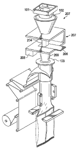
filled in a vertical form, fill, and seal machine. Figure 1 depicts a portion
of a
traditional vertical form, fill, and seal machine. First, product is weighed
and
measured in a weigher 101. The weighers 101 collect and discharge a specified
charge of product. Each charge represents the amount of product which will
occupy a
single bag. Downstream from the weigher 101 is typically a funnel 102 or a
series of
funnels which directs the product. As used herein, "downstream" and "upstream"
refer to relative points or locations in the process or apparatus. Thus, an
event taking
place downstream occurs later in the process and follows events which took
place
upstream. Downstream from the funnel 102 is a product delivery cylinder 103.
As
used in a vertical form, fill, and seal machine, the product delivery cylinder
103 is
often referred to as a former. The packaging film for the final package is
wrapped
1
CA 02899729 2015-08-06
WO 2014/124383
PCT/US2014/015608
around the product delivery cylinder 103 to form a tube. Once the lower
portion of
the tube is sealed, product is delivered through the product delivery cylinder
103 and
into the sealed tube. Thereafter, the top portion of the tube is sealed, cut
and
separated from the upstream film, and a package is formed. The apparatus is a
very
effective bagmaker and can produce bag rates as high as 100 bags per minute.
[0004] During shipping and handling the product within the package begins
to settle, increasing the void space at the top of the package. A package
which has sat
on a retail shelf, after transportation and handling, will often look less
full than a
package taken directly from the bagmaker. This results in a variety of
problems.
First, a package appearing and feeling less full is less appealing to a
customer
compared to a fuller package. Second, many consumers are unpleased to open a
package to realize the package is about half full. Third, due to the increased
void
space after the product settles, the prior art package is larger than needed
at this point
relative to its contents. Such a package unnecessarily takes up valuable space
on a
retail shelf space, in shipping trucks, in warehouses, and in consumers'
pantries.
Further, manufacturing materials such as plastic films are wasted in forming
such a
package.
[0005] For the above reasons, attempts have been made to decrease the void
space in a package. One attempt disclosed in commonly owned U.S. Publication
No.
2006/0165859 which teaches that randomly shaped product tends to settle less
over
time than uniformly shaped product and thus discloses producing randomly
shaped
product. One drawback of this method, however, is that is it not always
desirable to
produce randomly shaped products.
[0006] Another known method is partially filling the package with product,
vibrating the package to settle the product within the package. Thereafter
additional
2
CA 02899729 2015-08-06
WO 2014/124383
PCT/US2014/015608
product is added to the package and the process repeated. Unfortunately, this
process
is very slow and cannot be conducted at high rates on a traditional vertical
form, fill,
and seal machine.
[0007] Accordingly, one object of the instant invention is to provide an
apparatus and method which results in increased compaction of product within a
package. Furthermore, because many packages involve a vertical form, fill, and
seal
machine, it is desirable that the apparatus and method be easily adapted for
use on
such a machine, preferably with only minor modification and without
significantly
decreasing bag rates.
3
CA 02899729 2015-08-06
WO 2014/124383
PCT/US2014/015608
BRIEF DESCRIPTION OF THE DRAWINGS
[0008] The novel features believed characteristic of the invention are set
forth in the appended claims. The invention itself, however, as well as a
preferred
mode of use, further objectives and advantages thereof, will be best
understood by
reference to the following detailed description of illustrative embodiments
when read
in conjunction with the accompanying drawings, wherein:
[0009] Figure 1 is a perspective view of a prior art filling apparatus;
[0010] Figure 2 is a perspective view of a filling apparatus employing one
embodiment of the invention comprising a settling chamber;
[0011] Figure 3 is a top profile view of a rotary settling device comprising
multiple settling chambers in their discharging and receiving positions;
[0012] Figure 4 is a perspective view of a rotary settling device comprising
multiple settling chambers in a mid-rotation position;
[0013] Figure 5 is a perspective view of a filling apparatus employing one
embodiment of the invention comprising a settling chamber and multiple
bagmaker;
and
[0014] Figure 6 is a top profile view of a rotary settling device comprising
multiple settling chambers in their discharging and receiving positions.
4
CA 02899729 2015-08-06
WO 2014/124383
PCT/US2014/015608
DETAILED DESCRIPTION
[0015] Several embodiments of Applicants' invention will now be described
with reference to the drawings. Unless otherwise noted, like elements will be
identified by identical numbers throughout all figures.
[0016] Generally, this invention relates to a method and apparatus for
compacting a slug of product and increasing compaction of product within a
package.
Compaction refers to the density of product within a package. A goal is to
form and
compact an intermediate slug of product which is subsequently discharged into
a
packaging apparatus and eventually into a package. An additional goal in one
embodiment is to ensure the increased compaction remains throughout the
packaging
operation. Applicants have found forming and compacting an intermediate slug
and
then discharging said slug for packaging results in increased product
compaction. A
slug of product refers to a collected charge of product.
[0017] Because of the resulting increased compaction of the product at the
bagmaker, less settling occurs during the subsequent, shipping, handling, and
displaying of the package. Thus, the apparatus and method of this invention
ensures
that the package displayed on the shelf will more resemble the package as seen
at the
bagmaker. As used herein, a bagmaker refers to any packaging apparatus. The
method and apparatus can be utilized on a wide variety of bagmakers including
but
not limited to a vertical form, fill, and seal machine and horizontal form,
fill, and seal
machines, bag in a box apparatus, as well as boxing machines. Likewise, a
packaging
apparatus referred to as a fill seal bagmaker, whereby premade bags are
opened,
filled, and sealed, can also be utilized. The final packages described herein
can
comprise traditional flex packages associated with snack product, vertical
packages,
CA 02899729 2015-08-06
WO 2014/124383
PCT/US2014/015608
box packaging, bag in a box packaging, and other products containing product
which
is subject to settling.
[0018] The apparatus and method can be utilized to increase compaction of
a variety of products including food products such as chips, pretzels,
cookies, noodles,
nuts, cereal, and seeds. Likewise, this invention also applies to individually
wrapped
products such as individually wrapped mints or other candies which are
susceptible to
settling. The apparatus and method also works for other various dry products
including dog food, cat food, etc.
[0019] Figure 2 is a perspective view of a filling apparatus employing one
embodiment of the invention comprising a settling chamber. In Figure 2, a
settling
device 207 is located between the weigher 101 and the product delivery
cylinder 103
of a vertical form, fill, and seal machine. The weigher 101 can comprise
virtually any
weigher known in the art. In one embodiment, the weigher 101 is a statistical
weigher. As depicted, downstream of the weigher 101 is a receiving funnel 102.
A
receiving funnel 102, or a series of funnels, receives and guides product to
the
downstream bagmaker. As used herein a receiving funnel 102 refers to any
device
downstream of a weigher but upstream from a settling device which collects and
directs product. The receiving funnel 102 can be attached and part of the
weigher 101
and can comprise vertical or slanted walls. In one embodiment, there is a
metal
detector located between the weigher 101 and the receiving funnel 102 to
monitor
foreign debris. Those skilled in the art will appreciate that a receiving
funnel 102 is
not necessary in all embodiments. Downstream of the receiving funnel 102 and
the
weigher 101 is the settling device 207.
[0020] As depicted the settling device 207 comprises a single settling
chamber 204, a vibrator 208, and a gate 206. A settling device, as used
herein, refers
6
CA 02899729 2015-08-06
WO 2014/124383
PCT/US2014/015608
to a device which receives and captures an amount of product in order to form
an
intermediate slug of compacted product. A settling chamber 204 is a distinct
chamber
which receives and retains product. In one embodiment the settling chamber 204
has
four vertical walls and an open top and bottom.
[0021] Applicants have found that collecting product discharged from the
weigher 101 and holding product, for a period of time, in the settling chamber
204
facilitates settling of the product and increases compaction of the product.
Increasing
the settling of the product during packaging results in a decrease of post
manufacturing settling. The settling chamber 204 can be jostled or vibrated
via a
vibrator 208 to facilitate and speed up the settling of the product. The time
necessary
and the amount of external energy, such as vibrations, required to facilitate
settling is
dependent upon many factors including but not limited to the geometry of the
product,
the size and geometry of the settling chamber, the size of the slug, and the
level of
compaction desired. Those skilled in the art will be able to determine the
amount of
time and energy required to yield a desired level of compaction. Other
movements
such as vertical, horizontal, rotational, vibrational, and mixtures thereof
can also be
imparted to the settling chamber to facilitate settling of the product which
results in
increased compaction. The vibrator 208, which is optional, can comprise any
device
which vibrates the settling chamber 204. The vibrator 208 can be located in
various
places throughout the settling device 207.
[0022] Applicants have found that the geometry of the settling chamber 204
has an effect on the shape of the packaged slug as well as the shape of the
final
package, especially if the final package is a traditional flex bag. In one
embodiment
the cross-sectional shape of the settling chamber 204 is substantially similar
to the
desired shape of the slug. For example, in one embodiment the settling chamber
204
7
CA 02899729 2015-08-06
WO 2014/124383
PCT/US2014/015608
has a substantially oval cross-section to mimic the substantially oval cross-
section of a
traditional flex bag. Other cross-sections may be utilized including but not
limited to
a circular and square cross-section.
[0023] The height of the settling chamber 204 can be varied according to the
desired size and shape of the intermediate slug which ultimately dictates the
size and
shape of the finished product. In one embodiment the size of the settling
chamber 204
is approximately 0.5 to 2.5 times the height of the final package, and in one
embodiment the settling chamber 204 is approximately 1.25 times the height of
the
final package. The size of the chamber is dependent upon a variety of factors
including the amount of settling required. In one embodiment, the height of
the
settling chamber 204 is chosen so as to properly fit between the weigher and
the
packing apparatus without raising the weigher.
[0024] In one embodiment, the bottom of the settling chamber 201 has a
larger opening than the top of the settling chamber. For some products
susceptible to
bridging, having a larger exit diameter minimizes bridging. This helps the
product
maintain its desired compact shape and results in faster and more efficient
discharges.
[0025] At the bottom of the settling chamber 204 is a gate 206. The gate
206 can comprise many types of gates including sliding and swinging gates. In
one
embodiment the gate 206 is a sliding gate which allows for quick and efficient
discharge of the product from the settling chamber 204.
[0026] Downstream of the gate 206 is the product delivery cylinder 103. In
some embodiments there is an intermediate funnel 209 which directs product
discharged from the gate 206 to the product delivery cylinder 103. The
intermediate
funnel 209 can comprise one or more funnels which can comprise straight or
slanted
walls. Further, the intermediate funnel 209 can comprise a variety of shapes.
In one
8
CA 02899729 2015-08-06
WO 2014/124383
PCT/US2014/015608
embodiment, the intermediate funnel 209 has a shape similar to the shape of
the
settling chamber 204.
[0027] In some embodiments, as the process moves downstream from the
receiving funnel 102 to the product delivery cylinder 103, each subsequent
downstream transition point has a larger diameter than the upstream transition
point.
Thus, in such an embodiment, the intermediate funnel 209 has a larger diameter
than
the settling chamber 204 but a smaller diameter than the product delivery
cylinder
103. Such an arrangement minimizes bridging and any other disruption to the
united
slug.
[0028] Thus, the method for compacting a slug of product begins by
weighing an amount of product in a weigher. Then, the product is directed and
received into a settling device. Once the product is in the settling device,
the product
is compacted to form a slug of product. As discussed, this can be accomplished
by
storing the product for a time, or by jostling, rotating, and/or vibrating the
settling
device. After compacting the product, the product is discharged to a product
delivery
cylinder. It should be noted that the product can be directly discharged into
the
product delivery cylinder or it can be discharged into an intermediate funnel
or chute
before reaching the product delivery cylinder. Thereafter the slug is
deposited from
the product delivery cylinder into a package. As discussed above, the settling
device
is located downstream from a weigher and upstream from the product delivery
cylinder. Further, the settling device can comprise only a single settling
chamber, or
the device can comprise more than one settling chamber.
[0029] In one embodiment the settling device 207 comprises only a single
settling chamber 204. However, in other embodiments the settling device 207
comprises more than one settling chamber 204. In one embodiment, two or more
9
CA 02899729 2015-08-06
WO 2014/124383
PCT/US2014/015608
settling chambers 204 act in parallel, each discharging its slug to the
downstream
product delivery cylinder 103. In other embodiments at least two chambers 204
act in
series whereby a first chamber is located below a second chamber and product
is
partially settled in a first chamber before being deposited for further
settling in a
second chamber. In one embodiment, one or more settling chambers 204 are
located
on a rotary settling device. In one embodiment each subsequent chamber results
in
increased settling.
[0030] Figure 3 is a top profile view of a rotary settling device comprising
multiple settling chambers in their discharging and receiving positions. A
rotary
settling device 304 is a device comprising more than one settling chamber
whereby
the settling chambers are axially rotatable within the settling device. Figure
3
illustrates a rotary settling device 304 comprising eight settling chambers
204a-h
located above the stationary turret table 305, a gate 306, and a vibrator 208.
While
the figure illustrates eight settling chambers 204a-h, other numbers of
settling
chambers may also be utilized. Those skilled in the art will understand that
the
number of required settling chambers is dependent upon a variety of factors
including
but not limited to the geometry of the product, the desired size and weight of
each
slug, and the desired throughput in bags per minute, amount of settling time
required,
etc.
[0031] In a rotary settling device 304, the settling chambers 204a-h can be
arranged in a variety of positions. In one embodiment, the centers of each
settling
chamber are evenly spaced along the turret table 305. In one embodiment the
chambers are evenly spaced and oriented like a wagon spoke. As depicted, the
settling chambers 204 are angled relative to the turret table 305 to maximize
the
number of chambers which will fit on the turret table 305.
CA 02899729 2015-08-06
WO 2014/124383
PCT/US2014/015608
[0032] In the embodiment depicted, the settling chambers 204 have an open
top and bottom so the product is maintained within the settling chambers 204
by the
presence of the stationary turret table 305. In such an embodiment the
settling
chambers 204 glide and rotate over the turret table 305. There is an opening
308 in
the turret table 305 located above the gate 306. In one embodiment, the shape
of the
opening corresponds to the shape of the settling chamber 204. The chamber
located
in the position above the gate 306, and aligned with the opening 308, is
referred to as
the discharge chamber 204a. The product in the discharge chamber 204a is
maintained by the gate 306. Accordingly, when the gate 306 is opened, via
sliding or
otherwise, the product falls through the opening 308 in the turret table 305
and passes
the open gate 306. Those skilled in the art will understand that there are
other ways of
maintaining product within each settling chamber such as having a separate
gate for
each settling chamber.
[0033] In one embodiment, downstream and below the gate 306 is the
product delivery cylinder 103. In such an embodiment, the compacted slug is
discharged from the discharge chamber and into the product delivery cylinder
103
where it is subsequently packaged in a bagmaker.
[0034] The settling chambers 204 can be filled in a variety of locations. In
one embodiment, the discharge chamber 204a is also the same settling chamber
which
receives product, called the receiving chamber. In such an embodiment, after
discharging product in the discharge chamber 204a the gate 306 will close.
Thereafter, the discharge chamber 204a will then receive product. All of the
settling
chambers 204 in turn will then move one spot in the progression, during which
time
the product in the settling chamber settles and becomes more compact. Thus, in
some
embodiments the receiving and discharging do not take place simultaneously.
11
CA 02899729 2015-08-06
WO 2014/124383
PCT/US2014/015608
[0035] Figures 3 and 4, however, depict an embodiment in which the
receiving and discharging does not take place in the same chamber. As depicted
in
figure 3, the discharging chamber 204a discharges product and a different
chamber,
the receiving chamber 204c receives product from the receiving funnel 102. In
one
embodiment, the discharging and the receiving takes place simultaneously.
Thus,
after the discharge chamber 204a discharges its product, it rotates two
positions to
become the receiving chamber 204c at which time it receives product. In other
embodiments the discharge chamber 204a will only rotate one spot before
becoming
the receiving chamber whereas in other embodiments the discharge chamber will
rotate multiple positions before becoming the receiving chamber. The location
of the
receiving and discharging positions depends on a variety of factors including
but not
limited to the location of the receiving funnel 102 and the product delivery
cylinder
103 and the required amount of settling.
[0036] After the receiving chamber 204c has received its product, it rotates
clockwise throughout the positions until it again becomes the discharge
chamber
204a. While the example has been described as rotating clockwise, this should
not be
deemed limiting as the device can also rotate counterclockwise.
[0037] While the settling chambers 204 are rotating, the product becomes
more compact. In one embodiment, a vibrator 208 vibrates the product within
the
settling chambers 204 to facilitate settling of the product. The vibrator 208
can be
placed on a variety of places, including but not limited to, on the stationary
turret
table 305, attached to the chambers 204, or otherwise attached to the rotary
settling
device 304 or other supporting structure.
[0038] As shown in figures 3 and 4, the receiving funnel 102 is located atop
the rotary settling device 304. The receiving funnel 102 directs product to
the
12
CA 02899729 2015-08-06
WO 2014/124383
PCT/US2014/015608
receiving chamber. As noted above, the receiving funnel 102 may be directly
below
the weigher 101 or it may be below another funnel or series of funnels.
[0039] Figure 4 is a perspective view of a rotary settling device comprising
multiple settling chambers in a mid-rotation position. Figure 4 also
illustrates the
opening 308 located on the stationary table 305. As depicted, the chambers are
in
mid-rotation so the chambers are not receiving or discharging product. In
other
embodiments, however, product is received and/or discharged during rotation.
In
some embodiments, however, it is desired that the compact slug is maintained
in its
compact state after the slug has been formed.
[0040] In Figure 4, a stationary top 409 is depicted. The top 409 acts to
ensure that the product within the settling chambers 204 does not escape the
settling
chambers 204. Further, the top 409 acts to keep external items from entering
the
settling device and subsequently becoming packaged. The top 409 is not
necessary in
all embodiments, and those skilled in the art will understand which processing
conditions will warrant such a top.
[0041] As depicted, the intermediate funnel 209 and the product receiving
cylinder 103 are depicted downstream of the opening 308. In Figure 4, the
product
receiving cylinder 103 is part of the bag former in a vertical form, fill, and
seal,
machine. In one embodiment, the product receiving cylinder 103 is directly
connected to the rotary device 304. In other embodiments the product receiving
cylinder 103 is not directly attached to the rotary device 304. The product
receiving
cylinder 103 may be separated from the rotary device 304 by a gap or it may be
connected via other equipment such as the intermediate funnel 209.
[0042] In one embodiment, the product in the package comprises product
from only a single settling chamber. In such an embodiment, the amount of
product
13
CA 02899729 2015-08-06
WO 2014/124383
PCT/US2014/015608
received in the receiving chamber is equal to the amount of product in the
final
package.
[0043] In still other embodiments, the final package comprises two slugs of
product. In one embodiment the package comprises product from at least two
different settling chambers. In other embodiments the package comprises two
slugs
of product from the same chamber. In such an embodiment a first slug is first
formed
and discharged and then subsequently a second slug is formed in the same
chamber
and then discharged.
[0044] Applicants have found that in some products the compaction is
further increased when two or more smaller slugs are compacted separately and
then
added into a single package. For example, if the final product is to comprise
two
slugs of product, then the slugs formed from two different chambers will both
be
deposited to a single package. Referring back to Figure 3, in such an
embodiment a
single package will comprise product discharged from the discharge chamber
204a as
well as product from the chamber 204h located one spot behind the discharge
chamber 204a. Thus, product from both chambers 204a/204h is deposited to a
vertical form, fill, and seal machine to be packaged in a single package.
[0045] In one embodiment, the height of each chamber is selected so that
existing apparatuses can be retrofitted with charge compaction without, for
example,
raising the weigher. As an example, in one embodiment, due to the multi-charge
method, the settling chambers can be made shorter in height, due to the height
being
spread amongst multiple chambers, and as a result the weigher does not have to
be
moved. This results in decreased capital costs to retrofit an existing
apparatus.
[0046] Applicants have found that after inducing settling the slug maintains
its shape and compaction as it is packaged. This results in less settling
after
14
CA 02899729 2015-08-06
WO 2014/124383
PCT/US2014/015608
packaging giving the consumer a fuller package which more resembles the fuller
look
of a bag at the bagmaker. As previously discussed, increasing settling during
packaging reduces post package settling which results in several benefits. One
such
benefit is the ability to use a comparatively smaller package for the same
product
weight. This results in decreased production costs as less material is
required to
manufacture the package. Additionally this results in decreased shipping costs
as
more packages can fit in a given volume. Further, this allows more packages to
be
displayed on the retail shelf as smaller packages occupy less space. Likewise,
a
smaller package allows a consumer to store the same amount of product in a
smaller
space, thus freeing valuable pantry space.
[0047] As discussed, this apparatus and method provide the opportunity to
package the same quantity of product in a comparatively smaller package. The
smaller package can have a decreased height, width, or combinations thereof
compared to the previous package. In one embodiment the width of the package
is
not altered and only the height dimension is changed. Such an embodiment
minimizes the modifications required to the bagmaker.
[0048] The following examples demonstrate the effectiveness of one
embodiment of the instant invention and are for illustrative purposes only.
Accordingly, the following examples should not be deemed limiting.
Control
[0049] A trial was conducted using chips with a product weight of 21.5
ounces. The wheat chips were thin wafers having ridges. A settling device was
not
used on the control. The bags had a width of 12 inches, a total height of
18.75 inches
and a usable height of 17.75 inches after deducting one inch for the top and
bottom
seals. The void space in each package was measured and the fullness level of
each
CA 02899729 2015-08-06
WO 2014/124383
PCT/US2014/015608
bag calculated. The void space was measured by measuring the average level of
product in the package. The packages removed from the bagmaker, which was a
vertical form, fill, and seal machine, were approximately 86% full on average
and had
an average product level of 15.25 inches. Thereafter to determine the
conditions of
the packages after sitting on the shelf, the packages were subjected to a
simulated
retail process which included simulating the transporting, handling, and shelf
time of
a typical package. After simulation, the void space was measured and the
fullness of
each bag was calculated to be approximately 78% on average with a product
level of
13.85 inches. Thus, the fullness of the packages decreased by about 8% on
average
after the shelf simulation, and the product level decreased by an average of
1.4 inches.
Single Charge
[0050] In the next trial, a non-rotary settling apparatus comprising a single
settling chamber, similar to that of Figure 2 in operation, was utilized using
the single
charge method whereby each package comprised a single slug of product. The
settling device had settling chambers comprising a substantially oval cross
section and
a width of 12 inches. Because of the settling of the product, a smaller bag
was
utilized. The smaller bag had a width of 12 inches and a height of 16.75
inches with
about 15.75 inches of useable space. At the bagmaker the packages were
approximately 86% full and had a product level of about 13.55 inches. Thus,
the
settling device decreased the same quantity of product in a bag with the same
width
from a product level of 15.25 inches to a product level of 13.55 inches at the
bagmaker. After the shelf simulation, the packages were approximately 82% full
and
had a product level of about 12.85 inches. Thus, the fullness of the package
decreased
by only about 4% and resulted in a fuller bag compared to the control.
Further, the
16
CA 02899729 2015-08-06
WO 2014/124383
PCT/US2014/015608
product level dropped only about 0.7 inches which is about half of the drop
experienced in the control.
Multi-Charge
[0051] In the next trial, the same apparatus was utilized using the multi-
charge method wherein the final package comprised two slugs of product. Thus,
in
this embodiment, the settling chamber formed and discharged a slug, and then
the
same settling chamber subsequently formed and discharged a second slug into
the
same package as the first discharged slug. The same size bag as the single
charge was
also used in the multi-charge trial. At the bagmaker the packages were
approximately
87% full and had product levels of about 13.65 inches. After the shelf
simulation, the
packages were approximately 83% full and had a product level of about 13.15
inches.
Thus, compared to the single-charge method, the multi-charge method resulted
in a
fuller bag both at the bagmaker and after shelf-simulations.
[0052] In both the single-charge and the double-charge, a smaller package
was produced which held the same quantity of product as the larger bag in the
control,
but which required less material to manufacture. Accordingly, compacting the
product results in decreased manufacturing costs, decreased shipping costs, an
increased number of packages available for a given amount of retail space, a
package
which required less pantry space, and a package which appeared fuller to the
retail
consumer.
[0053] In one embodiment, charge compaction is combined with a multiple
bagmaker to significantly increase the packaging speed and efficiency. Any
multiple
bagmaker known in the art can be used, and Applicants will describe the
invention in
relation to a duplex vertical form, fill and seal machine. Those skilled in
the art will
17
CA 02899729 2015-08-06
WO 2014/124383
PCT/US2014/015608
understand that the number of bags the multiple bagmaker produces at one time
will
dictate the necessary modifications to the weigher and charge compaction
device.
[0054] Figure 5 is a perspective view of an apparatus with a multiple
bagmaker incorporating charge compaction in accordance with one embodiment of
the invention. In Figure 5, a duplex vertical form, fill and seal machine with
delivery
cylinders 103 and 113 is utilized. The weigher 101 is split into two sections
with each
half weighing and discharging a slug of product into its corresponding half of
the
receiving funnel 102 which guides the product into the settling device 207. As
depicted, the settling device 207 comprises two settling chambers 204, 214,
each for a
slug of product, a vibrator 208, and a gate 206. The product is discharged
from the
settling chambers 204, 214 through the gate 206 to the product delivery
cylinders 103
and 113, respectively. While the example has been described as using a duplex
vertical form, fill and seal machine, this should not be deemed limiting as
the device
can be adapted for any number of bagmakers.
[0055] The method for compacting and packaging a plurality of slugs of
product simultaneously is substantially similar to that described above in
relation to a
single slug of product. A plurality of slugs of product is weighed in a split
weigher.
The number of sections into which the weigher is split is determined by the
number of
product delivery cylinders of the multiple bagmaker. Thus, for a duplex
bagmaker the
weigher is split into two sections, three sections for a triplex bagmaker and
so on.
The slugs of product are then directed from the weigher and received into a
settling
device. Once the slugs of product are in the settling device, the slugs are
compacted
to form compacted slugs of product. After compacting, the slugs are discharged
to a
number of product delivery cylinders. Thereafter the slugs are deposited from
the
product delivery cylinders into a corresponding number of packages.
18
CA 02899729 2016-01-08
[0056] In one embodiment, the settling device 207 comprises only the
settling chambers 204, 214 for each slug of product to be packaged. In other
embodiments, the settling device 207 comprises multiple settling chambers 204,
214
that act in parallel, each discharging its slug of product to the downstream
product
delivery cylinders 103, 113. Figure 6 is a top profile view of a rotary
settling device
comprising multiple settling chambers in their discharging and receiving
positions.
The rotary settling device 304 shown in Figure 6 comprises twelve settling
chambers
204a-f, 214a-f located above the stationary turret table 305, a gate 306, and
a vibrator
208. Those skilled in the art will understand that the number of settling
chambers in a
single position is dependent upon the number of product delivery cylinders of
the
multiple bagmaker and the settling chambers grouped at a position rotate
together
such that they receive and discharge product simultaneously. Thus, if a
triplex
bagmaker were being used, there would be a third settling chamber (not shown)
at
each position a-f. The multiple-chamber rotary settling device operates as
described
above in reference to compacting and packaging a single slug of product.
[0057] The scope of the claims should not be limited by the preferred
embodiments set forth in the examples, but should be given the broadest
purposive
construction consistent with the description as a whole.
19
CA 02899729 2015-08-06
WO 2014/124383
PCT/US2014/015608
ADDITIONAL DESCRIPTION
[0058] The following clauses are offered as further description of the
disclosed invention.
1. An apparatus for compacting and packaging a plurality of product slugs
simultaneously, said apparatus comprising:
a multiple bagmaker, said bagmaker having a number of product
delivery cylinders;
a weigher; and
a settling device;
wherein said settling device is located between said weigher and said product
delivery cylinder.
2. The apparatus according to any preceding clause wherein said weigher is
divided into a number of sections equal to said number of product delivery
cylinders.
3. The apparatus according to any preceding clause wherein said multiple
bagmaker comprises a duplex vertical form, fill, and seal machine.
4. The apparatus according to any preceding clause wherein said settling
device
comprises at least two settling chambers.
5. The apparatus of claim 4 wherein said settling chambers comprise a cross-
sectional shape substantially similar to the desired shape of the product
slug.
CA 02899729 2015-08-06
WO 2014/124383
PCT/US2014/015608
6. The apparatus according to any preceding clause wherein said settling
chambers comprise a substantially oval cross-section.
7. The apparatus according to any preceding clause wherein said settling
chambers comprise a top end and a bottom end, and wherein said bottom end
comprises a larger opening than said top end.
8. The apparatus according to any preceding clause wherein said settling
device
further comprises a gate.
9. The apparatus according to any preceding clause wherein said settling
devices
comprise at least four settling chambers and at least one gate, wherein said
settling chambers are axially rotatable within the settling device, and
wherein
a number of said settling chambers equal to said number of said product
delivery cylinders are grouped at a single position.
10. The apparatus according to any preceding clause further comprising a
stationary turret table, wherein said stationary turret table is located below
said
settling chambers.
11. The apparatus according to any preceding clause 10 wherein said
stationary
turret table comprises an opening located above said gate.
12. The apparatus according to any preceding clause further comprising a
stationary table located above said at least four rotating settling chambers.
21
CA 02899729 2015-08-06
WO 2014/124383
PCT/US2014/015608
13. The apparatus according to any preceding clause further comprising at
least
one funnel located above said at least two rotating settling chambers.
14. The apparatus according to any preceding clause wherein said settling
device
further comprises a vibrator.
15. A method for compacting and packaging a plurality of product slugs with
an
apparatus comprising a multiple bagmaker having a number of product
delivery cylinders, said method comprising:
a) weighing a plurality of product slugs in a weigher, wherein said
weigher is divided into a number of sections equal to said number of product
delivery cylinders;
b) receiving said plurality of product slugs to a settling device;
c) compacting said plurality of product slugs in said settling device to
form compact slugs of product;
d) discharging said compact slugs of product to said number of product
delivery cylinders, wherein each compact slug of product is discharged into a
separate product delivery cylinder; and
e) depositing said slugs of product from said product delivery cylinders
to packages,
wherein said settling device is located downstream from said weigher and
upstream from said product delivery cylinder.
22
CA 02899729 2015-08-06
WO 2014/124383
PCT/US2014/015608
16. The method according to any preceding clause wherein said receiving
step
comprises receiving product into at least four settling chambers, wherein a
number of said settling chambers equal to said number of said product
delivery cylinders are grouped together.
17. The method according to any preceding clause wherein said compacting
step
comprises rotating said product in four settling chambers, wherein said
settling
chambers are axially rotatable within the settling device.
18. The method according to any preceding clause wherein said compacting
step
comprises vibrating said settling device.
19. The method according to any preceding clause wherein said depositing
step
comprises depositing said slugs into a duplex vertical form, fill, and seal
machine.
20. The method according to any preceding clause wherein said receiving
step and
said discharging step occur simultaneously.
21. The method according to any preceding clause wherein said receiving
step
comprises receiving product into at least one settling chamber, and wherein
said depositing step comprises depositing at least two slugs from at least one
settling chambers into a package.
23