Note: Descriptions are shown in the official language in which they were submitted.
CA 02899934 2015-07-30
WO 2014/124297 PCT/US2014/015364
APPLICATOR
FIELD OF THE INVENTION
The present invention is directed to an applicator for topically applying a
composition to a
face.
BACKGROUND OF THE INVENTION
Typical applicators for topically applying facial skin care compositions
(e.g., foundations)
to skin and facial hair that are made of expanded foam do not provide a smooth
and continuous
deposition of the composition on a face for the purposes of concealing facial
skin imperfections
and tine facial hair (e.g., vellus hair). These existing applicators typically
have a rough, and
often porous and absorbent surface, which do not allow for an even and smooth
deposition.
There is a need to maximize the effectiveness of these skin compositions
(e.g., concealing
benefits) with even and smooth facial deposition.
Another shortcoming of these applicators is they do not offer the ability to
manage a
reservoir of skin care composition between the applicator surface and facial
substrate and yet
provide the desired even and smooth deposition. There is also a need for an
applicator to be
made from a material that resists absorption of the skin care composition
during contact.
There is yet a further need for the applicator to be adaptable for use to the
diverse
contours of a human face (e.g., broad areas as cheeks as well as challenging
areas around the
nose and eyes) and also intuitive to the user in how to hold and use the
applicator. There is a
need for the applicator to be sanitary, i.e. allow the applicator to be washed
after one or more
uses. There is also a need for applicator to be able to hold a reservoir of
dispensed skin care
compositions in the dosing area and keep it from running before being applied
to the face.
SUMMARY OF THE INVENTION
The present invention is directed to solving one or more of these problems.
Without
wishing to be bound by theory, the present invention identifies the materials,
geometry, and
methodology to address one or more of the problems.
Firstly, the inventive applicator helps to addresses the need of managing and
concealing
fine facial hair of a human female. Depending on the individual and exactly
where on the face
this hair is located, the hair may be vellus hair with shaft diameters ranging
from I to 30 micro
meters to darker terminal hair with shaft diameters typically larger than 30
micrometer to about
120 micrometers. Without wishing to be bound by theory, concealing this hair
is best achieved
CA 02899934 2015-07-30
WO 2014/124297 PCT/US2014/015364
2
by using the applicator of the present invention to smoothly and evenly
applying a skin care
composition to skin and hair, and concurrently laying down (i.e., flatten) the
hair against the skin.
Furthermore, results are maximized by stroking the applicator along the grain
of the hair.
Results may also be maximized by including chemistry in the skin care
composition to further
minimize the appearance the fine facial hair through opacity and maintaining
the adhesion of hair
to the skin.
Accordingly, one aspect of the invention provides an applicator, configured
for topically
applying a composition to a face, which comprises a first surface and an
opposing second
surface, wherein the second surface is a concave surface and the second
surface comprises a non-
absorbing elastomeric material.
A second aspect provides for a method of provide hair minimization to a face
comprising
the step of topically applying a film-forming composition to the face by the
aforementioned
applicator. A third aspect of the invention provides for a kit comprising the
aforementioned
applicator; and a container containing a skin care composition; and optionally
use instructions.
Manufacturing methods are also provided.
BRIEF DESCRIPTION OF THE DRAWINGS
Figure 1 is a perspective of an applicator of the present invention.
Figure 2 is a top view of the applicator of figure I.
Figure 3 is a bottom view of the applicator of figure 1.
Figure 4 is cross sectional front view of the applicator of figure 1.
Figure 5 is a cross sectional right view of the applicator of figure I.
Figure 6 is an exploded view of a cross sectional portion of figure 5.
Figure 7 is an example of kit that has the applicator of figure I and a
secondary package
that is capable &containing the applicator and a facial foundation
composition.
Figure 8a is a user topically using the applicator of figure l on her nose.
Figure 8b is the user grabbing the applicator in a first position before using
the applicator
as shown in figure 8a.
Figure 9a is a user topically using the applicator of figure I on her nose.
Figure 9b is the user grabbing the applicator in a second position before
using the
applicator as shown in figure 9a.
Figure 10a is a user topically using the applicator of figure I on her cheek.
CA 02899934 2015-07-30
WO 2014/124297 PCT/US2014/015364
3
Figure 10b is the user grabbing the applicator in a third position before
using the
applicator as show in figure 10a.
Figure I I a is a user topically using the applicator of figure 1 on her
cheek.
Figure 1 I b is showing the user grabbing the applicator in a fourth position
before using
the applicator as shown in figure t Ia.
Figure 12 is a deposition grading scale for even deposition of a formulation
from an
applicator.
DETAILED DESCRIPTION OF THE INVENTION
Composition of Applicator
One aspect of the invention provides for an applicator wherein a surface of
the applicator
comprises of a non-absorbing elastomeric material, preferably wherein a first
surface and an
opposing second surface each comprise a non-absorbing elastomeric material.
In one
embodiment, the surface of the applicator configured to make contact with a
facial substrate at
least comprises the non-absorbing elastomeric material, wherein preferably the
surface is also a
concave surface. Without wishing to be bound by theory, absorbing materials,
such as sponges,
exhibit inany undesirable characteristics for hair lay-down applications.
Based on unpublished
consumer research, some consumers feel that a portion of the skin care
composition is being lost
by being absorbed into the sponge and therefore not being completely dosed on
to the skin.
Another challenge with absorbing materials is their use may lead to unsanitary
conditions since
sponges and other such materials are challenging to clean or wash and can
harbor bacteria. Also,
absorbing materials do not provide even applications of skin care composition
on to the facial
substrate given the rough or rion-smooth topical surface that absorptive
materials typically have.
In one einbodiment, at least 10%, or 15%, 25%, 30%, 40%, 50%, 60%, 70%, 80%,
90%,
95%, or 98%, or more of an outer surface area of the applicator comprises a
non-absorbing
elastomeric surface. In another embodiment, less than 100%, or 98%, 95%, 90%,
80%, 70%,
60%, 50%, 40%, 30%, 25%, or 15%, or less: but greater than 10%, of the outer
surface area of
the applicator comprises a non-absorbing elastomeric material. In yet another
embodiment, 40%
to HX00, preferably from 50% to 100%, alternatively from 60% to 100%,
alternatively
combinations thereof, of the outer surface area of the application comprises
the non-absorbing
elastomeric material.
In one embodiment, from 5% to 100%, preferably from 10% to 100%, more
preferably
from 50% to 100%, alternatively from 25% to 75%, alternatively from 10% to
90%, alternatively
CA 02899934 2015-07-30
WO 2014/124297 PCT/US2014/015364
4
from 80% to 100%, alternatively combinations thereof, by weight of the
applicator comprises a
non-absorbing elastorneric material. In yet another embodiment, the applicator
comprises 2, 3, 4,
5, or more different types of materials. The different types of materials may
or may not all be
non-absorbing elastomeric materials.
Another aspect of the invention provides for at least a surface of the
applicator configured
to make contact with the skin or facial substrate to be comprised of a non-
absorbing elastomeric
material that is smooth for even application of skin care compositions to the
facial substrate. Yet
another aspect of the invention provides for the material of the applicator,
at least the outer
surface, to be washable to allow the user to clean the applicator between one
or more uses.
In one embodiment, the non-absorbing elastomeric material of the applicator is
a
combination of a hydrogenated styrene butadiene block copolymer and a silicone
fluid,
preferably wherein the silicone fluid is a dimethyl silicone fluid. The
copolymer compound may
be obtained from Kuraray Plastics Co., Ltd (Osaka, Japan); SEPTON COMPOUND
JS2ON.
The dimethyl silicone fluid may be obtained from Momentive Performance
Materials Japan LLC
(Tokyo, Japan); TSF451 Series of products. In another embodiment, the
applicator comprises
from at least 95%, preferably at least 96%, or 97%, 98%, or at least 99% of
the block copolymer
by weight of the applicator. Alternatively the applicator comprises from 90%
to 100%,
alternatively from 99% to 99.9%, alternatively combinations thereof, of the
block copolymer by
weight of the applicator. In another embodiment, the applicator material
further comprises a
silicone fluid, preferably from 0.01% to 2 %, more preferable from 0.1% to
1.5%, alternatively
from 0.5% to 1.2%, alternatively from 0.5% to 1%, alternatively combinations
thereof, of the
silicone fluid by weight of the applicator. In one non-limiting example, the
material of the
applicator comprises 99.3 % of the block copolymer and 0.7% of the silicone
fluid, by weight of
the applicator.
The material(s) comprising the applicator can be injected molded or caste
molded to form
the applicator. Alternatively these materials may be vulcanized, thermoformed,
assembled and
heat welded or welded with adhesives, injection molded, extruded, die cut,
cast, or combinations
thereof.
Non-limiting examples applicator materials that could be used on a surface of
the
applicator, or even throughout the applicator as a whole, include a polymer
containing a
heteroatom. Examples may include polyvinylehloride, polyurethanes, polyamides,
polyesters,
polyacrylates, and poiyearbonates. These materials may be used with a
plasticizer. In addition, a
plurality of these materials may be forrned as separate elements and then
combined into a single
CA 02899934 2015-07-30
WO 2014/124297 PCT/US2014/015364
unit (to ultimately make an applicator of the present invention). In one non-
limiting example, a
variety of materials may be die-cut from sheet stock and then assembled with
heat, or adhesives
to form a single composite applicator that yields the desired properties of
inter cilia surface
profile, hardness, and flexibility.
In one embodiment, the applicator is made of several different types of
materials. The
applicator may be formed of a laminate of materials. In such an embodiment,
one or more outer
surfaces of the applicator may have a non-absorbing elastorneric material,
whereas materials in
the interior of the applicator may include other materials that may include
absorbing or non-
absorbing materials; or elastomeric or non-elastomeiic materials; or
combinations thereof. Such
embodiments could provide the advantages of the present invention and yet
allow for greater
design and manufacturing flexibility. These laminates may be made through
heat welding,
adhesives, or multi sequential step casting or injection inolding processes.
Other non-limiting examples of nonabsorbent materials that could be used
throughout the
applicator as a whole, in combination, and/or on a surface of the applicator
include thermoplastic
elastomers, urethanes, and rubber.
Applicator Dimensions
One aspect of the invention provides the applicator to have an overall surface
area from
25 cm2 to 200 cm2, preferably from 30 cm2 to 100 cm2, preferably from 35 cm2
to 80 cm2,
alternatively from 40 cm2 to 60 cm2. In one embodiment, one surface of the
applicator,
preferably the surface configured to make contact with the skin or facial
substrate, is concave. In
such an embodiment, the concave surface preferably has a surface area from 5
cm to 100 cm2,
preferably from 7 cm2 to 50 cm2, more preferably from 10 cm2 to 30 cm2. During
use, not the
entire one surface of the applicator (configured to make contact with the
skin/facial substrate)
will typically make contact with the skin or facial substrate. The percentage
of the one surface of
the applicator making contact with the skin/facial substrate will depend upon
a number of
variables including the user's preferences, contour of the face being treated,
and amount of
composition being applied (at any given time).
In one embrxlirnent when one surface of the applicator is concave, the concave
surface is
configured to contain a volume from 0.030 ml to 0.500 rnl, alternatively from
0.100 ml to 0.220
ml, alternatively from 0.140 ritl to 0.200 ml, alternatively combinations
thereof.
One suitable way to measure this volume is to place the concave surface of the
applicator
up and determine how much water the concave surface is capable of retaining.
In addition, this
CA 02899934 2015-07-30
WO 2014/124297 PCT/US2014/015364
6
volume may be customized to show the user how much product to dispense during
one
application cycle. By making visually or tactile evidence of steel mold
markings or printed or
decorated areas on the surface or changes in geometry or material thickness
changes, the
applicator design or a portion of the design is used to indicate to the user
exactly how much skin
care composition to dispense.
The size of the applicator can be important. Without wishing to be bound by
theory, the
applicator strikes a balance: in being small enough to provide a relatively
compact design (for
travel etc.) and suitable for use by the typical sized human female fingers
(e.g., about I cm in
diameter); but large enough to facilitate easy application for larger skin
substrate areas (e.g.,
cheeks), and maintain a user gripable surface away from the skirt/facial
contact surface (avoiding
unwanted contact and composition loss).
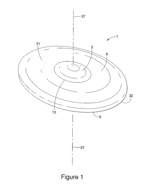
Turning to Figures 1-3, suitable lengths, widths, and thicknesses of the
applicator (1) of
the present invention are described. The length of the applicator (1) is its
longest dimension
when placed along a horizontal plane (35) (e.g., a level table top). A center
vertical axis (37),
orthogonal to the horizontal plane (35), passes through a geometric center
(not shown) of the
applicator (l).
The width of the applicator (1) is measured perpendicular to its length along
the same
horizontal plane (35). The thickest portion of the applicator (1), per the
applicator (1) described
by the figures herein, is at the center vertical axis (37). In one embodiment,
the length of the
applicator is from 45 17181 to 70 mm, preferably from 50 mm to 65 mm,
alternatively from 55 mm
to 60 nun, alternatively combinations thereof. The width of the applicator is
from 30 mm to 60
mm, preferably from 15 mm to 55 men, alternatively from 40 mm to 50 nun,
alternatively
combinations thereof. A thickness of the applicator is from 0.5 mm to 5 mm,
alternatively from
1 mm to 4 men. In one embodiment, the thickness, measured at the center
vertical axis (37), is
from 1 mm to 4 mm, alternatively from 2 mrn to 3.5 mm, alternatively from 3
nun to 4 trim,
alternatively combination thereof. In another embodiment, the thickest portion
of the application
is from 1 mm to 4 mm, alternatively from 2 mm to 3.5 mm, alternatively from 3
rum to 4 mm,
alternatively combination thereof. In one embodiment, the thickness of the
applicator does not
exceed 6 nun, preferably does not exceed 5 mm, alternatively does not exceed 4
mm.
Figure 1 is a perspective view of a non-limiting example of an applicator.
Figure 2 is a
top view of the applicator of figure I, and figure 2 is a bottom view. As
illustrated in these
figures, the applicator (I) may have at least two zones (3, 6) defined by
varying thicknesses. The
outer zone (6) is defined being nearest the outside periphery of the
applicator (1) arid having a
CA 02899934 2015-07-30
WO 2014/124297 PCT/US2014/015364
7
thickness less than inner zone (3). An inner zone (3) includes the center of
the applicator (1).
The circumferential edge (9) and is defined as the outer most peripheral edge
of the applicator
(9), generally defining an elliptical shape. In a preferred embodiment, as
illustrated in the
figures, the outer zone (6) has substantially the same thickness throughout.
The inner zone (3) is
thicker than the outer zone (6). As best illustrated in figures 1 and 2, an
inter-zone border (13)
demarcates the intersection between the outer zone (6) and the inner zone (3)
on the first surface
(31) of the applicator (1). The inter-zone border (13) forms an elliptical
shape (or any other
shape including a curvilinear one) that mimics the elliptical shape (or any
other shape) defined by
the circumferential edge (9)). The inner zone (3) has an ellipsoidal portion
protruding from the
first surface (3 /). The inner zone (3) increases in thickness from the inter-
zone border (13)
toward the center of the applicator (1). In one embodiment, the surface area
of the first surface
(31) of the inner zone (3) is from 1 cm2 to 5 cm2, preferably from 2 cm2 to 4
cm2. The length of
the inner zone (3), along the major axis (not shown), may be from 15 to 25 mm,
preferably from
18 to 22 mm, alternatively combinations thereof. The width of the inner zone
(3), along the
minor axis (not shown), is from 9 mm to 19 mm, alternatively from 11 mm to 17
mm,
alternatively 12 mm to 15 mm, alternatively combinations thereof. in one non-
limiting example,
the length and the width of the inner zone (3) is 20 mrn and 14 mm,
respectively.
In an alternative embodiment, the applicator (1) has an overall oval shape (as
the
curvilinear shape) defined by the circumferential edge (9). Alternatively the
inter-zone border
(13) forms an oval shape. Alternatively the inner zone (3) has an ovoidal
portion protruding
from the first surface (31)
Preferably the outer zone (6) generally has uniform thickness throughout the
outer zone
from 0.5 mm to 3 mm, preferably 1 mm to 2.5 mm, more preferably from 1 mm to 2
mm. In
yet an ever further preferred embodiments, the inner zone (3) has a thickness
from 1.5 mm to 5
min, preferably from 2.5 mm to 4.5 mm, more preferably from 3 mni to 4 min.
The first surface (31) of the applicator (1) opposes the second surface (32).
The second
surface (32) is concave whereas the first surface is generally convex. It is
the second surface
that is configured to primarily make contact with the facial substrate.
Referencing Figure 3, the
second surface (32) of the applicator (1) has at least two relevant radii
(when the applicator (1) is
has an overall elliptical shape). R5 (24), or the fifth radius, is the longest
distance of an axis
between: where the center vertical axis (37) intersects the second surface
(32); and where
circumferential edge (2) intersects the horizontal plane (35). R6 (26), or the
sixth radius, is the
CA 02899934 2015-07-30
WO 2014/124297 PCT/US2014/015364
8
shortest distance of an axis between: where the center vertical axis (37)
intersects the second
surface (32); and where circumferential edge (2) intersects the horizontal
plane (35).
R5 (25) is along the plane of the major axis and R6 (26) is along the plane of
the minor
axis. Accordingly R5 (25) is longer than R6 (26). In one einbcxliment, R5 (25)
is from 19 min to
39 mm, preferably from 24 mm to 34 MITI, alternatively from 26 MITI to 32
irim, alternatively 25
to 30 mm, alternatively from 28 mm to 33 mm, alternatively combinations
thereof. In another
embodiment R6 (26) is from 12 mm to 32 mm, preferably from 17 trim to 27 mrn,
alternatively
from 19 mm to 25 mm, alternatively from 20 rnm to 24 rnm, alternatively
combinations thereof.
In yet another embodiment, the second surface (32) of the applicator is free
or substantially free
of any protrusions or texturing. In a non-limiting example, the R5 (25) and R6
(26) are 28.25
mm and 22 rnm, respectively.
Figure 4 is cross sectional front view of the applicator of figure 1 along the
minor axis.
Figure 5 is a cross sectional right view along the major axis of the
applicator of figure I. The
second surface (32) of the applicator (1) is generally concave.
Accordingly, there is a gap
between the second surface (32) and the horizontal plane (35) when the
applicator (1) is placed
on the horizontal plane (35) without any force being exerted onto the first
surface (31). It is the
second surface (32), along the circumferential edge (9), that makes contact
with the horizontal
plane (35). The maximum gap distance (not shown) is the maximum distance
between the
second surface (32) and the horizontal plane (35). Typically the maximum gap
distance is
measured along the center vertical axis (37). The maximum gap distance is from
1 mm to 5 mm,
preferably from 2 mm to 4 mm. In one non-limiting example the maximum gap
distance is 3
mm, and the thickest portion of the applicator (I) is at the center vertical
axis (37) and is at 3.3
MM.
Figure 4 illustrates: R1, or first radius (21); and R2, or the second radius
(22). These are
not drawn to scale. The circumcenter of RI (21) arid R2 (22) are each located
along the center
vertical axis (37) and the plane of the minor axis of the applicator (1). Rt
(21) is the radius of the
arc of the first surface (31) of the inner zone (3) of the applicator (1)
along the minor axis. R2
(22) is the radius of the arc of the first surface (31) of the outer zone (6)
of the applicator (I)
along the minor axis. In one embodiment, RI (21) is from 9 min to 19 mm,
preferably from 11
mm to 17 nrum more preferably from 12 mm to 16 trim, alternatively
combinations thereof. In
another embodiment, R1 (22) is from 53 mm to 93 mm, preferably from 63 inm to
83 mm,
alternatively from 67 mm to 79 mm, alternatively from 70 mm to 76 mm,
alternatively
combinations thereof.
CA 02899934 2015-07-30
WO 2014/124297 PCT/US2014/015364
9
Figure 5 illustrates: R3, or third radius (23); and R4, or the fourth radius
(24). The
respective circumcenter of R3 (23) and R4 (24) are each located along the
center vertical axis (37)
and the plane of the major axis (not shown) of the applicator (1). R3 (23) is
the radius of the arc
of the first surface of the outerzone (6) of the applicator (1) along the
major axis. R4 (24) is the
radius of the art of the first surface of the inner zone (3) of the applicator
(1) along the major
axis. In one embodiment, R3 (23) is from 21 mm to 33 mm, preferably from 23 mm
to 31 mrn,
alternatively from 25 mm to 29 rnm, alternatively combinations thereof. In
another embodiment,
R4 (24) is from 120 mm to 200 nun, preferably from 130 mm to 190 min,
preferably from 140
mm to 180 nun, alternatively from 150 mm to 166 mm, alternatively from 152 mm
to 164 mm,
alternatively combinations thereof.
Figure 6 is an exploded and cross sectional view of the applicator (1) nearest
the
circumferential edge (9). Figure 6 illustrates R7, or the seventh radius (27).
R7 (27) is the radius
of the arc of the circumferential edge (9) measured from the outer surface
thereof. Preferably R7
is the same circumferentially around the applicator (1). In one embodiment, R7
(27) is 0.01 mm
to 2 mm.
The mass of the applicator is from 1.0 g to 500 g.
Without wishing to be bound by theory, there are potential benefits of having
the inner
zone (3) thicker than the outer zone (6). The larger thickness may provide for
improved mold
processing. Furthermore, the ellipsoidal shaped protrusion (or any other
shaped protrusion) of
inner zone (3) from the first surface (31) of the applicator (1), may help
novice users under the
proper orientation of their fingers for use and perhaps avoiding having their
fingers slip during
use. The protrusion may help in the rigidity of the applicator at its center
to help evenly
distribute downward forces to the circumferential edge (9). The size of the
protrusion may help
visualize for the user how much of the skin care composition should be dosed.
Lastly,
processing may be improved with the protrusion by making applicator easier to
separate should
any co-adhesion happen during bulk packing.
Bending Force:
Another aspect of the invention provides for the applicator to have the right
balance in
bending force. There needs to be enough bending force as to provide hair lay-
down benefits but
not too much so as to provide insufficient flexibility to accommodate the
complex contours of the
human face. Tables 1 a and lb summarizes dimensions of ten applicators (and
standard
deviation). Tables 2a and 2b summarize results from bending force testing from
the applicators
described in Tables I and lb.
CA 02899934 2015-07-30
WO 2014/124297 PCT/US2014/015364
Table la: Dimensions (mrn) Ellipse-Shaped Applicators of Figure 1
Variable: Length Width Thickness2 Height3 __ RA (21)4
Average 57.390 44.165 1,599 6.076 13,824
Standard 0,052. 0,140 0,111 0.266 0.249
Deviation
i.e., the longest dimension.
2 Thickness of the outer zone (6), wherein the thickness of the outer zone (6)
is substantially
uniform throughout the outer zone (6)
3 "Height" is the distance measured along the center vertical axis (35) from
the horizontal plane
(35) to the first surface (31) of the applicator (1), In other words, it is
the maximum gap distance
plus the thick.ness of the inner zone (3) along the center vertical axis C37).
It should be
appreciated, given the properties of the material, the mass of the applicator,
and concave surface
of the applicator facing down, and overall geometry of the application, are
variables that may
impact the "height" dimension herein.
4 Radii RI, R2, R3, R.4., R5, and R6 are as previously defined above,
Table lb: Dimensions (mm) Ellipse-Shaped Applicators of Figure continued
[¨Variable: R2 (22) R3 (23) R4 (24) OMB R6 (26)
Average 72.942 27,158 158.151 17.178 37.130
Standard 6,410 1.575 35.259 (1371 1.168
Deviation
Each of the ten applicators, with dimensions specified in the Tables la and lb
above, are
assessed for bending force at various locations at the applicator. The average
force values
(Newton) and standard deviations are summarized in 'fable 2a and Table 2b
below. An
INSTRON branded model is a suitable instrument for assessing bending force.
The instrument
has a stainless steel probe with a circular and flat (1 cm diameter') contact
zone, and is affixed to
the load cell of the instrument. The probe depresses in a down direction
(i.e., orthogonally down
CA 02899934 2015-07-30
WO 2014/124297 PCT/US2014/015364
11
to a level bench top). The bending force is assessed at the circumferential
edge (9), at the
respective major and minor axis of the elliptical shaped applicator (1), and
at the respective first
surface (31) and the second surface (32). The contact zone of the probe is
brought to bear on the
circumferential edge (9) so that the center of the. probe is in contact with
the outermost edge of
the circumferential edge (9) at the respective surfaces (31, 32)). The,
applicator (1) is affixed in
C-clamp for the force measurement, wherein the C-clamp clamps the applicator
at the
geometric center of the applicator on the first surface (31) and the second
surface (32). The
clamp has a contact surface areas of 0.25 cm2 for each clamp on the.
respective surfaces (31,32),
The contact areas of each clamp are circular and flat.
Force measurements are taken at the major axis and minor axis of the
applicator (1). In
one set of measurements, the second surface. (32) is face down, i.e., concave
surface facing down,
with the contact zone of the. probe. brought to bear on the first surface (31)
at the major and 1114101
axis. In another set measurements, the second surface (32) facing up, i.e.,
concave surface
facing up, µ,vith the contact zone of the probe. brought to bear on the second
surface (32.) of the
applicator (1) at the major and minor axis. The percent difference in bending
force of the
respective, surfaces (31, 32), at the respective axis, is compared. Table 2a
is directed to the minor
axis and Table 2b is directed to the .major axis,
Table 2a¨ Difference in bending force (N) of the applicator at minor axis
between second
surface (32) facing down vs, second surface (32) facing up.
Location: Minor Axis. 2nd , Minor Axis; 2nd Percent (%)
Surface Down Surface. Up2 'Difference in Force
Average (n= I 0) 0.0336 N 0,11014 N 328 %
Standard 0,01713 N 0.0307 N 176 %
Deviation
Probe contacting the first surface (31) of the. applicator,
- Probe contacting the second surface (32) of the applicator (i.e., concave
surface against probe).
For the. Minor Axis, the preferred range of downward resistance force against
the skin at
the outward edges of the applicator used to doctor the material inward and
through the trailing
edge of the applicator arid distributed onto the skin should broadly range
from 0.01804 Newton
force to 0.20224 Newton force. The more preferred range of forces resistance
for the sides, or
minor axis, should be between the range. of 0.04874 to 0.17154 Newton force.
The most
preferred lateral downward resistance should be between 0,07944 and 0,14084
Newton forces.
CA 02899934 2015-07-30
WO 2014/124297 PCT/US2014/015364
1')
Table 2b¨ Difference in bending force (N) of the applicator at major axis
between second
surface (32) facing down vs. second surface (32) facing up.
Location: Major Axis; 2'd Major Axis; 2 `-1 Percent (%)
Surface Dov,,,n3 Surface Up4 Difference in Force
Average (n.10) 0.03754 N 0,0931 N 248 %
Standard 0.00787 0.02051 N 260 %
Deviation
3
be contacting the first surface (31) of the applicator.
4
Probe contacting the second surface. (32) of the applicator (i.e., concave
surface against probe).
As contrasting to the previous Minor Axis ranges the Major Axis downward
resistance on
the skin needed to doctor a sufficient film of material through the trailing
edge of the applicator
is preferred to be from 0,03157 to 0.15463 Newton force. The more. preferred
range of resistance
pressure is 0.05208 tcp 0.13412 Newton force, The most preferred range of
resistance is 0.06153
to 0,11361 Newton force,
As illustrated by the Tables 2a and 2b, the bending force. against the second
surface (32)
is greater than the bending force against the first surface (31). Without
wishing to be bound by
theory, the complex curvature in the Z axis (i.e., "cup shape") of the
applicator forms an internal
force distribution within the applicator. The shape, coupled with the use of
the elastomeric
materials described herein, enables even and smooth deposition of skin care
compositions to the
facial substrate. 'This internal force distribution enables the appropriate
amount of downward
pressure at the contact points of the applicator against the facial substrate
.for composition
application, but also provides the appropriate amount of pressure to maintain
a reservoir of the
composition that precedes the contacting edge to offer an even flow of
composition to the.
contacting edge (and thus facial substrate) during use. Furtherniore, this
bias of the bending
force between the surfaces (31, 32) also enables ICS3 of the user's finger
pressure during
application and thus a more even distribution of downwards pressure against
the facial substrate.
This allows for a wider range of user back finger pressure variations and yet
still achieving the
desired even and smooth composition deposition.
One aspect of the invention provides for an applicator (1) wherein the first
surface (31)
has a first bending force measured at the circumferential edge (9), and the
second surface (32)
has a second bending force measured at the circumferential edge (9), wherein
the second bending
CA 02899934 2015-07-30
WO 2014/124297 PCT/US2014/015364
13
force is at least 1.1 times, preferably from 1.1 to 10, more preferably from
1.5 to 5, alternatively
2 to 5, alternatively combinations thereof, times greater than the first
bending force.
Surface Friction
One aspect of the invention provides an applicator that has a smooth surface,
preferably
the surface that is configured to make contact with the target skin substrate.
Such a smooth
surface provides more effective application of skin care composition,
particularly for providing
hair lay-down benefits. One way of measuring the smooth surface of the
applicator is by way of
surface friction. One suitable way of analyzing friction is by using a "KES-
SE" Friction Tester,
manufactured by Kato Tech Co., Ltd., Kyoto, Japan. A non-limiting applicator
of the present
invention measures a coefficient of friction or "COF' of 0.65 (a control
"roughness plate"
measuring at 0.43 (typically measuring between 0.36 to 0.45). in one
embodiment, the COF of a
virgin applicator is from 0.5 to 0.9, alternatively from 0.55 to 0.75.
Surface Energy
Surface energy is another way of characterizing a smooth surface. One suitable
way of
measuring "Owens-Wendt Surface Energy" is using FTAI000 Drop Shape
Instrumentation,
manufactured by First Ten Angstroms, Inc., Portsmouth, Virginia, U.S.A. The
Owens-Wendt
Surface Energy is determined by adding: (i) the surface energy due to
dispersive interactions (so
called "dispersive component"); (ii) and the surface energy due to polar
interactions (so called
"polar component"). A glass rnicroscope slide and a plastic microscope cover
slip are used as
controls. The results are summarized in the table below.
Table 3: Owens-Wendt Surface Energy of Applicator (of present invention) and
Controls
Sample: Dispersive Component Polar Component Surface Energy
Applicator 2.6.2 1.2 =274
Glass Slide (Control) I 33.2 34.6 67.8
Plastic Cover Slip (Control) i 32.7 14.5 i 47.2
In one embodiment, an exterior surface of the applicator (1) (preferably the
second
surface (32)), comprises a surface energy from 17 dynes/cm to 37 dynes/cm,
preferably from 32
dynes/cm to 42 dynes/cm, alternatively combinations thereof.
CA 02899934 2015-07-30
WO 2014/124297 PCT/US2014/015364
14
Hardness
The hardness value of a non-limiting example of an applicator is assessed at
39.8 on
Durometer Scale A. In one embodiment, the applicator comprises a Hardness
value ineasured on
Durometer Scale A from 30 to 60, preferably from 35 to 50. The
softness/pliability of the
material should allow more force at the trailing edge. Applicator durometers
were measured with
a Shore Scale A (Asker Durometer model XP-A) durometer tester.
Skin care composition
The skin care composition suitable for topical application to skin by the
applicator may be
essentially any dermatologically safe composition. In a preferred embodiment,
the composition
contains one or more ingredients to soften hair (e.g., glycerol) to work in
combination with the
applicator to minimize the appearance of hair, preferably facial hair,
preferably fine facial hair on
a human female. In another preferred embodiment, the composition contains one
or more
ingredients to cover the fine facial hair such as foundation. More preferably,
the skin care
composition comprises both hair softening ingredients as well as hair or skin
covering agents
(e.g., pigments). While pigments may be used, an alternative preferred
composition is essentially
free of pigments. In other embodiments, the pigment level may be normal or a
reduced level of
pigment may be used. Other ingredients may also be included in the composition
such as a
sunscreen agent or skin whitening agent. Preferably the skin care composition:
will not clog skin
pores; is suitable for sensitive skin, and is dermatologically tested. In a
preferred embodiment,
the skin care composition is a film forming composition to provide, in part,
hair lay-down
benefits. Film-forming compositions (e.g., MQ resins) are known in the art.
See e.g., WO
97/17057; WO 98/52515.
In another embodiment, the skin care composition generally has a higher
viscosity.
Without wishing to be bound by a theory, a more viscous composition can
provide better
coverage or application to a face since it will not run as compared to less
viscous compositions,
thereby allowing more time for the composition to be applied by the user via
the applicator and
more time for the composition to be absorbed by the facial skin and fine
facial hair. The
applicator of the present invention is particularly suitable for applying such
higher viscosity
composition. All stated viscosities in the present application are Brookfield
viscosities, unless
otherwise specified. Suitable Brookfield viscosity ranges for the skin care
composition rnay
include those from 100 centipoise (cps) to 200,000 cps, preferably from 15,000
cps to 90,000
cps, more preferably frorn 15,000 cps to 60,000 cps, alternatively for all
applicator with 39.8
CA 02899934 2015-07-30
WO 2014/124297 PCT/US2014/015364
Shore A hardness the preferable ranges are from 15,000 cps to 40,000 cps, and
alternatively
combinations thereof. One suitable way of measuring viscosity includes using a
Brookfield
RVT, Spindle C, in Heliopath mode, at 5 rotations per minute (RPM) spindle
speed (and under
ambient conditions). Without wishing to be bound by theory, the second surface
(32) of the
applicator (1) having a concave surface may help to retain the skin care
composition while the
user dispenses the composition onto the second surface. The concave second
surface of the
applicator acts as a reservoir during the use of the applicator so the skin
care composition is
applied more from the center of the applicator. This is in sharp contrast to
some other applicators
that act as a rectilinear squeegee moving the skin care composition to the
either side of the
applicator, This can lead to having more strokes of applicator by the user for
application
(increasing the time of application); and undesirably forcing the skin care
composition to move in
a direction inconsistent to the grain of the fine facial hair, thereby
potentially leading to
suboptimal hair lay-down results.
The viscosity of the skin care composition may have a significant impact on
the effective
coverage of the product on skin using the applicator of the present invention.
Low viscosity
compositions used with a high Shore A applicator may not dispense well from
the applicator
because the fluid may not develop sufficient fluid dynamic resistance to
overcome the downward
force of the applicator's trailing edge. Alternatively, high viscosity
compositions, when used in
combination with a low Shore A applicator, may result in uneven deposition due
to the high level
of fluid dynamic resistance and relatively low trailing edge force.
In one embodiment, the skin care compositions that are used in combination
with the applicator
of the present invention have a viscosity which correlates to the hardness of
the applicator. For
an applicator with a Shore A hardness of about 39 to 45, the skin care
composition will have a
viscosity of about 15,000 cps to 40,000 cps. Alternatively, for an applicator
with a Shore A
hardness of about 55 to 60, the skin care composition will have a viscosity of
about 68,000 cps to
90,000 cps. Alternatively, for an applicator with a Shore A hardness of about
47, the skin care
composition will have a viscosity of about 100 cps to 90,000 cps, more
preferably, between about
15,000 cps to 90,000 cps.
The shear thinning behavior of the skin care formulation is also important for
even
deposition due to the fact application shear rates are >100s1 When used, the
applicator is in
motion, exerting a shear stress on the fluid. As a result, a velocity gradient
is exerted and high
shear rates are created due to the small gap thickness. A typical shear rate
for "spreading" or
"rubbing" is >100 s } and as a result, a shear thinning product will exert
less resistance to
CA 02899934 2015-07-30
WO 2014/124297 PCT/US2014/015364
16
spreading, Viscosities were defined as a Brookfield Viscosity which is a
common industrial
method to quantify the structure of the fluid. Additionally, steady state flow
curves using a TA
instrument AR-G2 rheorneter was created by exerting the fluid to increasing
shear stresses and
measuring the resulting viscosity. As is common to those known in the field,
the data was then
fit to the constitutive Carreau Model to fit the data to a common shear rate
(in this case 10 and
100 sl).
in addition, the Durorneter measured hardness of the applicator material
having the same
geometry can be varied through composition to create a more ideal hardness of
applicator for a
particular product fluid viscosity. Specifically, with the oval geometry
described herein, the
applicator Durometer hardness may be ranged from Shore A 20 to Shore A 80,
more preferably
Shore A 30 to Shore A 65 and specifically Shore A 39 to Shore A 59, By
comparing material
deposited with a plurality of applicator hardness's, all with the same
geometry, it is possible to
determine the ideal range of applicator hardness's for specific ranges of
product viscosities. In
particular, a Shore A hardness of 39.8 has best product deposition performance
for viscosities
ranging froin 100 cps to 19,900 cps. Similarly, an applicator with Shore A
hardness of 47 created
the most preferable deposition pattern with product viscosities between 20K
cps and 69.9K cps.
Mi.-.)reover, an applicator with a Shore A hardness of 59 delivers a more
preferred deposition
pattern with viscosities from 70K. to 200K cps.
Examples
Cosmetic compositions were prepared by conventional methods from tha following
components.
x.3 x.4E Ex. 5 Corn
KF-7312,i 6,000 4,000
Luviskol K. t7 2 2.000 0.500
Daitosol 5000 5.1 5,000
Glycerin USP 10.000 5.000 10,000 10.000 10.000
Propylene glycol 30,000
I Pentylene'glyeo/ 2.500 3,000 ; 2,500
1,2 HEXANEDIOL 0.500 2.000 0.500 .
DI Water 52,500 48.,659 54,467 37.341 55.967
43.659
SA TTC-10 4,500 2.000 2000, 4.500
CA 02899934 2015-07-30
WO 2014/124297 PCT/US2014/015364
17
TTC-30-45 5,000
Cyclonlethicone D5 15.0000 11.1010 15.1010
Tridecyl isononanioate
10.000 5.000 5.000
(WHICKENOL, 153) 2,833 2.833
KF-60281'6- 2.000 1.500 1.500
Sorbitan isosearate
0.500 1.500 1.500
(CRILL6)
Brij 72-77- 0.100 0,100
Brij S721 " 0.900 0,900
Polysorbate 2C) 1.000
Octyl
methoxylcinnamate, 2.000 7.000 = 7.000
2.000
US? (UVINUL MCS())
Tocopheryl acetate
(DL) 0.200 0200,
Cetyl alcohol (AP S) 0,200 0.200
- tearyl alcohol
(LEROL C18) 0.600 0,600
Beherkyl alcohol (High
stearyl) 0.400 0.400
BENTONE VS-
1.500 1.500
5PCV
RilEOPEARL KL2 3,500 2.500 2,500
Ozokerite Wax
BHT 0,500 0.500
Ethyleparaben, NF =
= 0.200 0.200
Propylparaben 0.150 0.150
SIVNAI-TR-10/D5 = 3.750 3.750
SA/NAI-Y-10/D5 *I' 0.637 0.637
SAINAI-R-10/135 617-- 0,327 0.327
SA/NM-B-10/05 0.196 0.196
CA 02899934 2015-07-30
WO 2014/124297 PCT/US2014/015364
18
SI-2 Yellow LL- 100P
*14
ST-2 Red R-5 0.240 0.240
16P 57
S1-2 Black EL-100P
'i)
, 0.435
0.096 0.435
0.096 ,
____________________________________________ _
' SA TiLanium Dioxide
5.544 5.544
CR-50 97
, _____________________________
ST TALC ' 0.835 MI 0,835
. ST SILDEX H-52 2.000 NM= 2.000
. SI TALC CT-20 *2 = 2.000 2000.
:
Silica Pearl P-4 - 10.000 5.000 ' 10.000
- PGSS-22 TiO2 R250 - + 8.330 NM
PGSS-22 Yellow
0.620
No.602P *23
______________________________________________________________ 1 ..
PGSS-22 Red No.211P
0.404
i Mix 24 :
=
P3SS-22 Black
1101 ...................................... = ..
. 0.205
No.710P 625
SEPIGEL 305 = "'
27 N .000 1.400 i 1.000 ,
MAKI/VIM/SSE 12 4- 0.250
Hexamidine
0.080 0.080
diisethionate
ELTA-2A 0.050 0.050 0.050 0.050
. _ ....
Phenoxy Ethanol 0.300 0.100 0.400 0.100
i Benzyl Alcohol 0.150 0. / 50 0.500 0.500 0.150
Methylparaben= 0.250 0.250
i
Tot.al I I 00.000 00.000 100,000 I 00.000
100.000 i00,00
CA 02899934 2015-07-30
WO 2014/124297 PCT/US2014/015364
19
Ex. 6 Ex. 7
Cyclopentasiloxane 0.036 13.000
Cyclopentasiloxane/Di
methicone Copolyol*28 23.200 13.200
Titanium Dioxide 9729,
Dimethicone treated 2.142 2.000
Tak 9742 12.372 11.550
Red 9753 Color Grind
(70%) 0.000 0.000
Yellow 9756 Color
Grind (55%) 0.000 0.000
Black 9734 Color Grind
(65%) 0.000 0.000
Colorwave Gold 1.000 1-.000
Silica (L-1500 Type) 0.500 0.500
Synthetic Wax PT-0602 0.100 0.100
Arachidyl Behenate 0.300 0.300
Trihydroxystearin 0.300 0.300
Cyclopentasiloxane 1.000 1.000
Laureth-7 0.500 0.500
Propylparaben 0.150 0.150
Tocopherol Acetate 0.509 0.500
Ethylene Brassylate 0.050 0.050
DI Water 43.500 41.500
Glycerin USP-Tank 7.000 7.000
Sodium Chloride 2.000 2.000
Trisodium EDTA 0.100 0.100
Phenoxyethanol 0.450 0.450 *1) Trimethylsiloxysilicate (50%)
Sodium Dehydroacetate 0.300 0.300 and Cyclopentasiloxane (50%) form
Dexpanthenol 0.500 0.500 Shin-Etsu Chemical Co.
Niacinamide 2.000 2.000
N-acetyl Glucosamine 2.000 2.000
Total 100.000 _ 100.000
*2) PVP (100%) from BASF Corporation
*3) Acrylates/Ethylhexyl Acrylate Copolymer (100%) from Daito Kasei Kogyo Co.,
Ltd.
*4) Titanium Dioxide and Aluminum Hydroxide and Talc and Magnesium Stearate
and
Dimethicone from Miyoshi Kasei, Inc.
*5) Titanium Dioxide and Aluminum Hydroxide and Talc and Magnesium Stearate
from Miyoshi
Kasei, Inc.
*6) PEG-9 Polyclimethylsiloxyethyl Dimethicone from Shin-Etsu Chemical Co.
*7) Isosteareth-2 from Croda, Inc.
*8) Steareth-21 from Croda, Inc.
*9) Dextrin PaImitate from Chiba Flour Milling Company, Ltd.
*10) Titanium Dioxide and Cyclornethicone and Dimethicone and Disoclium
Stearoyl Glutamate
and Aluminum Hydroxide from Miyoshi Kasei, Inc.
CA 02899934 2015-07-30
WO 2014/124297 PCT/US2014/015364
*I I) Iron Oxides and Cyclomethicone and Dimethicone and Disodium Stearoyl
Glutamate and
Aluminum Hydroxide from Miyoshi Kasei, Inc.
*12) Iron Oxides and Cyclomethicone and Dimethicone and Disodium Stearoyl
Glutamate and
Aluminum Hydroxide from Miyoshi Kasei, Inc.
*13) Iron Oxides and Cyclomethicone and Dirnethicone and Disodiurn Stearoyl
Glutamate and
Aluminum Hydroxide from Miyoshi Kasei, Inc.
*14) Iron Oxides and Methicone from Daito Kasei Kogyo Co., Ltd.
*15) Iron Oxides and Methicone from Daito Kasei Kogyo Co., Ltd.
*16) Iron Oxides and Methicone from Daito Kasei Kogyo Co., Ltd.
*17) Titanium Dioxide and Aluminum Hydroxide and Dimethicone from Miyoshi
Kasei, Inc.
*18) Talc and from Methicone from Miyoshi Kasei, Inc.
*19) Silica and Methicone from Miyoshi Kasei, Inc.
*20) Talc and from Methicone from Miyoshi Kasei, Inc.
*21) Silica from Presperse LLC
*22) Titanium Dioxide and Aluminum Hydroxide and Methoxy PEG-10
Propyltrimethoxysilane
and Silica from Daito Kasei Kogyo Co., Ltd.
*23) Iron Oxides and Methoxy PEG-10 Propyltrimethoxysilane and Silica from
Daito Kasei
Kogyo Co., Ltd.
*24) Iron Oxides and Methoxy PEG-10 Propyltrimethoxysilane and Silica from
Daito Kasei
Kogyo Co., Ltd.
*25) Iron Oxides and Methoxy PEG-10 Propyltrimethoxysilane and Silica from
Daito Kasei
Kogyo Co., Ltd.
*26) Polyacrylamide and Water and CI3-14 Isoparaffin and Laureth-7 from Seppic
*27) Sodium Polyacrylate Starch from Daito Kasei Kogyo Co., Ltd.
*28) DC-5225C from Dow Corning
As for Examples 1-3 and Comparison Example 1, in a suitable vessel, all
hydrophilic and
water soluble components except a thickener (SEPIGEL 305 *26) were blended
together, and
mixed until all of the components were dissolved. In another vessel, all
hydrophobic and oil
soluble components except a thickener (RHEOPEARL KL2 *9) were blended, and
mixed until
all of the components were homogenized. Mix above hydrophilic and hydrophobic
ingredients
for emulsification. A thickener was added to the obtained emulsion, and the
emulsion was gently
mixed. When RHEOPEARL KL2 is a thickener, the emulsion was heated until 90C,
then it was
cooled down.
As for Example 4, in a suitable vessel, all hydrophilic and water soluble
components
except a thickener (SEP/GEL 305 *26 and MAKIMOUSSE 12 *2'7) were blended
together, and
tnixed until all of' the components were dissolved. Thickeners were added the
mixture and the
mixture was gently mixed.
CA 02899934 2015-07-30
WO 2014/124297 PCT/US2014/015364
1. I
l'he following Commercial Formulations were also used in testing:
Commercial Product 1 ("CPI") Revlon Color Staim (Normal Skin)
Commercial Product 2 ("CP2") Revlon Color StayTM (Dry Skin)
Commercial Product 3 ("CP3") Maybelline 24 hours Super StayTM
Commercial Product 4 ("CP4") Maybelline Mousse,
Commercial Product 5 ("CPS") L'Oreal ibIeTM 18 hours
Commercial Product 6 ("CP6") L'Oreal True Match
Commercial Product 7 ("CP7") Cover Girl Simply Ageless-I'm
Commercial Product 8 ("CP8") Cover Girrim Clean
Commercial Product 9 ("CP9") Cover Girl Clean Oil Control
Commercial Product 10 ("CPI 0") Cover Girl Clean Sensitive
Commercial Product 11 ("CPI 1") Cover Girl"' TRUblendTm
Commercial Product 12 ("CP12") Cover Girl Outlast 3 in 1
Commercial Product 13 ("CP13") Tempttirm Pro
The following applicators were also used in testing:
Silicone. applicator Durometer
App *1 ......... Shore A 39.8
App #2 Shore A 47
Apo #3 Shore A 59
Examples of Skin Compositions
Non-limitim-z_ examples of skin care compositions that may be used in
combination with
the applicator of the. present invention include: US 2005/0255059 AI,
paragraph 202, examples
12 and 13; WO 97/17057; and US 2005/0238679 Al. One non-limiting example of a
composition comprises: 0.3 - 10 wt% (preferably 3 - 6 wt%) of a silicone resin
(e.g.. MQ resins
(trimethylsiloxysilicate) and MQ resins blends from Dow Corning); 5 - 15 wt%
(preferably 8-12
wt%) of glycerin; 2 -10 wt% (preferably 4 to 8 wt%) of Ti O1 (e.g., TiO1
coated talc or silicone
treated Ti); and 30% to 70% water. Film forming skin compositions are well
known in the
beauty care arts.
The following examples further describe and demonstrate embodiments of
compositions
that are useful in combination with the present invention. The examples are
given solely for the
purpose of illustration and are not to be construed as limitations of the.
present invention, as many
variations thereof are possible without departing frorn the spirit and scope
of the invention.
CA 02899934 2015-07-30
WO 2014/124297 PCT/US2014/015364
22
Test Methods
Hair Lay-Down Measurement #1:
21 arm hairs with various lengths are implanted in artificial skin such as Bio
Skin (model
No.H064-001) from Beaulax Co., Ltd. (Japan) Hair length is in the range of 0.5-
1.8cm after
implanted in the artificial skin. Excess hairs at the backside of the
artificial skin are cut and glue
such as cyanoacrylate type instant glue is applied to the backside to adhere
hairs on the artificial
skin. 0.0125g (0.0005g/cm2) of a test sample is applied on the Bio Skin by a
finger with finger
sack until the sample is evenly distributed. 5 min later, each hair is rated
based on a grading
sheet of Fig. 1. An average hair lay down rate is calculated by dividing total
of rating numbers by
total numbers of hair. The number of hairs and the amount of a sample can be
adjusted.
Hair Lay-Down Measurement #2:
The arms of human subjects were treated with product using a rubber finger
sack and evaluated
using the following procedure:
1. Set a rectangle area of 3.8cm x 10cm on one forearm.
2. Wipe the area with sheet make-up remover, wash with warm water and wipe
with paper
towel.
3. Measure test product (0.03m1) via syringe and apply on the forearm using
index finger
with rubber finger sack.
4. Spread the product evenly within the area and spread it to the one
direction for lOtimes.
5. Take photos using VISIA from a) the side and b) the top.
a) For hair lay-down evaluation:
i) Magnify the side-view photo to 2X
ii) Measure the height of all hairs that are more than 0.3 cm from the surface
of
the skin.
iii) Compare a) the height of the hairs, and b) the ratio of lay down hairs as
a t-test
and calculate the average. A t-test is any statistical hypothesis test in
which the
test statistic follows a Student's t distribution if the null hypothesis is
supported. It
can be used to determine if two sets of data are significantly different from
each
other, and is most commonly applied when the test statistic would follow a
normal
distribution if the value of a scaling term in the test statistic were known.
When
the scaling term is unknown and is replaced by an estimate based on the data,
the
test statistic (under certain conditions) follows a Student's t distribution.
CA 02899934 2015-07-30
WO 2014/124297 PCT/US2014/015364
23
b) For hair camouflage, use a top-view photo to visually assess the treate,d
area.
rvileasurement of Hair lay down
Select examples were tested according to Hair Lay-Down Measurement #1, and
provided
the following average hair lay down rate.
Ex. 1 Ex. 2 t,3E Ex. 4 Ex, 5
Hair Lay-Down with random
1.3 1.1 1.8 24
application
Hair Lay-Down with the direction
1.9 1.5 3.0 5,1
of hair growth application
Comparison to Commercial Products
Products were tested according to Hair Lay-Down fvleasurement #2.
Results of the analysis using Hair Lay-Down Measurement #2:
Test 2 3 4 5 , 6 , 7 8 9
Product None Ex. 3 CPI CP2
CP3 CP4 CP5 CP7 CP8
Subject 1
Avg. Height (cm) 1.51 0./1 0,22 0.52
0.45 0.52 0.73 0,94 1.14
% of Hairs lay down 0 81 68 51 42 46 $6
27 20
Subject 2
Avg. Height (cm) 0.98 0.07 0,19 043
0,56 0.29 0.53 0.37 0.39
% of Hairs lay down 0 91 77 58 48 64 55 61 47
Viscosity/Hardness Examples
The following exaimples further describe and demonstrate embodiments of
compositions
that are useful in combination with the present invention.. The examples are
given solely for the
purpose of illustration and are not to be construed as limitations of the
present invention, as many
variations thereof are possible without departing from the spirit and scope of
the invention.
CA 02899934 2015-07-30
WO 2014/124297 PCT/US2014/015364
24
Test Method
Applied 0,15 gram of each formulation on 3 different durometer silicone
applicators and
then the applied product to a Lenetta Card (5,5 X10") Form 2A B#4201 0.pacity
charts at two
different speed 6"/sec and 1"/sec. All tests were conducted with at least 4
replicates per test.
A visual grading scale, as shown in Fig. 12, was used. It shows grade variety
with
pictures. The visual results were translated into relative quantitative data,
Formulations ' Formulation Brookfield Shear Shear Best Good
applicator
tested type Viscosity rate rate applicators ,
viscosity viscosity
' lOsec- 100 sec ' 3
(cps) (cps)
CP13 Alcohol and 'La 120 100 None None (too
Oil (product dilute)
too dilate)
Ex.. 3 Water in 19,000 3290 665 Shore A Shore A 47
silicone 47
Ex. 7 IeVater in 30,000 3810 580 Shore A Shore A 47
silicone 47
Ex. 3 Water in 68,000 10760 1900 Shore A Shore A 59
processed to siliCOBC , 47
he a higher
,tiscosity . ...........................................................
.
Ex. 6 Water in 90,000 14610 1.180 Shore A Shore A 47
silicone _________________________________________ 59
CP9 Water in 9,000 5770 1000 .Norie None good :
silicone ,nod
-
CP8- Oil in Water = 2,500 1250 265 Shore A Shore A 59
47
CPI 1 Silicone in 20,000 7080 1130 Shore 47 Shore 59
water ..........
CPI Silicone in Shore 47 Shore 47
. ,
: water :
. . ,._ __________
CA 02899934 2015-07-30
WO 2014/124297 PCT/US2014/015364
Visual scale Visual Brookfield
Appi icaEor WI
-
Product L* C. ASTM
assessment assess- Viscosity
@6"is
6".1sec meet (cps)
Ex. 3
processed
to be a App #1 67.308 18.894 60.53 -8.292 4
higher
viscosit
Ex, 3
processed
to be a App #.3 63.898 16.484 99.712 -
4.126 4
higher
viscosity
Ex. 3
processed
to be a App #2 72.158 24.256 57.686 -
17.61 5
higher
yiscosity best 68,000
Ex. 3 App #1 63,118 2.3.302 56.698 -15.154
4 best 19,000
Ex. 3 .App 03 59.666 17.422 6L246 = -
638 4
Ex. 3 Apt #2 60,518 17.858 61.234. -7,09 4
CPI App #I 61.948 19.91 60.104 -10,598 4 same
CP A. #3 61..088 /9.11 60.562 -9.194 4 same
CPI ..... App #2 60,79 17.422 61.936 -6.704 4
.3arne
CP8 App #1 [ 52.878 22.622 59.808 -13.898 5 best 2,500
CP8 A; p #3 j 51,98 19.08 ... 62.69 -9.97 4
CP8 App #2 52.902 22,48 59.524 -13.698 5 best
CP11 App #1 .. 64.024 10.806 64.018 7.738
4
10636
CPU App #3 58.518 4.538 16.738 4
__________________________________ 6
CP11 ............................. App #2 . 65.908 11.874 67,438 5 398
5 best 20,000
Visual scale
Product Applicator Visual
L* C* assesment
Viscosity
........ 6'/sec 1\/ame 6 " Is application
Ex. 7 Ap 1 66.166 5.372 3 13est
Ex. 7 ... A:T3 #3 39,94 5.052
Ex. 7 App #2 50.802 5.582 3 hest
30,000
Ex.. 6 A #14'6.472 5.536 3
Ex, 6 App #.3 59,97 5.916 .... 5 hest
90,000
Ex. 6 = A ti #2 66.92 5.418 4
The CIE. Leh Colour Space or Colour ;Model
The L* axis represents Lightness. This is vertical; from 0, which has no
lightness (i.e.
absolute bia.ck), at the bottom; through 50 in the middle, to 100 which is
maximum lightness (4.
absolute white) at the top.
CA 02899934 2015-07-30
WO 2014/124297 PCT/US2014/015364
26
The c* axis represents Chroina or 'saturation'. This ranges from 0 at the
centre of the
circle, which is completely unsaturated (Le, a neutral grey, black or white)
to 100 or more- at the
edge of the circle for very high Chroma (saturation) or 'colour purity'.
The h* axis represents He. If W e take a horizontal slice through the centre,
cutting the
'sphere' ('apole') in half, we see a coloured circle. Around the edge of the
circle .v,ic see every
possible saturated colour, or Hue. This circular axis is known as h for Hue.
The units are in the
form of degrees* (or angles), ranging from 0' (red) through 90' (yellow), 180'
(green), 270'
(blue) and back to 0 .
Formulation Type Viscosity Total Ti 02 nHair softeners Film
forming
(0/W,
Pigment, levels in formualtion polymers in
Ti(2 & and cone tested formulation
and
Si/0 etc) tale cone tested
levels
Water ..
Ex. 3 Water in 82,500 8.19% 4.5% 5.0% 4.0% KF-7312.1
silicone Cps (BB) pigmentary Isotridecyl
(Trimethysiloxysili
I .26 % Isononanoate, cate)
5l,800 SPF 2.5%
Cps (SH) Pentanediol,
Hexanecliol,
2.0%Ethylhexy
1
Methoxyeinna
mate
Ex. 3 with Water in 32,000 8.19% 3.1% Same as above 4.0% KI-7-
7312.1
3.5% TiO2 silicone Cps pigmentary
(Trimethysiloxysili
cate)
SPF
Ex. 3 with Water in 46,000 8. I 9% 4.0% Same as above. 4.0%
KF-73 12J
4.0% TiO2 silicone Cps pigmentary
(Trimethysiloxysili
1.2( % = cate)
SPF (Less
____________________________________ for ethnic)
Ex.. 3 with 'Water in 60,000 8,19% 4.5%
Same as above 4.0% KF-7312.1
4.5% TiO2 silicone Cps pigmentary (Trimc-
thysiloxysili
l.215% cate)
SPF ....................................
CA 02899934 2015-07-30
WO 2014/124297 PCT/US2014/015364
27
CP8 Oil in RVT 13 - z-; - 9,0% 5.669.2: Mineral None
water SP, 20 3.8% T102 Oil,
rpm, 1 pigment 8.5% Isopropyl
min s & talc Myristate,
Dial 16- Propylene
55 Glycol
CP10 Water in Target13.5 8. '4,'05'0 8,0 % Propyi None
silicone 8,500
Total TiO2 Glycol,
Cps 3% Glycerin
2,0% Cetyl
Octanoate
CP6 _____________________________ 11111111111111 ..
CP12 VVater in I 0õ000 0.5% - 8.0% Fft/P K17
silicone 40,000 6,0% Prwylene
(Polyvinylpyrolido
................. C s . 01 col ne)
CP11 Silicone Varies 3.0 - 8,2% 2.04% PCA
in Water Dimethicone,
7.142%
=
Tridecyi .==
Neopentanoate
Propylene
Glycol ................................................
*Varies across shade palette
Film Forming Polymers
Name Vendor Description
KF-7312.1 Shin-Etsu Mixture of 50% Trimethylsiloxysilicate and 50%
cyclopentasilaxane.
5000SJ Kobo AcrylatesiEthyiltexyl Acrylate Copolymer
.P550 Shin-Etsu Isododerane (and) Acrylatel Dimethicone Copolymer
X-21-5595 Shin-Etsu Mixture of Trimethylsiloxysilicate (60%) and
Isododecarie
KP545 Shin-Etski Cyclopentasiloxane (and) Acrylatel D nethicorie
Copolymer
=
=
=
.== ______
DC670 Dow Corning i Approximately 50 percent eyclopentasiloxane and
approximately
50 percent polypropylsilsesquioxane
DC593 Dow Corning Blond of polydimethylsiloxane and high molecular
weight
silicone resin
KF7312.1 Shin Etsu TrinIethylsiloxyscate and cyelopentasifoxane
=
CA 02899934 2015-07-30
WO 2014/124297 PCT/US2014/015364
28
Methods of Application
An advantage of the present invention is the flexibility in how the applicator
may be used
to apply a skin care composition to a face. Based on Applicant's unpublished
consumer
research, many women are unsatisfied with prior art applicators (for various
reasons) and will
even resort to simply using their finger(s). Indeed the human face has a
complicated geometry.
Areas around the nose need a relatively small applicator whereas a cheek is a
relatively large area
that lends itself to applicators that cover broader areas. Having an
applicator that also is efficient,
i.e., minimizes application time, is also desired by many women. Therefore,
there is is a need to
provide an applicator, that not only that provides hair lay-down benefits, but
also is adaptable to
the complex geometry of the human face.
Turning to Figures 8a and 8b, the applicator (I) lends itself to applying skin
compositions
to the relatively confining skin areas around the nose and around the eye (49)
where more precise
control is desirable. In one embodiment, as illustrated in Figure 8b, the user
may lay a index
finger (41) along the major axis of the applicator (I) on first surface (31)
of the applicator (1).
The index finger (41) or fore finger is located between a user's middle finger
(42) and thumb
(43). Although not shown, the user may then roll the opposing edges of the
minor axis of the
applicator (1) by way of the middle finger (42) and the thumb (43) so the
applicator (1) rolls at
least partially around the index finger (41) and his held in the position by
pressure being exerted
by the thumb (43) and middle finger (42) on to the applicator (I) against the
index finger (41).
The use of this configuration is shown in Figure 8a where the user is
essentially using her index
finger (41) to apply the applicator to the area between the nose (44) and
cheek (45), wherein the
second surface (32) of the applicator (1) is n-iaking contact with the target
facial skin.
The index finger is typically not completely along the length of the
applicator (i.e., along
the major axis) as to allow some portion of the second surface (32) of the
applicator (1) to make
contact with the target skin area. This way, a portion of the applicator can
bend and conform
around relatively confining areas of face (e.g., nose intersecting the cheek).
Although not shown
in Figures 8a and 8b, there are a number of variations that within the scope
of the methods
described herein. For example, the index finger (41) may be along the minor
axis of the
applicator (1). Alternatively, the index finger (41) may be placed along the
second surface (32)
of the applicator. How much the index finger goes across the major or minor
axis of the
applicator (1), and how much the applicator (1) rolls around the index finger
(41) may be best left
to the user's own preferences.
CA 02899934 2015-07-30
WO 2014/124297 PCT/US2014/015364
29
Figures 9a and 9b are directed to an alternative method. Figure 9b
demonstrates the user
rolling the applicator (1) into a roll by pressing either side of the first
surface (31) of the
applicator (1) along the minor axis between the index finger (41) and the
thumb (43) to form a
pinched roll shape. The use of this configuration is shown in Figure 9a where
the user contacts
the second surface (32) of the applicator (31) to the skin area between the
nose (44) and the
cheek (47).
Figures 10a and 10b are directed to a method that is likely best used for
broader areas of
the face such as cheeks (47). Figure 10b illustrates the user's thumb (43)
contacting the second
surface (32) of the applicator (1), and the index finger (1) and the middle
finger (42) contacting
the first surface (31) of the applicator (1) essentially straddling the thumb
(43). Pressure exerted
between the index finger (41) arid the middle finger (42), and that of the
thumb (43) with the
applicator (1) there between, holds the applicator (1) in place during use and
generally provides a
curved shape to the applicator (1). The fingers (41,42) are generally not
along the entire major
axis of the applicator (1), but rather, some area of the applicator (1) is
left without contacting the
fingers (41 and 42) to allow a portion of the circumferential edge (not show)
of the applicator
(10) to better follow the contours of the face during application. The use of
this configuration is
shown in Figure 10a. The user gripps the applicator (1) between her fingers
(41 and 42) and
thumb (43), and guides the applicator (1) along her cheek (47). It is the
second surface (32) of
the applicator (1) that is making contact with the skin of her cheek (47).
Figures I la and 1 lb are directed to a method that is likely best for broader
areas of the
face such as cheeks. Figure llb illustrates the user's thumb (43) contacting
the second surface
(32) of the applicator (1), and the index finger (41), the middle finger (42)
and the ring finger
(49) generally along the major axis of the applicator (1) contacting the first
surface (31) of the
first applicator (1). The ring finger (49) is next to the middle finger
(42). Pressure exerted
between the index finger (41), middle finger (42), and ring finger (49) and
that of the thumb with
the applicator there between, holds the applicator (1) in place during use and
generally provides a
curved shape to the applicator (I). The fingers (41, 42, and 49) are generally
not along the entire
major axis of the applicator (1), but rather, some arca of the applicator (1)
is left without
contacting the fingers (41,42, and 49) to allow a portion of the
circumferential edge (not show) of
the applicator (10) to better following the contours of the face during
application. The use of
this configuration is shown in Figure 11 b. The user grips the applicator (1)
between her three
fingers (41, 42, and 49) and thumb (43), and guides the applicator (1) along
her cheek (47). It is
CA 02899934 2015-07-30
WO 2014/124297 PCT/US2014/015364
'30
the second surface (32) of the applicator (I) that is making contact with the
skin of her cheek
(47).
A user can interchange between any one of these methods during a single facial
application e.vent.
On aspect of the invention provides for a method of hair minimization or hair
lay-down
benefits to a face, preferably a human female face, comprising the. step of
topically applying a
composition, preferably film-forming composition, to the face by an applicator
of the present
invention. fri one embodiment, the method further comprises the step of
assessing a directional
axis of facial hair growth; and where the step of topically applying the
composition with the
applicator is conducted along the assessed directional axis of the facial hair
growth. Without
wishing to he bound by theory, the hair minimization or hair lay-down benefit
is optimized by
such an approach.
Kit
. -- .
A non-limiting example of a kit containing an applicator and facial skin care
composition
is provided as Figure 7. The composition is fine. facial hair minimizing
foundation. The
foundation minimizes the appearance of fine facial hair when used in
combination with the
applicator. The kit may advertise: "Combined foundation coverage with a hair
softening serum
and smoothing applicator to cover fine facial hair so it's less noticeable.
The foundation instantly
evens skintone upon application, yet feels smooth, comfortable, and
lightweight." Copyright
P&G 2012. The applicator may be a multiuse article. that can be. cleaned
(e.g., soap and water)
between uses. In one embodiment, the applicator and skin care composition are
sold separately.
Instructions for Use
Instructions may be provided in the kit or with the applicator. Instructions
instruct the
user how to use the applicator and optionally the skin care composition
(preferably consistent
with the methods described herein). Further, the user may be instructed to
apply the skin care
composition with the applicator along a directional axis of facial hair
growth.
In 031C embodiment, the user is instructed to dose from 0,05 nil to 0.25 ml of
the skin care
composition, alternatively from 0.i ml to 0.2 nal, alternatively from 0.05 ml
to 2 ml, alternatively
combinations thereof. in another embodiment, the user is instructed to dose
from 0.05 g to 0.25
g of the skin care composition, alternatively frorn 0.l g to 0.2 g. The
container containing the
CA 02899934 2015-07-30
WO 2014/124297 PCT/US2014/015364
31
skin care composition may contain from 10 ml to 100 ml, alternatively from 20
ml to 50 ml,
alternatively from 15 ini to 35 mi.
For optimal for skin lay-down benefits, it is best to apply the skin care
composition with
the applicator along the direction of the any hair growth (i.e., hair growth
grain). A non-limiting
example of use instructions include: "To Use: Check the direction of any
facial hair growth.
Use the applicator to apply the foundation where you normally would, but
ensure you apply in
the same direction as the facial hair growth and fully cover facial hair for
best hair lay down."
P&G Copyright 2012.
Directions may also include those described in the U.S. Patent Application
Publication
claiming benefit to U.S. Provisional Application Ser. No. 61/652976, filed May
30, 2012, entitled
"Cosmetic Products for Reducing Hair Appearance," to Tanaka et al. (attorney
docket no. P&G
AA834P).
The dimensions and values disclosed herein are not to be understood as being
strictly
limited to the exact numerical values recited. Instead, unless otherwise
specified, each such
dimension is intended to mean both the recited value and a functionally
equivalent range
surrounding that value. For exainple, a dimension disclosed as "40 mm" is
intended to mean
"about 40 mm."
Every document cited herein, including any cross referenced or related patent
or
application, is hereby incorporated herein by reference in its entirety unless
expressly excluded
or otherwise limited. The citation of any document is not an admission that it
is prior art with
respect to any invention disclosed or claimed herein or that it alone, or in
any combination with
any other reference or references, teaches, suggests or discloses any such
invention. Further, to
the extent that any meaning or definition of a term in this document conflicts
with any meaning
or definition of the same term in a document incorporated by reference, the
meaning or definition
assigned to that term in this document shall govern.
While particular embodiments of the present invention have been illustrated
arid
described, it would be obvious to those skilled in the art that various other
changes and
modifications can be made without departing from the spirit and scope of the
invention. It is
therefore intended to cover in the appended claims all such changes and
modifications that are
within the scope of this invention.