Note: Descriptions are shown in the official language in which they were submitted.
CA 02900213 2015-08-04
TITLE OF THE INVENTION
ULTRASOUND DEVICE WITH CAVITY FOR CONDUCTIVE MEDIUM
BACKGROUND
[0001] (Intentionally blank)
[0002] Ultrasound devices operate with frequencies from 0 to 200 mHz up
to
several gigahertz and are used in many different fields. In the medical field,
ultrasound can be used for therapeutic procedures and imaging of internal
structures. For example, ultrasound can be applied to a patient's skin to
stimulate the tissue beneath the skin's surface using very high frequency
sound
waves.
[0003] Ultrasound is applied using a device that includes a transducer or
applicator that is put in contact with a patient's skin. Gel is dispensed on
the
patient's skin to cover the area and on all surfaces of the device's head to
couple
the device with the skin, to reduce friction, and to assist transmission of
the
ultrasonic waves. The gel is squeezed out of a bottle and spread over the
patient's skin. Since the gel is a fluid, it is difficult to contain within a
desired area
of the skin and the thickness of the gel cannot be controlled. Lack of a
consistent
=
and desired thickness of the gel can lead to a less than optimal ultrasound
application. Gel that is too thin or too thick can affect the quality of
images
produced by the device, therapeutic values, and/or efficacy. Furthermore, when
the ultrasound procedure is completed, the patient is required to clean up and
wipe off the gel from the patient's skin. Typically, the gel is not completely
removed and the cleaning process is uncomfortable.
CA 02900213 2015-08-04
SUMMARY OF THE INVENTION
[0004] In one aspect of the disclosure, a diaphragm for an ultrasound
device
comprises a housing configured with a receiving cavity defined by one or more
sidewalls, wherein the receiving cavity is configured to hold a conductive
medium. A connector is formed in the housing for connecting the diaphragm to
an ultrasound device.
[0005] In another embodiment, the receiving cavity is configured to hold
a
piece of preconfigured gel within the receiving cavity and to maintain a
position of
the preconfigured gel relative to a transducer within the ultrasound device
during
movement of the ultrasound device.
[0006] In another embodiment, an ultrasound transducer is attached within
the housing and is adjacent to the receiving cavity such that ultrasound
energy
generated by the ultrasound transducer is directed through the receiving
cavity.
[0007] In another embodimrnt, the connector is configured to attach to and
detach from the ultrasound device. In another embodiment, receiving cavity is
a
receptacle configured to allow the conductive medium to be inserted into and
removed from the receiving cavity.
[0008] In another embodiment, the sidewall of the receiving cavity
includes (i)
one or more protrusions that extend out from the sidewall, or (ii) one or more
notches that are formed in the sidewall; wherein the protrusion or notch is
configured to restrict movement of the conductive medium when the conductive
medium is inserted into the receiving cavity.
[0009] In another embodiment, the conductive medium is configured (i)
with
one or more notches that correspond to the one or more protrusions that extend
out from the sidewall of the diaphragm, or (ii) with one or more protrusions
that
2
CA 02900213 2015-08-04
extend out from the conductive medium that correspond to the one or more
notches in the sidewall of the diaphragm.
[0010] In another embodiment, a head assembly for an ultrasound device is
disclosed that comprises a housing configured with a diaphragm wall disposed
within the housing; a sidewall formed around a perimeter of the diaphragm wall
and extending out from the diaphragm to define a first cavity, wherein the
first
cavity is configured to receive a portion of a conductive medium; a second
cavity
in the housing for containing an ultrasound transducer for generating
ultrasound
energy, wherein the ultrasound transducer is connected to an internal surface
of
the diaphragm wall; and a connector formed in the housing for connecting the
head assembly to an ultrasound device.
[0011] In another embodiment, the sidewall and the first cavity are
configured
to hold a piece of preconfigured gel within the first cavity and maintain a
position
of the preconfigured gel relative to a transducer within the ultrasound device
during movement of the ultrasound device. In another embodiment, the cavity is
configured to hold a preconfigured piece of the conductive medium and move the
preconfigured piece when the head assembly is moved.
[0012] In another embodiment, the connector of the head assembly is
configured to be attachable to and detachable from the ultrasound device.
[0013] In another embodiment, the head assembly is connected to the
ultrasound device, and wherein the ultrasound device includes a transducer
controller configured to cause the ultrasound transducer to generate
ultrasound
energy at different frequencies at periodic intervals. In another embodiment,
the
different frequencies include at least two alternating frequencies selected
from
predefined settings.
[0014] In another embodiment, an ultrasound device comprises a housing
configured with a handle portion and a head portion; one or more sidewalls
3
CA 02900213 2015-08-04
extending out from the head portion that defines a receptacle configured to
hold
a portion of conductive medium; and a transducer connected within the head
portion and configured to generate ultrasound energy to be transmitted through
the receptacle.
[0015] In another embodiment, the ultrasound device further comprises an
energy generating module configured to generate a driving signal for
controlling
the transducer to generate the ultrasound energy.
[0016] In another embodiment, the one or more sidewalls that define the
receptacle are integrated with the head portion. In another embodiment, the
one
or more sidewalls that define the receptacle are configured in a head assembly
that is attachable and detachable from the head portion.
[0017] In another embodiment, the ultrasound device is configured to
automatically change ultrasound frequencies at periodic intervals.
[0018] In another embodiment, the ultrasound device further comprises a
transducer controller configured to control the transducer to perform an
alternating sweep of different ultrasound frequencies based on a time period.
[0018A] In one aspect the invention is a diaphragm for an ultrasound device
comprising a housing configured with a receiving cavity defined by one or more
sidewalls, wherein the receiving cavity is configured to hold a preconfigured
conductive medium; and a connector formed in the housing for connecting the
diaphragm to a distal end of an ultrasound device, wherein the one or more
sidewalls of the housing are within a perimeter of the distal end of the
ultrasound
device and define the receiving cavity to be within the perimeter of the
distal end;
wherein the sidewall of the receiving cavity includes (i) one or more
protrusions
that extend out from the sidewall, or (ii) one or more notches that are formed
in
the sidewall, wherein the preconfigured conductive medium is a solidified
substance that is preconfigured into a solid form prior to being positioned in
the
4
CA 02900213 2015-08-04
receiving cavity and the protrusion or the notch is engaged with the
preconfigured conductive medium to restrict movement of the preconfigured
conductive medium after the preconfigured conductive medium is inserted into
the receiving cavity.
[0018B] The diaphragm may further comprise an ultrasound transducer
attached within the housing and being adjacent to the receiving cavity such
that
ultrasound energy generated by the ultrasound transducer is directed through
the
receiving cavity.
[0018C] The connector may be configured to attach to and detach from the
ultrasound device. In a further aspect, the diaphragm may be configured to
retrofit on the ultrasound device wherein the diaphragm is attachable to a the
distal end of an existing configuration of the ultrasound device to convert
the
distal end that does not include the receiving cavity to a configuration that
includes the receiving cavity to hold the preconfigured conductive medium.
[0018D] The receiving cavity may be a receptacle configured to allow the
preconfigured conductive medium to be inserted into the receiving cavity in
the
solid form and removed from the receiving cavity.
[0018E] The preconfigured conductive medium may be configured (i) with one
or more notches that correspond to the one or more protrusions that extend out
from the sidewall of the diaphragm, or (ii) with one or more protrusions that
extend out from the conductive medium that correspond to the one or more
notches in the sidewall of the diaphragm.
[0018F] The one or more protrusions or the one or more notches of the
sidewall, or both, may be formed as part of the sidewall and interlock with
the
preconfigured conductive medium and are configured to allow the preconfigured
conductive medium to be lifted out of the receiving cavity and allow another
preconfigured conductive medium to be inserted into the receptacle.
5
CA 02900213 2015-08-04
[0018G] The diaphragm may be a retrofit head assembly wherein the connector
is configured to attach to and. detach from an existing head assembly of the
ultrasound device, wherein the retrofit head assembly converts the existing
head
assembly that does not include a receiving cavity for holding the
preconfigured
conductive medium to a head assembly that includes the receiving cavity.
[0018H] The solidified substance of the preconfigured conductive medium may
comprise a medicine.
[00181] In another aspect, the invention is a head assembly for an ultrasound
device. The head assembly comprises a housing configured with a diaphragm
wall disposed within the housing; a sidewall formed around a perimeter of the
diaphragm wall and extending out from the diaphragm wall to define a first
cavity,
wherein the first cavity is configured to receive a portion of a conductive
medium
that is to be inserted into the first cavity, wherein the conductive medium is
preconfigured in a solid form prior to insertion into the first cavity;
wherein the
sidewall includes means for interlocking with the preconfigured conductive
medium that interlocks after the preconfigured conductive medium is inserted
into
the first cavity; a second cavity in the housing for containing an ultrasound
transducer for generating ultrasound energy, wherein the ultrasound transducer
is connected to an internal surface of the diaphragm wall, wherein the
diaphragm
wall is disposed between the first cavity and the second cavity in the
housing;
and a connector formed in the housing for connecting the housing to a distal
end
of an ultrasound device, wherein the first cavity is defined by the sidewall
of the
head assembly to be within a perimeter of the distal end of the ultrasound
device.
[0018J] The conductive medium may be a piece of preconfigured gel that is in
a solidified state prior to insertion in the first cavity, wherein the
sidewall and the
first cavity are configured to hold the piece of preconfigured gel within the
first
cavity by the means for interlocking and maintain a position of the
preconfigured
6
CA 02900213 2015-08-04
gel relative to the ultrasound transducer within the ultrasound device during
movement of the ultrasound device.
[0018K] The first cavity may be configured to hold the solid form of the
preconfigured conductive medium wherein the means for interlocking comprises
one or more protrusions that extend from the sidewall to engage corresponding
protrusions or notches formed on the preconfigured conductive medium.
[0018L] The connector may be configured to be attachable to and detachable
from the ultrasound device.
[0018M] The head assembly may be connected to the ultrasound device, and
wherein the ultrasound device includes a transducer controller configured to
cause the ultrasound transducer to generate ultrasound energy at different
frequencies at periodic intervals. In a further aspect, the different
frequencies
may include at least two alternating frequencies selected from predefined
settings.
[0018N] In yet another aspect, the invention is an ultrasound device
comprising
a housing configured with a proximal end and a distal end, wherein the
proximal
end forms a handle portion; wherein the distal end comprises a receptacle
configured to hold a preconfigured portion of conductive medium, wherein the
preconfigured portion of cond,ctive medium is preconfigured into a solid form
prior to being inserted into the receptacle, wherein the receptacle is defined
within a perimeter of the housing at the distal end by one or more sidewalls
extending from the distal end, wherein the one or more sidewalls includes one
or
more protrusions configured to lock the preconfigured portion of conductive
medium within the receptacle after the preconfigured portion of conductive
medium is inserted into the receptacle; and a transducer connected within the
7
CA 02900213 2015-08-04
distal end of the housing and configured to generate ultrasound energy to be
transmitted through the receptacle.
[00180] The ultrasound device may further comprise an energy generating
module configured to generate a driving signal for controlling the transducer
to
generate the ultrasound energy.
[0018P] The one or more sidewalls that define the receptacle may be
integrated with the distal end of the housing.
[0018Q] The one or more sidewalls that define the receptacle may be
connected to the distal end of the housing, and are attachable and detachable
from the housing.
[0018R] The ultrasound device may be configured to automatically change
ultrasound frequencies at periodic intervals.
[0018S] The ultrasound device may further comprise a transducer controller
configured to control the transducer to perform an alternating sweep of
different
ultrasound frequencies based on a time period.
[00181] The one or more protrusions of the one or more sidewalls may
comprise a lip, an edge, or a ring that projects outward from the one or more
sidewalls toward the receptacle.
[0018U] The foregoing may cover only some of the aspects of the invention.
Other aspects of the invention may be appreciated by reference to the
following
description of at least one preferred mode for carrying out the invention in
terms
of one or more examples. The following mode(s) for carrying out the invention
is
not a definition of the invention itself, but is only an example that embodies
the
inventive features of the invention.
8
CA 02900213 2015-08-04
BRIEF DESCRIPTION OF THE DRAWINGS
[0019] The accompanying drawings, which are incorporated in and
constitute
a part of the specification, illustrate various systems, methods, and other
embodiments of the disclosure. It will be appreciated that the illustrated
element
boundaries (e.g., boxes, or other shapes) in the figures represent one
embodiment of the boundaries. In some embodiments one element may be
designed as multiple elements or that multiple elements may be designed as one
element. In some embodiments, an element shown as an internal component of
another element may be implemented as an external component and vice versa.
Furthermore, elements may not be drawn to scale.
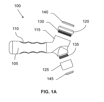
[0020] Figure 1A illustrates one embodiment of an ultrasound device shown
with a head assembly that is detached.
[0021] Figure 1B illustrates the ultrasound device of Figure 1A with the
head
assembly attached.
[0022] Figures 2A-2D illustrate various views of one embodiment of a
diaphragm.
[0023] Figure 3 illustrates a cross-section view of Figure 2C including
one
embodiment of an ultrasound transducer disposed within the diaphragm.
[0024] Figure 4A shows gel being inserted into a cavity of an ultrasound
device/probe.
[0025] Figure 4B shows the gel in an inserted state in the cavity of the
ultrasound device/probe.
[0026] Figure 5 illustrates another embodiment of an example ultrasound
probe with a gel cavity configured in the housing.
9
CA 02900213 2015-08-04
[0027] Figure 6 illustrates one embodiment of a block diagram of an
ultrasound device with energy generating components.
[0028] Figure 7 illustrates one embodiment of a block diagram of an
ultrasound device with a transducer controller that changes frequencies.
[0029] Figure 8A illustrates P cross-section top view of another embodiment
of
the diaphragm including a protrusion.
[0030] Figure 8B illustrates another embodiment of the preconfigured
medium
including a notch to correspond with the protrusion of the diaphragm in Fig.
8A.
[0031] Figure 80 illustrates the preconfigured medium from Fig. 8B
inserted
into the diaphragm of Fig. 8A.
[0032] Figures 9A and 9B illustrate another embodiment of the diaphragm
including a notch and the preconfigured gel with a protrusion, respectively.
DETAILED DESCRIPTION
[0033] Various embodiments of an ultrasound device are disclosed herein
that
are configured to operate with a controlled or predefined amount of gel (or
other
conductive medium) used during an ultrasound procedure. In one embodiment,
an ultrasound device is described herein that includes a diaphragm configured
with a recessed cavity/receptacle for containing a conductive medium. The
diaphragm is also referred to herein as a head assembly since the diaphragm is
part of the head of an ultrasound device. In another embodiment, a diaphragm
is
disclosed that is configured as a replaceable head for an ultrasound or other
imaging technology device where the diaphragm includes an ultrasound
transducer or other imaging technology transducer (e.g., piezoelectric
crystal)
and a cavity for containing a conductive medium.
CA 02900213 2015-08-04
[0034] With
reference to Fig. 1A and Fig. 1B, one embodiment of an
ultrasound device 100 is shown in a partially unassembled state (Fig. 1A) and
in
an assembled state (Fig. 1B). The device 100 is configured as a hand-held
device/probe including an elongated handle 105 that may include zero or more
finger grips 110 (e.g., indentations, ridges, and so on). The handle 105 is
connected to a head 115 that includes one or more sides that connect to a
diaphragm. In the illustrated "'embodiment, the head 115 includes two sides
where the first side includes diaphragm 120 and the second side includes
diaphragm 125.
[0035] In general as discussed herein, the diaphragm 120, 125 is the
component that is formed or connected as part of the head (sometimes referred
to as the nose) of an ultrasound device/probe. The diaphragm may also be an
acoustic member or acoustic lens such that ultrasound energy generated from a
transducer is directed and transmitted through the acoustic lens/diaphragm,
and
in imaging probes, echo signals are received from a subject through the
acoustic
lens/diaphragm.
[0036] In one
embodiment, diaphragm 120 is configured with a connector
130 that is threaded to insert and connect with a corresponding threaded
socket
in the head 115. Similarly, the second side of the head 115 may include a
connector 135 that is threaded for connecting with a threaded socket within
the
diaphragm 125. In another embodiment, the connectors 130 and 135 may be
configured as a quick-connect/disconnect device so that the diaphragms 120 and
125 can be connected by pushing and snapping into place or disconnected by
pulling off with a small amount of force. In another embodiment, the diaphragm
120 may be configured to slide on/off and connect by friction. Thus, in one
embodiment, the diaphragms 120 or 125 are configured as replaceable
components that can be removed and attached to other devices (e.g., attachable
and detachable). Being replaceable allows for different sized diaphragms to be
11
CA 02900213 2015-08-04
connected to the head 115 so that the same device 100 can be configurable with
different sized diaphragms and different sized transducers that may be
attached
within the diaphragm. In another embodiment, the head 115 and diaphragm 125
may be integral with each other (see example in Figure 5).
[0037] With reference to diaphragm 120, the diaphragm includes a recessed
cavity/receptacle that is configured to receive and contain/hold a conductive
medium 140 used during an ultrasound or imaging scan. The cavity is
configured to allow the conductive medium to be inserted into and removed from
the cavity. In one embodiment, the conductive medium 140 is a portion of gel
(e.g., preconfigured gel, gel pad) that is manufactured to maintain its
dimensions
(e.g., may be elastic with memory, flexible, and/or semi-solid or solid,
etc.). The
preconfigured medium 140 fits into the cavity, as seen in Fig. 1B where the
medium 140 is inserted into the cavity of diaphragm 120. Likewise, diaphragm
125 includes a cavity to receive a conductive medium 145 when used during a
scan. The diaphragm 120 is explained in more detail with reference to Figure
2.
[0038] With reference to Figures 2A-2D, one embodiment of diaphragm 120
(e.g., head assembly) is shown in a Top View Fig. 2A, Side View Fig. 2B, Cross-
Section View Fig. 2C through A-A of Fig. 2A, and a Perspective View Fig. 2D.
[0039] In one embodiment, the diaphragm 120 includes a housing formed
from metal, metallic, or other conductive material that functions with
ultrasound
energy (e.g., plastic or other acoustic conducting material). The diaphragm
120
includes a cavity/receptacle 200 that is configured to receive a conductive
medium. For example, the cavity 200 is a gel receiving cavity (e.g., a
receptacle
in which gel is inserted for an ultrasound procedure). The cavity 200 is
defined
by diaphragm surface 205 and a sidewall 210 that extends out from the
diaphragm surface 205. The diaphragm surface 205 is the outer surface of a
wall or partition 215 that forms the diaphragm and extends across the interior
of
the housing as seen in Figure 20. Stated another way, the diaphragm surface
12
CA 02900213 2015-08-04
205 is recessed within the housing from the top of the sidewall 210 to define
the
cavity 200 for receiving gel.
[0040] Thus
in one embodiment, the recessed diaphragm wall 215 defines
two cavities within the housing of the diaphragm 120, namely, cavity 200 and
cavity 220. The diaphragm surface 205 is shown as generally a circular shape
but other shapes may be used (e.g., oval, rectangular, area with curved edges,
flat or arced surface, polygon, and so on). In one embodiment, the diaphragm
surface 205 is substantially flat but may be arced depending on the desired
shape of the diaphragm 120. In another embodiment, the diaphragm wall 215
does not extend across the entire area of the housing but may extend a portion
out from the side wall 210 such that the wall 215 has an opening therethrough.
[0041]
Connector 130 may be threaded on either the outside or inside surface
of the housing. In another embodiment, the connector 130 may be configured as
a snap-on/snap-off connector (e.g., quick connect coupling) to attach to the
head
of an ultrasound device/probe. Other attachment mechanisms may be used
(e.g., friction fit, adhesion, and so on).
[0042] In one
embodiment, the sidewall 210 is a continuous edge or rim
around the perimeter of the diaphragm surface 205. In another embodiment, the
sidewall 210 may include one or more notches (not shown). A notch may be
used to assist with removing gel from within the cavity 200 by inserting a
finger in
the notch to access the gel within the cavity from the side and lift out the
gel. In
another embodiment, the sidewall 210 may be perforated or be configured as two
or more portions such as prongs that can hold a piece of solid gel (e.g., gel
140
shown in Fig. 1A and 1B).
[0043] The cavity 205 is configured as a containment area for receiving a
conductive medium (e.g., a gei shot, preconfigured piece of semi-solid gel).
In
one embodiment, the conductive medium is configured to correspond to fit into
the shape of the cavity 205. A piece of gel can be inserted into the cavity
200
13
CA 02900213 2015-08-04
where the gel is held in place by at least surface tension with the surface
205
and/or friction with the inside surface of the sidewall 210. In this manner,
the
diaphragm 120 self-contains the gel to be used during an ultrasound
scan/procedure so that the gel moves with the ultrasound device as the device
is
moved over a subject. Thus the diaphragm 120 maintains the position of the gel
piece relative to the transducer within the ultrasound device during movement
of
the ultrasound device. The cavity 200 and sidewall 210 form a mechanism for
holding and moving a piece of gel during a scan. When the scan is complete,
the
gel is simply removed from the cavity 200 and another piece of gel can be
inserted for a subsequent scan (see Figures 4A and 4B that show an example
piece of gel 140 being inserted into the cavity 200).
[0044] As
such, the amount of gel used during a scan is fully controlled by the
piece of preconfigured gel. Furthermore, the preconfigured gel provides for
greater sterility because pieces of gel can be packaged individually to
prevent
contamination. Dispensing and applying liquid gel on a patient in a random and
immeasurable manner is eliminated. Furthermore, using a controlled amount of
gel reduces the amount of gel needed for a scan, which can reduce the cost of
using gel.
[0045] Figure
2C illustrates a cross-section view of the diaphragm 120
through A-A of Figure 2A and side view of Fig. 2B. The various dimensions
shown are only exemplary of one embodiment. It is not intended to limit the
construction of the diaphragm 120 shown since the diaphragm can be formed
with different shapes and sizes.
[0046] With
reference to Figure 3, another embodiment of the cross-section
view of Figure 2C is shown. In Figure 3, a transducer 300 is positioned and
attached within the interior cavity 220. For example, the transducer 300 may
be
attached by an adhesive to inside
surface of the diaphragm wall 215,
attached by friction, or attached by contact with other assembled components
14
CA 02900213 2015-08-04
that hold the transducer 300 in place. In one embodiment, the transducer 300
is
positioned adjacent the gel receiving cavity 200 on the opposite side of the
diaphragm wall 215 such that ultrasound energy generated by the transducer
300 is directed towards and transmitted through the diaphragm wall 215 and the
gel receiving cavity 200.
[0047] In one embodiment, the transducer 300 may include one or more
electrical contacts 310 (e.g., pins, tabs, electrodes, wire connectors, and so
on)
to electrically connect the transducer 300 to a driving circuit and/or power
supply
when the diaphragm 120 is connected to an ultrasound device. In one
embodiment, the transducer is .a piezoelectric crystal for generating
ultrasound
waves.
[0048] With reference to Figure 4A, in another embodiment, the piece of
preconfigured gel 140 is shown being inserted into the cavity 200 of the
diaphragm 120 (or head 115). Figure 4B shows the gel 140 in an inserted state
in the cavity 200. As seen in Figure 4B, the cavity 200 is configured to
contain/enclose multiple sides of the preconfigured gel 140 while at least one
side of the preconfigured gel 140 is exposed (e.g., top surface). The exposed
surface is the surface that is placed in contact with the skin of a patient
(or other
object) to which ultrasound is applied.
[0049] In one embodiment, the diaphragm 120 is configured to convert the
head portion 115 of the ultrasound device from an existing configuration that
does not have a gel receiving cavity to a configuration that includes the gel
receiving cavity 200 after the diaphragm 120 is connected to the ultrasound
device. This may involve removing an existing head assembly and replacing it
with the diaphragm 120 or (depending on the configuration), attaching the
diaphragm 120 on top of an existing head assembly. Thus an existing ultrasound
device can be retrofitted to include the gel receiving cavity 200.
CA 02900213 2015-08-04
[0050] With reference to Figure 5, another embodiment of a hand-held
ultrasound probe/device 500 is shown that is configured with an integrated
head
assembly. For example, instead of the device having a detachable diaphragm
120 as in the embodiment of Figure 1A, the ultrasound device 500 includes a
housing that has a head portion 510 that is integrated with and forms side
wall
515. The side wall 515 defines a gel receiving cavity 520 similar to the
cavity
200 in Fig. 2D.
[0051] The side wall 515 extends around an acoustic member or acoustic
lens
525 through which ultrasound energy is transmitted from a transducer (not
shown). The transducer is positioned within the housing behind the acoustic
lens
525. With the gel receiving r3vity 520, a piece of preconfigured gel may be
inserted and contained within the cavity 520. The cavity 520 is configured to
hold
the preconfigured gel against the acoustic lens 525 and move the gel along a
patient as the ultrasound device 500 is moved. Thus the device 500 and the gel
are moved together. Other components may include a handle portion 530 and a
power supply cord 535 or may have an internal power source.
[0052] With the gel receiving cavity 520, preconfigured gel is used that
has a
predefined/measured amount of gel. Thus the gel provides a known thickness
and a consistent amount of gel during an ultrasound procedure. In this manner,
the device 500 (or device 100 from Figure 1A) is configured to provide and use
a
controlled amount of gel during a procedure, which eliminates the random
dispensing of liquid gel on a patient.
[0053] With reference to Figure 6, one embodiment of the components
within
a housing 600 that may be the housing of the ultrasound device 100 or 500 is
shown. The components are configured to generate and/or detect ultrasound
energy. In one embodiment, the housing 600 includes an energy generating
module 605 operative to generate a driving signal that can be transformed into
ultrasonic energy 610. The energy generating module 605 can be implemented
16
CA 02900213 2015-08-04
as a circuit board with electrical components that are electrically connected,
in
one embodiment. The energy generating module 605 includes a local power
source or receives power from a remote source via a power cord, an oscillator
615, and a driver component 620. There are many different types and
combinations of internal components that can be used to implement the
ultrasound device. Since they are not the focus of the present disclosure,
they
are not described in detail.
[0054] In one embodiment, the housing 600 also includes an ultrasound
transducer 625 having a piezoelectric component. The ultrasound transducer 625
is operative to receive the driving signal from the energy generating module
605
and transform the driving signal into ultrasonic energy 610. If the ultrasound
device is an imaging device, thr housing 600 may contain components to detect,
store, and convert received ultrasound signals. In another embodiment, the
ultrasound transducer 625 is part of the head assembly as previously described
(e.g., see Figure 3).
[0055] In one embodiment, the transducer 625 is a piezoelectric
transducer
that converts electrical energy into sound. Piezoelectric crystals have the
property of changing size when a voltage is applied, thus applying an
alternating
current (AC) across the crystal causes the crystal to oscillate at very high
frequencies, thus producing very high frequency sound waves.
[0056] The location at which a transducer focuses the sound can be
determined by the active transducer area and shape, the ultrasound frequency,
and the sound velocity of the propagation medium.
[0057] Since piezoelectric crystals generate a voltage when force is
applied to
them, the same crystal can be used as an ultrasonic detector/receiver. In
other
embodiments, separate transmitter and receiver components may be
implemented.
17
CA 02900213 2015-08-04
[0058] In another embodiment, a non-piezoelectric transducer may be
implemented. For example, the transducer 625 may be constructed of
magnetostrictive materials that change size when exposed to a magnetic field.
[0059] In another embodiment, the housing 600 may include an internal
memory for storing ultrasound data collected by the device. The housing 600
may include an interface for communicating the data from the memory to a
remote device. The ultrasound device 600 can be configured to communicate
the data via a wire connection and/or a wireless connection to a host machine
or
computer.
[0060] Alternating Frequency Embodiment
[0061] Therapeutic ultrasound treatment is customarily performed
manually
by a clinician. The clinician applies and moves a handheld ultrasound device
over an area of a patient. The area being treated on the patient is typically
larger
than the size of the head/tip of the ultrasound device. Thus the clinician
must
carefully move the ultrasound device across a patient's skin with a
coupling/conductive medium (e.g., layer of gel or lotion) between the
transducer
and the skin. The movement is also needed to avoid damaging the skin caused
by "hot spots" from the ultrasound device. For example, if the device is left
in
one location for too long, the continuous ultrasound energy can overexpose and
burn the skin. This may happen in a few seconds depending on the intensity of
the ultrasound.
[0062] Movement speed of the transducer during treatment varies widely
from
one clinician to another. Therefore, many clinicians incorrectly apply the
ultrasound by moving the transducer too fast, by not using enough coupling
medium, by not moving the transducer, by trying to treat too large of an area,
by
not keeping the transducer in contact with the patient or other faults.
18
CA 02900213 2015-08-04
[0063] Thus, in one embodiment, the mobile ultrasound device 100 or 500
(see Fig. 1 or 5, respectively) is configured to automatically change
ultrasound
frequencies at periodic intervals. With reference to Figure 7, one embodiment
an
ultrasound device 700 is shown in block diagram form, which is a based on the
ultrasound device 600 of Figure 6. In Figure 7, the device 700 includes a
transducer controller 705 that controls the transducer 625 of a manually-
operated
ultrasound device to perform an alternating sweep of different frequencies
based
on a time period.
[0064] The transducer controller 705 is electrically connected to the
transducer 625 via the energy generating module 605. For example, the
transducer controller 705 can be a logic component that is part of the energy
generating module 605 or can externally control the module 605 as a different
component within the handheld device 700. In another embodiment, the
transducer controller 705 is Ir. iplemented as logic within a host computer
that
sends control signals to the device 700 so that desired frequencies are
generated at different times.
[0065] In one embodiment, the transducer controller 705 is a
programmable
logic configured to control the transducer 625 to generate selected
frequencies of
ultrasound at selected time periods. For example, the transducer 625 can be
controlled to automatically alternate between two or more different
frequencies at
predefined time intervals (e.g., alternate between 1 MHz and 3 MHz every 4
seconds). Of course, other frequencies can be used and the device can cycle
between a set of predefined frequencies. In one embodiment, the transducer
controller 705 is configured to cause the transducer 625 to operate at
different
frequencies by changing the voltage or current that is applied to the
transducer
625 from a power source via the energy generating module 605.
[0066] In one embodiment, the device 700 includes frequency settings 710
that are predefined and/or programmable. The frequency settings 710 include
19
CA 02900213 2015-08-04
parameters stored in a memory that indicate various frequencies and time
periods for changing between selected frequencies during operation of the
ultrasound device 700. Default parameters may be set for the device and/or
parameters may be selected by a user via a user interface. The transducer
controller 705 may be configured to read selected parameters from the
frequency
settings 710 and control the transducer 625 according to those parameters.
[0067] In one embodiment, the transducer controller 705 is configured
with a
memory that contains the pre-defined frequency settings 710. The pre-defined
settings 710 may be programmable via a user interface. In one embodiment,
transducer controller 705 is configured using firmware that executes an
algorithm
for changing the frequency of the transducer 625 between two or more selected
frequencies. The frequency can be changed based on a designated trigger
event (e.g., a selected time interval, detected motion of the ultrasound
device
moving a certain distance, and so on). If motion is the trigger event, then
the
frequency is changed when th6 ultrasound device is moved, for example, every
2-3 inches or if the device is not moved for a threshold time period (e.g., to
avoid
overexposing one location to the same ultrasound frequency).
[0068] As an example operation, consider a physical therapy application
where the frequency settings are selected to alternate between 1 MHz and 3
MHz every 4 seconds. Upon initiating an ultrasound procedure, the transducer
controller 705 is configured to activate the transducer 625 (via the energy
generating module 605) to operate at a first frequency (e.g., around 1 MHz).
Assuming that a clinician operating the hand-held device 700 is moving the
device 700 across a patient's skin at some speed, the transducer controller
705
changes parameters after a time interval (e.g., 4 seconds) causing the
transducer 625 to operate at a second frequency (e.g., around 3 MHz).
[0069] After the next time period, the process repeats by alternating
between
the 1 MHz and 3 MHz frequencies. As the ultrasound device 700 is moved along
CA 02900213 2015-08-04
the skin (or back and forth along an area), the alternating frequencies offer
a
good compromise between sufficiently deep penetration and adequate heating of
the treatment area using varying ultrasound frequencies and exposure levels.
[0070] In one embodiment, device 700 is used in combination with a
preconfigured piece of conductive medium (e.g., gel 140; see Fig. 1 or 4A)
that is
infused with a medicine/drug. Thus, when device 700 automatically changes
frequencies, the change helps to drive the medicine/drug from the conductive
medium into the skin of the patient for absorption.
[0071] In another embodiment, the ultrasound device 700 is configured to
provide a signal (e.g., audible, visual (light), or both) each time the
frequency
changes. In another embodiment, the ultrasound device 700 may include a
display screen that displays the current operating frequency.
[0072] In general, the device 700 simplifies the ultrasound procedure by
not
requiring the clinician to stop and manually change settings (e.g., changing a
setting in a host device) in order to change the frequency of the ultrasound.
This
also helps to reduce human error in applying incorrect settings for an
ultrasound
procedure.
[0073] The automatic frequency changes of the device 700 provide
additional
safety to a patient. For example, if the clinician does not move the device
700
fast enough or maintains the device 700 in one location for too long of a time
period, the device 700 is configured to change frequencies every few seconds.
Thus, this reduces the risk of burning or damaging the skin caused by
overexposure to the same ultrasound frequency at the same location during the
therapy procedure.
[0074] Diaphragm With Protrusion Embodiment
[0075] With reference to Fig. 8A, another embodiment of the diaphragm
120
is shown that includes an interior protrusion 800. Fig. 8A is a top view of
the
21
CA 02900213 2015-08-04
diaphragm 120 similar to Fig. 2A that shows the sidewall 210 and cavity 200.
The sidewall 210 is shown in cross-section. In Fig. 8A, the inner surface of
the
sidewall 210 includes one or more protrusions 800 that project out from the
sidewall 210 and toward the cavity 200. For example, the protrusion 800 is a
rib
or other projection that may be configured in a desired shape and orientation.
The protrusion 800 may extend vertically or horizontally along the sidewall
210
and there may be multiple protrusions 800 distributed along the inner wall.
[0076] In one
embodiment, the protrusion 800 is configured to assist in
locking or otherwise holding a preconfigured gel 140 in place in the gel
receiving
cavity 200. For example, Fig. 8B illustrates another embodiment of the
preconfigured gel 140 that includes a notch 810. The notch 810 is configured
with a shape that corresponds to the protrusion 800 for connection
therebetween.
In one example, the notch 810 is a female counterpart of the protrusion 800.
[0077] Fig.
8C illustrates the preconfigured gel 140 being aligned and inserted
into the receiving cavity 200. The gel 140 is shown as a dashed outline as it
sits
in the receiving cavity 200. With protrusion 800 inserted into notch 810 of
the gel
140, movement of the gel 140 is restricted to ensure that the gel 140 does not
inadvertently fall out during an ultrasound procedure.
[0078] In
other embodiment, the protrusion 800 and notch 810 may have
geometries and/or shapes other than the circular shape shown in Figs. 8A and
8B, respectively. In
other embodiments, both the sidewall 210 and the
preconfigured gel 140 may have protrusions that are configured to interlock
with
each other (e.g., one protrusion fits on top of or under the other
protrusion). For
example, the sidewall 210 may have one or more lips, edges, or rings that
project
outward and are positioned to engage a corresponding lip, edge, or ring on the
preconfigured gel 140.
[0079] With
reference to Figs. 9A and 9B, a reversed embodiment of Figs. 8A
and 8B is shown where the diaphragm 120 is configured with a notch 900 in the
22
CA 02900213 2015-08-04
sidewall 210 and the preconfigured gel 140 is configured with a protrusion 910
extending out from the preconfigured gel 140. Thus when the gel 140 is
inserted
into the receiving cavity 200, the protrusion 910 of the gel is aligned and
inserted
into the notch 900. Of course, other shapes and geometries may be
implemented.
[0080] Definitions
[0081] The following includes definitions of selected terms employed
herein.
The definitions include various examples and/or forms of components that fall
within the scope of a term and that may be used for implementation. The
examples are not intended to be limiting. Both singular and plural forms of
terms
may be within the definitions.
[0082] The term "conductive medium" is used to refer to a substance that
is
used during an ultrasound procedure that assists in coupling the ultrasound
device/probe head or applicator tip to a subject (e.g., the skin of a patient
or other
surface) and conducts ultrasound energy. Typically, the conductive medium is
ultrasound gel but other substances can be used such as shampoo, hairstyling
gel, hand lotion, hand sanitizer, Jquid dishwashing detergent, olive oil (or
other oil
based substances), or other substance that is appropriate to function with an
ultrasound device. These substances may be preconfigured into a semi-solid or
solid form and used with the receiving cavity 200. References to the term
"gel" is
intended to refer to any of these conductive media that is appropriate for an
ultrasound procedure.
[0083] References to "one embodiment", "an embodiment", "one example",
"an example", and so on, indicate that the embodiment(s) or example(s) so
described may include a particular feature, structure, characteristic,
property,
element, or limitation, but that not every embodiment or example necessarily
includes that particular feature, structure, characteristic, property, element
or
23
CA 02900213 2015-08-04
limitation. Furthermore, repeated use of the phrase "in one embodiment" does
not necessarily refer to the same embodiment, though it may.
[0084] While example systems, methods, and so on have been illustrated by
describing examples, and while the examples have been described in
considerable detail, it is not the intention of the applicants to restrict or
in any way
limit the scope of the appended claims to such detail. It is, of course, not
possible to describe every conceivable combination of components or
methodologies for purposes of describing the systems, methods, and so on
described herein. Therefore, the disclosure is not limited to the specific
details,
the representative apparatus, and illustrative examples shown and described.
Thus, this disclosure is intended to embrace alterations, modifications, and
variations that fall within the scope of the appended claims.
[0085] "Logic", as used herein, includes computer or electrical
hardware,
firmware, a non-transitory electronic medium that stores instructions/data,
and/or
any combinations of these to perform a function(s) or an action(s), and/or to
cause a function or action from another logic, method, and/or system. Logic
may
include a microprocessor configured to execute an algorithm, a discrete logic
(e.g., ASIC), an analog circuit, a digital circuit, a programmed logic device,
a
memory device containing instructions, and so on. Logic may include at least
one circuit, one or more gates, combinations of gates, or other circuit
components. Where multiple logical logics are described, it may be possible to
incorporate the multiple logical logics into one physical logic. Similarly,
where a
single logical logic is described, it may be possible to distribute that
single logic
between multiple logics. Logic can be used to implement one or more of the
components described herein or their equivalents.
[0086] To the extent that the term "includes" or "including" is employed
in the
detailed description or the claims, it is intended to be inclusive in a manner
24
CA 02900213 2015-08-04
similar to the term "comprising" as that term is interpreted when employed as
a
transitional word in a claim.
[0087] To the extent that the term "or" is used in the detailed
description or
claims (e.g., A or B) it is intended to mean "A or B or both". When the
applicants
intend to indicate "only A or B but not both" then the phrase "only A or B but
not
both" will be used. Thus, use of the term "or" herein is the inclusive, and
not the
exclusive use.