Note: Descriptions are shown in the official language in which they were submitted.
I
SAFETY RAILING MOUNT FOR ROOF
This invention relates to a safety railing mount for a roof of a building.
BACKGROUND OF THE INVENTION
In times past when concern about safety was less developed, workers
.. on roofs simply accepted the risk of falling and carried out their tasks
without safety
harnesses or safety rails.
In more enlightened times, requirements have been set forth that all
workers at risk of falling must be protected. In many cases this is done by
harnesses
and fall restraint cables but Often this is restrictive, particularly where
there are a
number of workers in the area to be protected.
An alternative approach is to provide a safety fence around the
perimeter of the area. A number of proposals have been made to provide such a
construction. Typically this is done by constructing a full scaffolding around
the
perimeter but this is expensive and time consuming. Alternative constructions
have
been provided but often these do not provide sufficient stability.
SUMMARY OF THE INVENTION
It is one object of the invention to provide an apparatus for mounting
safety railing to a roof.
According to a first aspect of the invention there is provided a building
comprising:
a roof at a raised height above ground surrounding the building;
CA 2900471 2018-08-03
2
the roof having a vertical face plate extending along the length of the
roof;
and an apparatus for mounting a safety railing to the roof, the apparatus
comprising:
a mounting plate member consisting of a single sheet of metal having a
flat substantially planar mounting plate portion with an edge flange portion
bent at a
right angle to the flat mounting plate portion;
the flange portion mounted by screw fasteners to the vertical face plate
of the roof with the flat mounting plate portion extending outwardly from the
vertical
face plate at a right angle thereto;
a receiving hole through the mounting plate portion;
a vertical support post separate from the mounting plate member and
extending through the hole to form an upper portion of the post above the
mounting
plate portion and a lower portion of the post extending downwardly from the
mounting
plate portion to a bottom end of the post at the ground;
a horizontal safety rail arrangement supported by the upper portion of
the vertical post above the mounting plate member;
and a support on the ground below the mounting plate member fef
engaging and supporting the bottom end of the post so as to extend from the
support
at the ground through the hole in the mounting plate to the safety rail
arrangement
with the support maintaining the post in a vertical position and the mounting
plate
member preventing horizontal movement of the post.
CA 2900471 2018-08-03
3
According to a second aspect of the invention there is provided a
building comprising:
a roof at a raised height above ground surrounding the building;
the roof having a vertical face plate extending along the length of the
roof;
and an apparatus for mounting a safety railing to the roof, the apparatus
comprising:
a mounting plate member consisting of a single sheet of metal defining a
flat substantially planar mounting plate portion;
one edge portion of the flat mounting plate portion being mounted by
screw fasteners passing through holes in the edge portion to a horizontal top
edge of
the vertical face plate of the roof with the flat mounting plate portion
extending
outwardly from the vertical face plate at a right angle thereto;
a receiving hole through the mounting plate portion;
a vertical support post separate from the mounting plate member and
extending through the hole to form an upper portion of the post above the
mounting
plate portion and a lower portion of the post extending downwardly from the
mounting
plate portion to a bottom end of the post at the ground;
a horizontal safety rail arrangement supported by the upper portion of
the vertical post above the mounting plate member;
and a support on the ground below the mounting plate member ter
engaging and supporting the bottom end of the post so as to extend from the
support
CA 2900471 2018-08-03
4
at the ground through the hole in the mounting plate to the safety rail
arrangement
with the support maintaining the post in a vertical position and the mounting
plate
member preventing horizontal movement of the post.
According to a third aspect of the invention there is provided a building
comprising:
a roof at a raised height above ground surrounding the building;
the roof having a vertical face plate extending along the length of the
roof and an inclined roof deck;
and an apparatus for mounting a safety railing to the roof, the apparatus
comprising:
a mounting plate member consisting of a single sheet of metal defining a
flat substantially planar plate portion;
one edge portion of the flat mounting plate portion being mounted by
screw fasteners passing through holes therein to the inclined roof deck with
the flat
mounting plate portion extending outwardly from the inclined roof deck at an
angle to
the vertical face plate different from 90 degrees and defined by the inclined
roof deck;
a receiving hole through the mounting plate portion;
a vertical support post separate from the mounting plate member and
extending through the hole to form an upper portion of the post above the
mounting
plate portion and a lower portion of the post extending downwardly from the
mounting
plate portion to a bottom end of the post at the ground;
CA 2900471 2018-08-03
5
a horizontal safety rail arrangement supported by the upper portion of
the vertical post above the mounting plate member;
and a support on the ground below the mounting plate member far
engaging and supporting the bottom end of the post so as to extend from the
support
at the ground through the hole in the mounting plate to the safety rail
arrangement
with the support maintaining the post in a vertical position and the mounting
plate
member preventing horizontal movement of the post;
wherein the receiving hole is dimensioned relative to the post to allow
the post to pass through the hole while the post is at said angle to the
plate.
BRIEF DESCRIPTION OF THE DRAWINGS
One embodiment of the invention will now be described in conjunction
with the accompanying drawings in which:
Figure 1 is an isometric view of a first embodiment of the present
invention.
Figure 2 is an isometric view of a second embodiment of the present
invention,
Figure 3 is an isometric view of the mounting plate portion of the
embodiment of Figure 2 of the present invention.
Figure 3A is an isometric view of the mounting plate portion of the
embodiment of Figure 1 of the present invention.
Figure 4 is a cross sectional view along the lines 4 ¨ 4 of figure 1.
CA 2900471 2018-08-03
6
Figure 5 is a cross sectional view along the lines 5 ¨ 5 of figure 1.
Figure 6 is a schematic isometric view of the plate members of Figure
3A mounted at the edge of a pitched roof of the present invention.
In the drawings like characters of reference indicate corresponding parts
in the different figures.
DETAILED DESCRIPTION
Figures 1 and 2 illustrate first and second embodiments of the present
invention. Illustrated is a house 1, more specifically a partial roof 3 of the
house.
Generally, house roof construction has a face plate 5 which runs along the
length of
the house. The face plate is arranged to support the soffit and fascia of the
house.
When building a home, specifically working on the roof of a house, there are
is a
danger of a worker falling off the roof. The face plate is generally a 2x6
inch length of
lumber whereby the face plate is mounted with the wide portion 7 is mounted
vertically on the house roof. The face plate is suitable secured to the house.
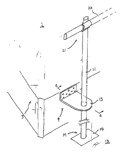
As illustrated in figure 1, a safety rail mount for a roof 9 is mounted to
the face plate of the roof system. Vertical posts 11 are supported by a
mounting plate
13. The posts are arranged to extend downwardly to a suitable support surface
15
such as the ground or a base plate anchored to the ground. The post has a
support
plate 17 at a bottom end 19 which allows the post to be placed on the
supporting
surface. At a top end 21 of the post is a guide rail 23 arranged to prevent
workers
CA 2900471 2018-08-03
7
from falling off the building so as to avoid the necessity for a harness
arrangement
worn by the worker.
The posts are supported vertically by the mounting plate. In a first
embodiment of the mounting plate, as illustrated in figure 3 and 4, the plate
is
arranged to mount to an outer face 25 of the face plate of the roof system.
The plate
has a horizontal section 27 which is arranged to extend horizontally from the
outer
face of the face plate. A receiving hole 29 is arranged to receive the
vertical post and
is positioned on the horizontal section such that the post is positioned
sufficient
distance from the edge of the roof allowing the post to extend downwardly to
the
ground and vertically for receiving the guard rails.
A vertical mount 31 of the mounting plate extends vertically from the
horizontal plate such that the plate can be mounted to the outer face of the
face plate.
The vertical mount has holes 33 to receive mounting bolts 35 for sufficiently
mounting
the plate to the face plate. Some of the holes can be located at the junction
between
the angle parts so as to pass through the plate into the face plate at an
angle of
roughly 45 degrees to the plate.
In a second embodiment of the present invention, as illustrated in figure
3A and 5 the mounting plate is arranged to mount to a top face 37 of the face
plate or
on top of the plywood fastened to the face plate and underneath the shingles
if
already applied. A horizontal mount portion 39 of the mounting plate extends
from the
horizontal plate of the mounting plate. The plate has a horizontal section 41
which is
arranged to extend horizontally or at small angle downwardly and outwardly
from the
CA 2900471 2018-08-03
8
outer face of the face plate. A receiving hole 43 is arranged to receive the
vertical
post and is positioned on the section 41 such that the post is positioned
sufficient
distance from the edge of the roof allowing the post to extend downwardly to
the
ground outwardly of the eavestrough, if already in place, and vertically for
receiving
the guard rails.
The horizontal mount has holes 45 to receive mounting screw fasteners
47 for sufficiently mounting the plate to the top side of face plate.
The receiving hole 43 has a recessed portion 49 turned downwardly at
the edge so that the vertical post can be inserted easily therethrough. The
plate is
arranged support the post in a vertical position preventing horizontal
movement of the
post. The hole is slightly larger than the post to allow the plate to lie at
an angle to the
post when attached to the roof deck due to the pitch of the roof.
Alternatively the
plate can be bent at an angle matching that of the deck so that the portion of
the plate
which contains the hole is located at right angles to the post.
In Figure 6 is shown the plates 13 of Figure 3 located along the
horizontal faceplate at one side of the building and along an end roof rafter
100. In
both cases the edge portion 39 of the plate is tucked under the shingles and
fastened
by downwardly extending screws into the face plate and into the roof rafter.
In both
cases the plates are inclined from the horizontal due to the pitch of the
roof. Each
plate is associated with a respective vertical post extending to the base
plate at the
ground and two or more horizontal rails are applied to the portion of the post
above
the plate.
CA 2900471 2018-08-03
9
The mounting plate consists of an integral plate and is formed from a
single sheet of metal with a portion for screw fastening to the face plate and
a plate
portion extending outwardly from the roof and containing the hole at a
position spaced
outwardly sufficiently to clear the eavestrough,
Where shingles are already applied, the mounting plate is located with
its edge underneath the shingles.
The base plate is fastened to the ground by stakes or other fasteners to
prevent side to side movement at the ground.
The receiving hole is dimensioned relative to the post to allow the post
to pass through the holes while at an angle to the plate different from 90
degrees to
allow the plate to be placed at an angle defined by the roof pitch.
The safety rails can be attached to the post by scaffolding clamps or
similar tubular clamps which hold the rails at a fixed height on the post.
CA 2900471 2018-08-03