Note: Descriptions are shown in the official language in which they were submitted.
CA 02900651 2015-08-07
WO 2014/124444
PCT/US2014/015819
FUEL-CELL SYSTEMS OPERABLE IN MULTIPLE MODES FOR
VARIABLE PROCESSING OF FEEDSTOCK MATERIALS AND
ASSOCIATED DEVICES, SYSTEMS, AND METHODS
CROSS-REFERENCE TO RELATED APPLICATION
[0001] The present application claims priority to U.S. 13/764,346, filed
February
11, 2013, which is a continuation-in-part and is related to U.S. Application
No,
13/584,748, filed August 13, 2012, which claims priority to U.S. Provisional
Application
No. 61/523,270, filed August 12, 2011. The foregoing applications are
incorporated
herein by reference. To the extent the foregoing applications and/or any other
materials incorporated herein by reference conflict with the present
disclosure, the
preset disclosure controls.
TECHNICAL FIELD
[0002] The present disclosure is directed generally to devices, systems,
and
methods for variable processing of feedstock materials to form useful reaction
products and/or to generate electricity. In a particular embodiment, a fuel
cell and a
fuel-cell system are operable in a first mode for thermally decomposing a
feedstock
material without generating electricity and in a second mode for utilizing
portions of
the feedstock material and generating electricity. For example, a hydrocarbon
feedstock material can decompose thermally to form hydrogen and carbon (e.g.,
as a
structural material) in a first mode and electrolytically form carbon dioxide,
electrical
current, and water in a second mode. In another example, a silane feedstock
material
can thermally decompose to form hydrogen and silicon (e.g., as a structural
material)
in a first mode and electrolytically form silicon dioxide, electrical current,
and water in
a second mode.
BACKGROUND
[0003] Renewable energy sources such as solar, wind, wave, falling water,
and
biomass have tremendous potential, but various technical challenges have
prevented
their widespread adoption. For example, using renewable energy sources in the
-1-
CA 02900651 2015-08-07
WO 2014/124444
PCT/US2014/015819
production of electricity is dependent on the availability of the energy
sources, which
can be intermittent. Solar energy is limited by the sun's availability (i.e.,
daytime only);
wind energy is limited by the variability of wind; falling water energy is
limited by
droughts; and biomass energy is limited by seasonal variances. As a result of
these
and other factors, much of the energy from renewable sources, captured or not
captured, tends to be wasted.
[0004] The inefficiencies associated with conventional approaches to
capturing
and storing energy often lead to high costs for producing energy from
renewable
energy sources. These high costs limit the widespread adoption of renewable
energy
sources in many regions of the world. Thus, the world continues to rely on oil
and
other fossil fuels as primary energy sources because, at least in part,
government
subsidies and other programs supporting technology developments associated
with
fossil fuels make it deceptively convenient and seemingly inexpensive to use
such
fuels. At the same time, the replacement cost for the expended resources, and
the
costs of environmental degradation, health impacts, and other byproducts of
fossil-fuel
use are not included in the purchase price of the energy resulting from these
fuels.
[0005] In light of the foregoing and other drawbacks currently associated
with
sustainably using renewable resources, there remains a need for improving the
efficiencies and commercial viabilities of producing products and fuels with
such
resources.
BRIEF DESCRIPTION OF THE DRAWINGS
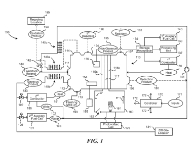
[0006] Figure 1 is a schematic block diagram of a fuel-cell system
configured in
accordance with an embodiment of the presently disclosed technology.
[0007] Figure 2 is a partially schematic illustration of a fuel cell
operating in a first
mode in accordance with an embodiment of the presently disclosed technology.
[0008] Figure 3 is a partially schematic illustration of a fuel cell
operating in a
second mode in accordance with an embodiment of the presently disclosed
technology.
[0009] Figure 4 is a partially schematic illustration of a system that
includes
multiple fuel cells connected in series in accordance with another embodiment
of the
presently disclosed technology.
-2-
CA 02900651 2015-08-07
WO 2014/124444
PCT/US2014/015819
[0010] Figure
5 is a partially schematic, partially cross-sectional illustration of a
system having a reactor with transmissive surfaces in accordance with an
embodiment of the disclosed technology.
[0011] Figure
6 is a partially schematic, cut-away illustration of a portion of a
reactor having transmissive surfaces positioned annularly in accordance with
an
embodiment of the disclosed technology.
[0012] Figure
7 is a partially schematic, partially cross-sectional illustration of a
system having a reactor with a re-radiation component in accordance with an
embodiment of the presently disclosed technology.
[0013] Figure
8 illustrates absorption characteristics as a function of wavelength
for a representative reactant and re-radiation material, in accordance with an
embodiment of the presently disclosed technology.
[0014] Figure
9 is an enlarged, partially schematic illustration of a portion of the
reactor shown in Figure 7 having a re-radiation component configured in
accordance
with a particular embodiment of the presently disclosed technology.
[0015] Figure 10 is a schematic cross-sectional view of a thermal transfer
device
configured in accordance with an embodiment of the present technology.
[0016] Figures 11A and 11B are schematic cross-sectional views of thermal
transfer
devices configured in accordance with other embodiments of the present
technology.
[0017] Figure 12A is a schematic cross-sectional view of a thermal transfer
device
operating in a first direction in accordance with a further embodiment of the
present
technology, and Figure 12B is a schematic cross-sectional view of the thermal
transfer
device of Figure 12A operating in a second direction opposite the first
direction.
[0018] Figure
13 is a partially schematic illustration of a heat pump suitable for
transferring heat in accordance with an embodiment of the present technology.
[0019] Figure
14 is a partially schematic illustration of a system having a solar
concentrator that directs heat to a reactor vessel in accordance with an
embodiment
of the disclosed technology.
-3-
CA 02900651 2015-08-07
WO 2014/124444
PCT/US2014/015819
[0020] Figure 15 is a partially schematic, enlarged illustration of a
portion of a
reactor vessel, including additional features for controlling the delivery of
solar energy
to the reaction zone in accordance with an embodiment of the disclosed
technology.
[0021] Figure 16 is a partially schematic, cross-sectional illustration of
an
embodiment of a reactor vessel having annularly positioned product removal and
reactant delivery systems in accordance with an embodiment of the disclosure.
[0022] Figure 17 is a partially schematic, partial cross-sectional
illustration of a
system having a solar concentrator configured in accordance with an embodiment
of
the present technology.
[0023] Figure 18 is a partially schematic, partial cross-sectional
illustration of an
embodiment of the system shown in Figure 1 with the solar concentrator
configured to
emit energy in a cooling process, in accordance with an embodiment of the
disclosure.
[0024] Figure 19 is a partially schematic, partial cross-sectional
illustration of a
system having a movable solar concentrator dish in accordance with an
embodiment
of the disclosure.
[0025] Figure 20 is a partially schematic illustration of a system having a
reactor
with facing substrates for operation in a batch mode in accordance with an
embodiment of the presently disclosed technology.
[0026] Figure 21 is a partially schematic, partially cross-sectional
illustration of a
reactor system that receives energy from a combustion engine and returns
reaction
products to the engine in accordance with an embodiment of the presently
disclosed
technology.
[0027] Figure 22 is a partially schematic, cross-sectional illustration of
a reactor
having interacting endothermic and exothermic reaction zones in accordance
with an
embodiment of the disclosure.
DETAILED DESCRIPTION
1. Overview
[0028] Several examples of devices, systems, and methods for carrying out
reactions within fuel cells and upstream and/or downstream of fuel cells in
fuel-cell
systems are described below. In some embodiments, a fuel-cell system and/or a
fuel
-4-
CA 02900651 2015-08-07
WO 2014/124444
PCT/US2014/015819
cell within the fuel-cell system can be used in accordance with multiple
operational
modes. For example, a first mode can include performing a non-electricity-
generating
reaction on a feedstock material to produce one or more first-mode reaction
products.
In some embodiments, the non-electricity-generating reaction can be a thermal-
decomposition reaction. A second mode can include performing an electricity-
generating reaction on a feedstock material to produce one or more second-mode
reaction products and electrical current. In
some embodiments, the electricity-
generating reaction can be an electrolytic-decomposition reaction. In the case
of
hydrocarbon feedstock materials, for example, the first mode can be an
internal-
reforming mode and the second mode can be a direct-hydrocarbon fuel cell mode.
Furthermore, with respect to hydrocarbon and non-hydrocarbon feedstock
materials,
the first mode can be a chemical-production mode (e.g., primarily directed to
the
production of chemical fuels, precursors, and/or other useful chemical
products) and
the second mode can be an electricity-production mode (e.g., primarily
directed to the
production of electrical current).
[0029]
Reaction products from operation in the first and/or second modes can be
put to a variety of suitable non-wasteful uses. The reaction products from
operation in
the first mode can include, for example, gaseous fuels (e.g., hydrogen), other
useful
gaseous materials (e.g., halogen gases), and/or useful non-gaseous materials
(e.g.,
carbon and/or silicon). Particular embodiments are described below in the
context of
producing non-gaseous materials, e.g., that are collected at a material
collector of the
fuel-cell system. In other embodiments, the collector can collect gaseous
materials.
The reaction products from operation in the second mode can include, for
example,
useful oxidation products (e.g., carbon dioxide, carbon monoxide, silicon
dioxide, and
halogen gases) and/or useful reduction products (e.g., water and hydrogen
halides).
Accordingly, fuel-cell systems configured in accordance with at least some
embodiments of the present technology can produce clean-burning chemical fuel
(e.g., hydrogen), repurpose carbon, silicon, and/or other constituents of
feedstock
materials (e.g., for use in durable goods), and generate electricity. In some
cases,
constituents of feedstock materials can be used (e.g., in durable goods)
without
further processing. In other cases, constituents of feedstock materials can be
further
processed into polymers, carbon composites, and/or other useful materials.
Although
the following description provides many specific details of representative
examples in
-5-
CA 02900651 2015-08-07
WO 2014/124444
PCT/US2014/015819
a manner sufficient to enable a person skilled in the relevant art to
practice, make, and
use the representative examples, several of the details and advantages
described
below may not be necessary with respect to certain examples of the present
technology. Additionally, the present technology may include other examples
that are
not described here in detail.
[0030] References throughout this specification to "one example," "an
example,"
"one embodiment," or "an embodiment" mean that a particular feature,
structure,
process, or characteristic described in connection with the example is
included in at
least one example of the present technology. Thus, the occurrences of the
phrases
"in one example," "in an example," "one embodiment," "an embodiment," or the
like in
various places throughout this specification are not necessarily all referring
to the
same example. Furthermore, the particular features, structures, routines,
steps, or
characteristics may be combined in any of a number of suitable manners in one
or
more examples of the present technology. The headings provided herein are for
convenience only and are not intended to limit or define the scope or meaning
of the
present technology.
[0031] Certain embodiments of the present technology described below may
take the form of computer-executable instructions, including routines executed
by a
programmable computer or controller. Those skilled in the relevant art will
appreciate
that the present technology can be practiced on computer or controller systems
other
than those shown and described below. Furthermore, the present technology can
be
embodied in a special-purpose computer, controller, or data processor that is
specifically programmed, configured, or constructed to perform one or more of
the
computer-executable instructions described below. Accordingly, the terms
"computer"
and "controller" as generally used herein refer to any data processor and can
include
internet appliances, hand-held devices, multi-processor systems, programmable
consumer electronics, network computers, mini-computers, and the like. The
present
technology can also be practiced in distributed environments where tasks or
modules
are performed by remote processing devices that are linked through a
communications network. Aspects of the present technology described below may
be
stored or distributed on computer-readable media, including magnetic or
optically
readable or removable computer discs as well as media distributed
electronically over
networks. In particular embodiments, data structures and transmissions of data
-6-
CA 02900651 2015-08-07
WO 2014/124444
PCT/US2014/015819
particular to aspects of the present technology are also encompassed within
the
scope of the present technology. The present technology encompasses methods of
both programming computer-readable media to perform particular steps and
executing
the steps.
2. Representative Fuel-Cell Systems and Associated Methodologies
[0032] Figure 1 is a schematic block diagram illustrating selected
components of
a fuel-cell system 100 configured in accordance with an embodiment of the
present
technology. The system 100 can include a fuel cell 110 (e.g., a first fuel
cell) that
performs multiple functions. In some embodiments, the system 100 includes a
first
electrode 115a, a second electrode 115b, and an ion-transport medium 117
(e.g., an
electrolyte or an electrolyte membrane) between the first and second
electrodes 115a,
115b. Depending on selected operations of the system 100, the first electrode
115a
can serve as an anode and the second electrode 115b can serve as a cathode,
the
first electrode 115a can serve as a cathode and the second electrode 115b can
serve
as an anode, or the first and second electrodes 115a, 115b can function as
neither
anodes nor cathodes (e.g., the first and second electrodes 115a, 115b can be
electrically dormant). The ion-transport medium 117, for example, can be a
polymer
membrane, an aqueous alkaline solution, a molten carbonate, a ceramic oxide
(e.g.,
alumina or zirconium oxide), a spine!, a nanostructure, or another material
suitable for
ion-transport.
[0033] The system 100 can receive a feedstock material 180 directed from a
feedstock source (not shown) to a first port 111 of the fuel cell 110.
Although
particular examples are described below primarily in the context of
hydrocarbon
feedstock materials 180, other suitable feedstock materials 180 can also be
used. In
some embodiments, the feedstock material 180 can include a compound containing
hydrogen, a halogen, boron, nitrogen, a transition metal, or a combination
thereof, as
constituent elements. Suitable feedstock materials 180 can include, for
example,
hydrocarbons (e.g., methane), boranes (e.g., diborane), silanes (e.g.,
monosilane),
nitrogen-containing compounds (e.g., ammonia), sulfides (e.g., hydrogen
sulfide),
alcohols (e.g., methanol), alkyl halides (e.g., carbon tetrachloride,
chloroform,
dichloromethane, fluorocarbons (e.g., carbon tetrafluoride), and
chlorofluorocarbons),
aryl halides (e.g., chlorobenzene), and hydrogen halides (e.g., hydrochloric
acid),
-7-
CA 02900651 2015-08-07
WO 2014/124444
PCT/US2014/015819
among others. In some cases, the feedstock material 180 can be a manmade or
natural source of embodied energy or material that would otherwise be wasted
or
underutilized. Furthermore, the feedstock material 180 may be an environmental
contaminant (e.g., a toxic substance and/or a contributor to climate change).
Accordingly, in some cases, the system 100 can be used in the context of
environmental remediation or waste processing.
[0034] In some embodiments, the system 100 can be configured for use in
close
proximity to a suitable source of the feedstock material 180. For example, the
system
100 can be configured for use near a landfill for processing methane that
would
otherwise be flared or released into the atmosphere. As another example, the
system
100 can be configured for use underwater or on a floating or anchored platform
for
processing ocean biomass and/or methane hydrates from the ocean floor.
Similarly,
the system 100 can be configured for processing stranded well gas at oil
fields,
methane hydrates from permafrost sources, and/or other feedstock materials 180
that
would otherwise be wasted or underutilized. In some embodiments, the system
100
can be configured to be moved to new sources of feedstock material 180 as old
sources of feedstock material 180 are depleted. For example, the system 100
can be
configured for use on or with a floating platform that moves (e.g., under
automated
control) to different sources of oceanic biomass or methane hydrates. In other
embodiments, the system 100 can be configured for stationary use. When
operated
underwater, certain input and outlet streams to and from the system 100,
respectively,
can travel via conduits that extend between the system 100 and a suitable
above-
water location.
[0035] With a few exceptions, most conventional fuel cells are configured
for
consumption of hydrogen. Hydrogen, however, can be costly to produce using
conventional methods (e.g., steam reforming), and costly to store and to
transport.
Accordingly, using non-hydrogen feedstock materials 180 in the system 100 has
the
potential to reduce capital and operational costs of the system 100 relative
to many
conventional fuel-cell systems. As disclosed herein, use of non-hydrogen
feedstock
materials 180 can also facilitate operation of the fuel cell 110 in multiple
modes. For
example, the fuel cell 110 can operate in accordance with a first mode that
emphasizes producing chemical fuels, structural materials, and/or other useful
chemical products and a second mode that emphasizes producing electrical
current.
-8-
CA 02900651 2015-08-07
WO 2014/124444
PCT/US2014/015819
In Figure 1, for purposes of illustration, flow paths typically associated
with the first
mode or both the first mode and the second mode are shown in solid lines and
flow
paths typically associated with the second mode are shown in broken lines.
Although
non-hydrogen feedstock materials 180 are useful in some embodiments, the
system
100 can also be used with hydrogen as the feedstock material 180. For example,
when hydrogen is the feedstock material 180, the system 100 can be configured
to
non-electrolytically react the hydrogen in the first mode to produce useful
chemical
products and electrolytically react the hydrogen in the second mode to produce
electricity.
[0036] The degree to which the system 100 emphasizes the first mode or the
second mode can be directed by a controller 170, as described in further
detail below.
Generally, in the first mode, the feedstock material 180 can be reacted (e.g.,
thermally
decomposed) within the fuel cell 110 to form a gaseous product 133 and a non-
gaseous (e.g., liquid and/or solid) product 135. For example, silane can be
thermally
decomposed to form hydrogen as the gaseous product 133 and silicon as the non-
gaseous product 135. In other embodiments, the feedstock material 180 can be
reacted within the fuel cell 110 to form only gaseous products 133 or only non-
gaseous products 135. For example, suitable hydrogen halides can be thermally
decomposed to form a combination of hydrogen and halogen gas as the gaseous
product 133 with no accompanying non-gaseous product 135. In some embodiments,
the gaseous product 133 can include a gaseous fuel (e.g., hydrogen) and/or the
non-
gaseous product 135 can include an elemental material (e.g., carbon or
silicon). The
gaseous product 133 can be directed through a second port 112 of the fuel cell
110,
and the non-gaseous product 135 can be collected at a material collector 136
within
the fuel cell 110. For example, carbon can be collected at the material
collector 136
as pyrolytic carbon, graphene, graphite, and/or other suitable carbon-based
materials.
In addition to decomposition reactions, the system 100 can also be configured
to
perform other suitable reactions in the first mode. For example, when the
feedstock
material is hydrogen, the system 100 can be configured to react the hydrogen
with a
reactant (not shown) during operation of the system 100 in the first mode to
produce
the non-gaseous product 135 and/or the gaseous product 133.
[0037] In some embodiments, the non-gaseous product 135 can be further
processed in a processing unit 130. For example, the non-gaseous product 135
can
-9-
CA 02900651 2015-08-07
WO 2014/124444
PCT/US2014/015819
be a structural building block that can be further processed in the processing
unit 130
to produce a useful material (not shown), examples of which can include
ceramics,
carbon structures, polymeric structures, films, fibers (e.g., carbon fibers
and silicon
fibers), and filters, among others. Processing in the processing unit 130 can
include
reaction with other materials (not shown), combination with other materials
(e.g.,
mixing or coating), annealing, and shaping (e.g., molding), among other types
of
processing. This processing can utilize an energy source from within the
system 100,
such as electricity from operation of the fuel cell 110 when the system 100 is
operating
in the second mode. The efficiency of the system 100 and/or the ability of the
system
100 to harvest energy that would otherwise be wasted can make energy-intensive
processing economically viable. In a particular example, processing in the
processing
unit 130 includes annealing a carbon-based non-gaseous product 135. In another
example, processing in the processing unit 130 includes sputtering a coating
onto a
carbon-based non-gaseous product 135.
[0038] The non-gaseous product 135 is typically relatively pure as it exits
the fuel
cell 110 and, in some cases, can be further refined, distilled, separated,
and/or
otherwise purified in the processing unit 130. Highly pure forms of the non-
gaseous
product 135 can be especially well suited for forming semiconductor devices,
photo-
optical sensors, and filaments for optical transmission, among other products.
The
non-gaseous product 135 can also be used without further processing. The non-
gaseous product 135 and/or the useful material can be structural or non-
structural.
For example, when the non-gaseous product 135 includes silicon, the silicon
can be
reacted with nitrogen (e.g., from air) or with a halogen gas (e.g., recycled
from a
separate industrial process) to form silicon nitride as a structural material
or to form a
silicon halide as a non-structural material. Additional details regarding
processing
silicon are provided below.
[0039] In some cases, the non-gaseous product 135 can be used as a fuel.
For
example, the non-gaseous product 135 can be oxidized, e.g., in the presence of
air
(not shown), in a first combustor 137 to generate heat 138 and combustion
products
(not shown), e.g., carbon dioxide or silicon dioxide. In a particular example,
the fuel
cell 110 is operated anaerobically in the first mode and the first combustor
137
includes an aerobic reaction chamber proximate the fuel cell 110 such that the
heat
138 from the first combustor 137 is released primarily into the fuel cell 110.
This can
-10-
CA 02900651 2015-08-07
WO 2014/124444
PCT/US2014/015819
be useful when the fuel cell 110 is a solid-oxide fuel cell, a molten-
carbonate fuel cell,
or another type of high-temperature fuel cell. The combustion products from
the first
combustor 137 can be further processed and/or directly put to various suitable
uses.
For example, when the combustion products include silicon dioxide, the silicon
dioxide
can be used to make high-performance glass. Furthermore, rather than being
combusted in the first combustor 137, in some cases, the non-gaseous product
135
can be reacted in a split reduction-oxidation reaction within a first
auxiliary fuel cell
143. For example, the non-gaseous product 135 can be reacted with a reactant
(not
shown) to generate one or more products (not shown) and additional electrical
energy
(not shown). The additional electrical energy, for example, can be provided to
the
circuit 160.
[0040] In some embodiments, all or a portion of the first electrode 115a
can serve
as the material collector 136. For example, the first electrode 115a can be
configured
to seed growth (e.g., epitaxial growth) of carbon fibers, silicon pillars, or
other suitable
structures of the non-gaseous product 135. Furthermore, such structures can be
seeded at spaced-apart locations on the first electrode 115a (e.g., in an
array) to
reduce (e.g., prevent) inhibiting ion transfer through the ion-transport
medium 117. In
these and other embodiments, the non-gaseous product 135 can be periodically
or
continuously removed from the fuel cell 110. For example, the surface of the
material
collector 136 (e.g., the surface of the first electrode 115a) can be
periodically or
continuously flushed with a suitable flushing medium 193 introduced through a
third
port 113 of the fuel cell 110. In some embodiments, the flushing medium 193
can be
anaerobic, e.g., if oxidation of the non-gaseous product 135 within the fuel
cell 110 is
not desirable. In other embodiments, the flushing medium 193 can be aerobic.
Furthermore, the flushing medium 193 can be a reactant in some cases. For
example, conversion of the non-gaseous product 135 into a structural material,
conversion of the non-gaseous product 135 into a non-structural material, or
oxidation
of the non-gaseous product 135 can occur by reaction of the non-gaseous
product
135 with the flushing medium 193.
[0041] In some cases, reaction of the non-gaseous product 135 and the
flushing
medium 193 can occur within the fuel cell 110 continuously or periodically and
may be
directed at specific sites and/or otherwise used to faciliate improved
efficiency. For
example, when the feedstock material 180 is a hydrocarbon, the fuel cell 110
can
-11-
CA 02900651 2015-08-07
WO 2014/124444
PCT/US2014/015819
operate anaerobically in the first mode to produce hydrogen as the gaseous
product
133 and carbon as the non-gaseous product 135. The fuel cell 110 can then
switch
(e.g., via operation of one or more valves of the system 100) to a flushing
mode in
which an aerobic flushing medium 193 (e.g., air) is introduced into the fuel
cell 110 to
oxidize the carbon and thereby release heat into the fuel cell 110. In another
example, when the feedstock material 180 is a silane, the fuel cell 110 can
operate in
the first mode to produce hydrogen as the gaseous product 133 and silicon as
the
non-gaseous product 135. The fuel cell 110 can then switch to a flushing mode
in
which nitrogen from a suitable source (e.g., from air) is introduced into the
fuel cell
110 as the flushing medium 193 to convert the silicon into silicon nitride as
a structural
material. In other embodiments, the flushing medium 193 can be a non-reactive
carrier (e.g., helium).
[0042] In at least some embodiments, materials such as energy crops, forest
slash, landfill waste, and/or other organic wastes can be transferred into the
system
100 as the feedstock material 180, with or without varying degrees of pre-
processing.
In some cases, these materials can be anaerobically heated to produce gases
such
as methane, water vapor, hydrogen, and carbon monoxide, among others. This
process and/or other processes can create ash and/or char, which, if allowed
to
accumulate, can interfere with radiative heating and/or other processes within
the fuel
cell 110. Accordingly, an ash and/or char residue (not shown) can be collected
at an
internal ash collector 154 and transferred to an external ash collector 155
(e.g., a
receptacle) for various uses such as returning trace minerals to improve crop
productivity from hydroponic operations or soil, or as a constituent in
concrete
formulas. The internal ash collector 154 can be cooled and/or positioned to
selectively attract ash and/or char deposits as opposed to other products
and/or
reactants. The amount of ash and/or char introduced to and removed from the
fuel
cell 110 typically depends, at least in part, on the composition of the
feedstock
material 180, with relatively simple and/or pure feedstock materials 180
(e.g., pure
methane) producing little or no ash and char. When ash and/or char is
produced,
collecting the ash and/or char within the fuel cell 110 rather than from
products exiting
the fuel cell 110 (e.g., from the gaseous product 133 or the non-gaseous
product 135)
can, in at least some cases, advantageously reduce or eliminate contamination,
fouling, and/or other detrimental interference with efficient operation of the
fuel cell
-12-
CA 02900651 2015-08-07
WO 2014/124444 PCT/US2014/015819
110. In at least some embodiments, the rate with which ash and/or char is
produced
and/or removed from the fuel cell 110 may have little or no effect on reaction
rates
within the fuel cell 110. Accordingly, in these and other embodiments, the
removal of
ash and/or char may be less frequent and/or not as closely controlled as the
removal
of the reaction products.
[0043] In addition to removing reaction products to access the reaction
products
for use and/or further processing, the reaction products can be removed in a
manner
and/or at a rate that facilitates a reaction taking place within the fuel cell
110. Solid
products (e.g., carbon) can be removed, for example, via a conveyor, and
fluids
(gases and/or liquids) can be removed, for example, via a selective filter or
membrane, such as to avoid also removing reactants. As a reaction product is
removed, in some cases, the reaction product can exchange heat with one or
more
incoming reactants (e.g., the feedstock material 180). In addition to pre-
heating the
reactants, in some cases, this process can contract and/or change the phase of
the
reaction products, which can further expedite the removal of the reaction
products,
control (e.g., reduce) the pressure in the fuel cell 110, and/or increase heat
transfer
(e.g., due to a reaction product releasing its latent heat of vaporization).
In some
embodiments, water and/or an alcohol within a product stream exiting the fuel
cell 110
can be condensed to facilitate removal of the product stream and/or to
increase heat
transfer to a reactant stream entering the fuel cell 110. In many cases,
removing
reaction products quickly rather than slowly can increase the rate and/or
efficiency of
a reaction taking place in the fuel cell 110, e.g., by shifting the shifting
the reaction
equilibrium toward production of the reaction products.
[0044] Equation 1 illustrates an example of a thermal-decomposition
reaction for
a hydrocarbon feedstock material 180. As shown in Equation 1, the hydrocarbon
feedstock material 180 can be decomposed by application of energy (E) to
produce
hydrogen and carbon. This reaction can occur, for example, within the fuel
cell 110
while the system 100 is operating in the first mode.
CHy + E xC + 0.5y1-12 Equation 1
The resulting hydrogen and carbon can be, respectively, the gaseous product
133 and
the non-gaseous product 135 shown in Figure 1. Similar mechanisms can apply to
the thermal decomposition of other suitable feedstock materials 180.
-13-
CA 02900651 2015-08-07
WO 2014/124444 PCT/US2014/015819
[0045] As shown in Equations 2 and 3 below, the carbon from the reaction
shown
in Equation 1 can be oxidized (e.g., in the first combustor 137) to produce
carbon
monoxide and/or carbon dioxide as the reaction products.
C + 0.502 CO Equation 2
C + 02 CO2 Equation 3
The carbon can also be used to produce electricity (e.g., in the first
auxiliary fuel cell
143), as further described below, used as a structural material, or used as a
reactant
for producing a structural material. For example, the carbon can be a reactant
for
extracting silicon from silica as shown in Equations 4 and/or 5 below.
C + Si02 CO2 + Si Equation 4
2C + Si02 2C0 + Si Equation 5
The silica can be obtained from sand, mine tailings, coal plant effluent, or
another
suitable source. Silicon from the reactions shown in Equations 4 and 5 and/or
as the
non-gaseous product 135 may be formed, for example, in a granular (e.g.,
powder)
form, which can include controlled amounts of amorphous and/or crystalline
material.
For example, the operating temperature of the fuel cell 110 can be programmed
or
otherwise controlled to control when, where, and/or whether the silicon is
deposited in
amorphous or crystalline form.
[0046] In some embodiments, silicon from the system 100 can be reacted to
form
halogenated silanes or silicon halides, e.g., SiBrH3, SiBrFH2, SiBrH3, SiBr3H,
SiCl2H2,
SiBr4, or SiCI4, among others. Furthermore, silicon from the system 100 may be
made
into various useful products and materials, such as products that are produced
from or
based on specialized forms of silicon (e.g., fumed silica), silicon-containing
organic
intermediates, and silicon-containing polymers, among others. Such products
can be
formed, for example, using suitable processes disclosed in U.S. Patents
4,814,155,
4,414,364, 4,243,779, and 4,458,087, which are incorporated herein by
reference.
Silicon from the system 100 can also be used in the production of various
structural
materials, such as silicon carbide or silicon nitride, e.g., as shown in
Equation 6.
35i+ 2N2 Si3N4 Equation 6
Silicon nitride articles can be formed, for example, using silicon powders
that are slip
cast, pressure compacted, or injection molded and then converted into silicon
nitride.
-14-
CA 02900651 2015-08-07
WO 2014/124444
PCT/US2014/015819
Similarly, silicon carbide can be pressed into a mold with aluminum powder to
form a
molded composite.
[0047] Articles formed using silicon, carbon, and/or other materials from
the
system 100 can have density, fatigue, endurance, dielectric, chemical
resistance,
and/or other properties well suited for a variety of high-performance
applications. For
example, silicon nitride from the system 100 can be formed into a crucible for
molten
glass. Silicon-nitride-based durable goods can be used, for example, in
thermally and
electrically insulating components that have lower densities and can operate
at higher
operating temperatures than certain metal alloys (e.g., steel) typically used
in valves,
rocket engines, gas turbines, and positive-displacement combustion engines.
Composites including silicon carbide and aluminum can be used, for example, to
replace cobalt alloys for producing wind turbine blades, among other products.
Replacing metal alloys, which typically consume critical supplies of cobalt,
nickel,
refractory metals, rare earths, and/or other materials in short supply with
silicon nitride
and/or carbon components from the system 100, can enable far more cost-
effective
production of engines, fuel cells, and other equipment. In a particular
example, due to
the relative abundance of silica (e.g., from sand) and nitrogen gas (e.g.,
from air), the
system 100 can be configured to economically produce silicon-nitride-based
products
via the reactions shown in Equations 4-6 in environments (e.g., remote
environments)
where energy is available but most raw materials are scarce.
[0048] In addition to forming inorganic materials, the system 100 can form
a
variety of useful organic materials. For example, the feedstock material 180
can
include propane or propylene, which can be reacted with ammonia in the first
mode
according to the reactions shown in Equations 7 and 8 to form acrylonitrile
and
hydrogen as the gaseous products 133 or electrolytically disassociated in the
second
mode to generate electricity.
C3H8 + NH3 CH2=CH-CEN + 4H2 Equation
7
CH3-CH=CH2 + NH3 CH2=CH-CEN + 3H2 Equation
8
Subsequent processing of gaseous products 133 including acrylonitrile can
include
reacting the acrylonitrile to form polymers, rubbers, carbon fiber, and/or
other
materials well suited for use in durable goods (e.g., equipment to harness
solar, wind,
moving water, or geothermal energy).
Accordingly, the overall energetics of
-15-
CA 02900651 2015-08-07
WO 2014/124444
PCT/US2014/015819
processing propane or propylene using the system 100 can be significantly more
favorable than simple combustion. Furthermore, in some cases, processing
propane
or propylene using the system 100 can produce little or no harmful pollution
(e.g.,
environmentally released carbon dioxide, oxides of nitrogen, or particulates)
or
significantly less harmful pollution relative to simple combustion.
[0049] In some embodiments, one or more chemical reaction products from
operation of the system 100 can be used to form dielectric materials for use
in durable
goods. For example, the reaction products can be used to form polymers (e.g.,
polyimides, polyetherimides, parylenes, or fluoropolymers) and/or inorganic
dielectrics
(e.g., silicon dioxide or silicon nitride) that can incorporated into polymer-
based
nanodielectrics. Composites of inorganic and organic materials (one or both of
which
can be produced by operation of the system 100) can provide relatively high
dielectric
and mechanical strengths along with flexibility. Such materials can be well
suited for
use at a wide range of temperatures, such as temperatures ranging from
cryogenic
temperatures (e.g., about -200 C or higher) to heat-engine exhaust
temperatures
(e.g., about 500 C or higher). In other embodiments, the reaction products can
be
used to form thin films of inorganic amorphous carbon, silicon oxynitride,
aluminum
oxynitride, or other suitable materials. As discussed above, in some cases,
the
chemical reaction products from operation of the system 100 can be further
processed
to form useful materials with techniques that can include using electricity
produced by
the system 100 when it operates in the second mode. Furthermore, in some
embodiments, the system 100 can have dual-beam deposition and/or web-handling
capabilities useful for processing suitable chemical reaction products (e.g.,
to form
amorphous or crystalline carbon films).
[0050] Rather than immediately use the non-gaseous product 135 (e.g., in
the
processing unit 130 or in the first combustor 137), the system 100 can be
configured
to store the non-gaseous product 135. For example, the non-gaseous product 135
can be routed to a storage receptacle 139 after exiting the fuel cell 110. In
this way,
processing at the processing unit 130 and/or heat production at the first
combustor
137 can occur on an as-needed basis. Solid and liquid materials are typically
more
convenient to store than gaseous materials. Accordingly, in some embodiments,
the
system 100 can store a quantity of the non-gaseous product 135 produced by or
equivalent to a quantity produced by continuous operation of the system 100 in
the
-16-
CA 02900651 2015-08-07
WO 2014/124444
PCT/US2014/015819
first mode for a period within a range from about one month to about five
years, such
as from about six months to about 2 years, or within another suitable range.
[0051] In the second operational mode, the fuel cell 110 can react (e.g.,
electrolytically decompose in a split reduction-oxidation reaction) the
feedstock
material 180 in a manner that produces electrical current. Reaction of the
feedstock
material 180 in the second mode can include an oxidation reaction at one side
the ion-
transport medium 117, a reduction reaction at the other side of the ion-
transport
medium 117, ion transport across the ion-transport medium 117, and electron
transport through an external electrical circuit 160 of the system 100. The
ion-
transport medium 117 can be selected to allow suitable ion transport (e.g.,
transport of
hydrogen, oxygen, carbonate, or another suitable ionic reactant) through the
ion-
transport medium 117 and to prevent electron transport through the ion-
transport
medium 117 such that the electron flow accompanying the reactions on either
side of
the ion-transport medium 117 is forced through the circuit 160. As shown in
Figure 1,
operating in the second mode, the fuel cell 110 can react the feedstock
material 180
to form an oxidation product 190.
[0052] In some embodiments, reacting the feedstock material 180 in the
second
mode can also form a non-gaseous product 135, e.g., the same or a different
non-
gaseous product 135 than produced by operating the system 100 in the first
mode. In
other embodiments, reacting the feedstock material 180 in the second mode can
form
the oxidation product 190 without forming the non-gaseous product 135. The
oxidation product 190 can be directed through a fourth port 114 of the fuel
cell 110.
The feedstock material 180 can be oxidized, for example, by reaction with a
first
reactant 196 that can be directed into the fuel cell 110 through a fifth port
194 of the
fuel cell 110 and/or directed into the fuel cell 110 along with the feedstock
material
180 through the first port 111. In other embodiments, the feedstock material
180 can
be oxidized by reaction with an ion passing through the ion-transport medium
117 and
the first reactant 196 can be eliminated. Furthermore, in some cases, the
feedstock
material 180 can be reduced and the first reactant 196 or an ion passing
through the
ion-transport medium 117 can be oxidized to generate free electrons and the
oxidation
product 190.
[0053] The current (e.g., electrons) traveling through the circuit 160 can
power an
electrical load 161 and return to the fuel cell 110. As discussed above, in
some
-17-
CA 02900651 2015-08-07
WO 2014/124444
PCT/US2014/015819
cases, the electrical load 161 is associated with another operation within the
system
100, such as a process occurring within the processing unit 130. At the fuel
cell 110,
the electrons can participate in a reaction of a second reactant 181 from a
second-
reactant source (not shown) that is provided to the fuel cell 110 via a sixth
port 197.
The second reactant 181 can be a reductant and can be oxidized, for example,
by
reaction with ions that travel across the ion-transport medium 117.
Alternatively, the
second reactant 181 can be an oxidant and can be reduced, for example, by
reaction
with the ions. Reacting the second reactant 181 can form a reduction product
191,
which can exit the fuel cell 110 through a seventh port 198. In some
embodiments,
the second reactant 181 can be oxygen, a diatomic halogen, or another suitable
oxygen-containing or halogen-containing material (e.g., an iodine containing
material
or bromine containing material). For example, the second reactant 181 can be
oxygen from air and residual nitrogen from the air can pass through the fuel
cell 110 to
an exhaust (not shown). This exhaust can be collected and the residual
nitrogen can
be beneficially used. For example, the residual nitrogen can be combined with
hydrogen to produce ammonia and/or can be otherwise processed to form other
useful materials such as Si3N4, AIN, BN, TiN, ZrN, TiCSi3N4, and/or suitable
sialons.
The reduction product 191 can be used within the system 100 or routed
elsewhere for
further processing. For example, as described in greater detail below, the
reduction
product 191 can be water that can be reused within the system 100 as a
flushing
medium.
[0054] In some embodiments, the feedstock material 180 is an input to the
system 100. For example, the feedstock material 180 can be collected (and in
some
cases transported) before being introduced into the system 100. The first
reactant
196 and the second reactant 181 can be inputs to the system 100 or byproducts
of
operations within the system 100. For example, when the reduction product 191
is
water, in some cases the water can be reintroduced into the fuel cell 110 as
all or part
of the first reactant 196. As another example, when the oxidation product 190
is
carbon dioxide, in some cases the carbon dioxide can be reintroduced into the
fuel cell
110 as all or part of the second reactant 181.
[0055] Equations 9, 10, and 11, illustrate, respectively, examples of an
anode
portion of a split reduction-oxidation reaction, a cathode portion of the
split reduction-
oxidation reaction, and a corresponding overall split reduction-oxidation
reaction that
-18-
CA 02900651 2015-08-07
WO 2014/124444 PCT/US2014/015819
can be carried out within the fuel cell 110 while the system 100 is operating
in the
second mode.
CH4 + 2H20 CO2 + 8H+ + 8e- Equation 9
202 + 8H+ + 8e- 4H20 Equation 10
CH4 + 202 CO2 + 2H20 Equation 11
The feedstock material 180 illustrated in Equations 9-11 is methane. As shown
in
Equation 9, the methane can be oxidized by water (e.g., as the first reactant
196) to
produce carbon dioxide (e.g., as the oxidation product 190), hydrogen ions,
and free
electrons. The hydrogen ions can flow across the ion-transport medium 117 and
the
electrons can flow through the circuit 160. At the other side of the ion-
transport
medium 117, oxygen (e.g., as the second reactant 181) can be reduced to form
water
(e.g., as the reduction product 191). Similar mechanisms can apply to the
reaction of
other suitable feedstock materials 180.
[0056] The nature of the oxidation products 190 can depend on the type of
reactions occurring within the fuel cell 110. Examples of oxidation products
190 that
may result from operation of the system 100 in the second mode include
nitrogen,
carbon dioxide, and carbon monoxide, among others. In some embodiments, the
oxidation products 190 can be recycled at a suitable recycling location 195,
which can
be on-site or off-site. For example, when the oxidation products 190 include
carbon
monoxide, recycling can include oxidizing the carbon monoxide in the
production of
silicon, methanol, or other fuel alcohols or polymers. The carbon monoxide can
also
be decomposed into oxygen and carbon, with the carbon being used, for example,
as
a structural material. When the oxidation products 190 include carbon dioxide,
recycling can include, for example, providing the carbon dioxide to an algae
farm
and/or another suitable biological outlet, or using the carbon dioxide to form
open- or
closed-cell voids in a carbon-based structure or insulator.
[0057] The controller 170 can control the manner in which the fuel cell 110
operates and can accordingly receive inputs 171 and provide multiple outputs
172 to
control the various components and change (e.g., optimize) operations of the
system
100. For purposes of illustration, the individual connections between the
controller
170 and sensors, valves, switches, and/or other components of the system 100
are
not shown in Figure 1. In some embodiments, the controller 170 includes memory
-19-
CA 02900651 2015-08-07
WO 2014/124444
PCT/US2014/015819
(not shown) and processing circuitry (not shown), and the memory stores non-
transitory instructions. These instructions, when executed by the controller
170 using
the processing circuitry, can cause the system 100 to switch between operating
in the
first mode and operating in the second mode in response to the inputs 171. One
or
more of the inputs 171, for example, can correspond to a change in demand for
electricity, a change in demand for the non-gaseous product 135, or both. In
one
example, the system 100 includes a photovoltaic cell 179 connected to the
circuit 160
and one or more of the inputs 171 corresponds to a level of electricity
generation by
the photovoltaic cell 179, a level of light incident on the photovoltaic cell
179, or both.
In another example, one or more of the inputs 171 corresponds to a quantity of
the
non-gaseous product 135 within the storage receptacle 139. In yet another
example,
the system 100 is operably connected to an electrical grid (not shown) (e.g.,
via the
circuit 160) and one or more of the inputs 171 corresponds to a change between
an
off-peak period and a peak period of power consumption within the electrical
grid. A
variety of other suitable inputs 171 are also possible.
[0058] In a particular embodiment, the controller 170 can control the
operation of
a load controller or switch 162 operably connected to the circuit 160. When
the switch
162 is open, electrical current can be prevented from flowing through the
circuit 160,
which can cause the system 100 to operate in the first mode. When the
controller 170
closes the switch 162, electrical current can be allowed to flow through the
circuit 160,
which can enable or favor the second mode of operation. As discussed below, in
some embodiments, the controller 170 and the switch 162 can be configured for
pulse-width modulation. Furthermore, the system 100 can include various
suitable
power-conditioning subsystems. For example, the system 100 can include an
inverter
(not shown) to provide electricity at grid voltage and frequency and the
system 100
can be connected to an electrical grid. In other embodiments, electricity from
the
system 100 can be used to perform a specific process internal or external to
the
system 100. For example, the electricity can be used for electrowinning a
silicon-
containing compound outside the system 100 to form silicon and the silicon can
then
be imported into the system 100 and processed in the processing unit 130 alone
or
together with the non-gaseous product 135.
[0059] In addition to or instead of changing operation of the circuit 160,
other
operational characteristics of the system 100 can be changed to cause, or in
response
-20-
CA 02900651 2015-08-07
WO 2014/124444
PCT/US2014/015819
to, a change from operation in first mode to operation in the second mode or
from
operation in the second mode to operation in the first mode. For example, in
the first
mode, the fuel cell 110 can be operated anaerobically and, in the second mode,
the
fuel cell 110 can be operated aerobically. As another example, the operating
temperature of the fuel cell 110 can be changed between the first mode and the
second mode. In some embodiments, the operating temperature in the first mode
can
be greater than a temperature sufficient to cause thermal decomposition of the
feedstock material 180, and the operating temperature in the second mode can
be a
lower or higher temperature, e.g., a lower or higher temperature selected to
facilitate
or enhance ion transport through the ion-transport medium 117. Furthermore,
suitable
valves, material conveyors, and/or other suitable components of the system
100, such
as valves (not shown) associated with the first, second, third, fourth, fifth,
sixth, and
seventh ports 111, 112, 113, 114, 194, 197, 198 can be opened, closed, or
otherwise
controlled depending on whether the system 100 is operating in the first mode
or the
second mode. In some embodiments, the first, second, third, fourth, fifth,
sixth, and/or
seventh ports 111, 112, 113, 114, 194, 197, 198 can include suitable inlets or
outlets
extending away from the fuel cell 110.
[0060] The first and second modes can be performed sequentially (e.g., with
formation of the non-gaseous product 135 and no electricity generation in the
first
mode followed by no formation of the non-gaseous product 135 and electricity
generation in the second mode). In other embodiments, both modes can be
performed simultaneously or in cyclic operations at selected regular or
irregular
frequencies. For example, the controller 170 can vary the load 161 and/or can
vary
the rate at which the first reactant 196 and/or the second reactant 181 are
provided to
the fuel cell 110 in a manner that allows both some production of the non-
gaseous
product 135 and some production of electricity. In some embodiments, the
controller
170 (e.g., automatically or in response to the inputs 171) can adjust suitable
valves of
the fuel cell 110, the load 161, and/or other parameters to emphasize one mode
over
the other, without precluding the modes from being carried out simultaneously.
[0061] The rate of switching between the first and second modes of
operation
can be relatively fast (e.g., when the fuel cell 110 is relatively small) and
conversely
switching can be relatively slow (e.g., when the fuel cell 110 is relatively
large). In
some cases, the rate of switching can cause the first and second modes to be
-21-
CA 02900651 2015-08-07
WO 2014/124444
PCT/US2014/015819
effectively simultaneous. For example, when the controller 170 and the switch
162
control the load 161 using pulse-width modulation, electricity can flow
through the
circuit 160 during a series of pulses and not flow during periods between the
pulses.
During the pulses, the fuel cell 110 can operate in the second mode. Between
the
pulses the fuel cell 110 can operate in the first mode. In this way, the fuel
cell 110 can
continue to do useful work continuously or nearly continuously even when the
duty
cycle necessary for powering the load 161 is less than 100% (e.g., less than
about
80%, or less than about 60%). In some embodiments, changing between operating
the system 100 in the first mode and operating the system 100 in the second
mode
occurs at a relatively fast rate, such as a rate within a range from about 60
to about
960,000 times per minute, such as from about 100 to about 900,000 times per
minute,
or within another suitable range.
[0062] The rate of switching between the first and second modes of
operation
can also be relatively slow. Slow switching can be useful, for example, in
occasional
or seasonally optimized operations of larger fuel reactor cells to meet fuel
production
and electricity needs. The timing of the switching, the duration and timing of
operation
in the first mode, the duration and timing of operation in the second mode,
and other
suitable parameters of operation of the system 100 can be selected based on
the
demand for electricity, the demand for chemical precursors and/or other
products from
the system 100 other than electricity, environmental constraints, and/or other
factors.
For example, with regard to the timing of switching, when the system 100 is
connected
to an electrical grid, the system 100 can be configured to operate primarily
in the first
mode during periods of low demand for electricity (e.g., off-peak periods) and
primarily
in the second mode during periods of high demand for electricity (e.g., peak
periods).
For example, the system 100 can be operated primarily in the first mode at
night and
primarily in the second mode during the day. In other cases, the system 100
can be
operated primarily in the first mode during the day and primarily in the
second mode at
night. This can be useful, for example, when the system 100 is used in
conjunction
with the photovoltaic cell 179.
[0063] Switching between the first and second modes can also be seasonal.
For
example, when the system 100 is used for food production, the system 100 can
be
operated primarily in the first mode during the growing season when the need
for
electricity is relatively low and primarily in the second mode during
harvesting when
-22-
CA 02900651 2015-08-07
WO 2014/124444
PCT/US2014/015819
the need for electricity is relatively high (e.g., to power canning
equipment). Similarly,
when the system 100 is ordinarily used to produce electricity for grid
distribution, the
system 100 can be switched from the second mode to the first mode to
accommodate
certain maintenance procedures at a suitable maintenance interval (e.g., an
interval
within a range from about 5 to about 20 years). In these and other
embodiments, the
system 100 also can be capable of switching between from the second mode to
the
first mode to produce fuel or to meet other needs in the event of a local
disaster.
Under these circumstances, the system 100 can be used, for example, for
conversion
of pathogenically suspect wastes and/or disaster debris into fuel to operate
engine
powered equipment, to sterilize water, to heat emergency shelters, and/or to
support
medical treatment and/or hospital operations. Furthermore, relatively small
local
needs for electricity could be met using the system 100, for example, by
switching at
an adaptively adjusted portion of each 60Hz cycle. Following such emergency
relief
operations, switching back to more or less steady production of electricity
can follow
eventual restoration of electric grid operations.
[0064] The system 100 can include one or more internal loops, circuits,
and/or
other arrangements that reuse, recycle, and/or recapture energy and/or
materials
produced by and/or associated with operation of the fuel cell 110. Thermal-
decomposition, electrolytic-decomposition, and/or other reactions within the
fuel cell
110 may occur at elevated temperatures (e.g., about 4,000 F, in some cases).
Accordingly, products removed from the fuel cell 110 typically are cooled
before they
are stored and/or used. Rather than rejecting the heat from these products to
the
environment, the heat can be reused via one or more subsystems including
suitable
heat exchangers (e.g., countercurrent heat exchangers). In a particular
embodiment,
a first heat exchanger 140a exchanges heat between the oxidation product 190
exiting
the fuel cell 110 at the fourth port 114 and the incoming feedstock material
180
directed into the fuel cell 110 from the feedstock source. In other
embodiments, the
system 100 can include a variety of other arrangements for reusing heat and/or
other
forms of energy that might otherwise be wasted.
[0065] Suitable sources of energy to produce elevated temperatures in the
system 100 include concentrated solar radiation, wind, and moving water, among
others. Such sources of energy can be used, for example, to generate
electricity for
electrical heating (e.g., resistive and/or inductive heating). Selected fuels
can also be
-23-
CA 02900651 2015-08-07
WO 2014/124444 PCT/US2014/015819
combusted to provide suitable heating. In some cases, energy can be added to
the
system 100 from an energy source selected to be more readily available, less
polluting, and/or less expensive than other potential energy sources.
Furthermore, the
energy source or a combination of energy sources can be selected to allow the
system 100 to operate night and day regardless of weather conditions.
[0066] In addition to or in lieu of the first heat exchanger 140a, the
system 100
can include a second heat exchanger 140b configured to transfer heat from the
gaseous product 133 and/or other products exiting the fuel cell 110 to the
feedstock
material 180 entering the fuel cell 110. Furthermore, the system 100 can
include a
third heat exchanger 140c configured to receive water via a pump 141. The
water can
be from an external source (not shown), from the fuel cell 110 (e.g., as the
reduction
product 191), from a unit operation associated with processing the gaseous
product
133 (e.g., as described below), or from another suitable source. The water can
be
heated at the third heat exchanger 140c by the oxidation product 190 exiting
the fourth
port 114, e.g., to form steam. The heated water can then be introduced via a
first
valve 142 into the flow of the feedstock material 180 entering the fuel cell
110 at the
first port 111. In some embodiments, heated or otherwise chemically activated
substances (e.g., steam produced at the third heat exchanger 140c) can serve
preventative and/or maintenance functions within the system 100. For example,
such
substances can prevent carbon or carbon-containing films, varnish, or
particles from
depositing on the surfaces of particular components of the system 100, e.g.,
conduits
configured to carry the feedstock material 180 to the first port 111. Such
preventative
modes of operation can conserve heat and maintain or improve heat-exchanger
effectiveness.
[0067] As discussed above, in some embodiments, the non-gaseous product 135
is reacted in a split reduction-oxidation reaction (e.g., within the first
auxiliary fuel cell
143) to produce electricity. Equations 12, 13, and 14, illustrate,
respectively,
examples of an anode portion of a split reduction-oxidation reaction, a
cathode portion
of the split reduction-oxidation reaction, and a corresponding overall split
reduction-
oxidation reaction that can be carried out within the first auxiliary fuel
cell 143.
C + 202- CO2 + 4e- Equation 12
02 + 4e- 202- Equation 13
-24-
CA 02900651 2015-08-07
WO 2014/124444 PCT/US2014/015819
C + 02 CO2 Equation 14
The non-gaseous product 135 illustrated in Equations 12-14 is carbon. As shown
in
Equation 12, carbon can be oxidized by oxide ions to produce carbon dioxide
and free
electrons. The oxide ions can flow across an ion-transport medium within the
first
auxiliary fuel cell 143 and the electrons can flow through the circuit 160. At
the other
side of the ion-transport medium, oxygen can be reduced to form the oxide
ions.
Similar mechanisms can apply to the reaction of other suitable non-gaseous
products
135.
[0068] The gaseous product 133 extracted from the fuel cell 110 during
operation
in the first mode can be a deliverable from the system 100 and/or can be used
internally by the system 100. For example, the gaseous product 133 can be used
as
a chemical precursor or to generate power at an offsite location 134. When the
gaseous product 133 is hydrogen, the power can be extracted from the hydrogen
at
the offsite location 134, for example, via combustion or via a hydrogen fuel
cell (not
shown). These forms of hydrogen-based energy generation can also be used
internally by the system 100. For example, the system 100 can include a second
combustor 150 configured to combust hydrogen, e.g., in the presence of air
(not
shown), to generate heat 151 which can be directed to the fuel cell 110. As
discussed
above with respect to the first combustor 137, directing the heat 151 to the
fuel cell
110 can be useful when the fuel cell 110 is a solid-oxide fuel cell, a molten-
carbonate
fuel cell, or another type of high-temperature fuel cell. The system 100 can
include a
second valve 192 configured to control delivery of the hydrogen to the second
combustor 150, e.g., to switch between use of the hydrogen internally and use
of the
hydrogen for power generation at the offsite location 134. The combustion
products
from the second combustor 150 can include water 102, which can be used, for
example, in the third heat exchanger 140c. In some embodiments, the second
combustor 150 can burn a portion of the feedstock material 180 in addition to
or in lieu
of burning the gaseous product 133. Combustion products (not shown) from
burning
the feedstock material 180 can be further processed and/or put to other uses,
e.g., as
described above with respect to the combustion products from the first
combustor 137
and the oxidation products 190.
[0069] In addition to or in lieu of the second combustor 150, the system
100 can
include a second auxiliary fuel cell 101 and a third valve 199 configured to
control
-25-
CA 02900651 2015-08-07
WO 2014/124444 PCT/US2014/015819
delivery of the gaseous product 133 to the second auxiliary fuel cell 101.
This can be
useful, for example, when the gaseous product 133 is hydrogen. The second
auxiliary
fuel cell 101 can be configured to produce additional electrical energy (not
shown) and
water 103. The additional electrical energy, for example, can be provided to
the circuit
160 and the water 103 can be used, for example, in the third heat exchanger
140c. In
some embodiments, the electricity from the second auxiliary fuel cell 101 can
be used
to generate heat within the system 100, e.g., to support operation of the fuel
cell 110
and/or to support operation of the processing unit 130. Suitable heat-
generation or
transfer methods can include, for example, radiation, resistance, and
inductance. In
some cases, heat from another source can supplement or replace heat from
electricity
generated by the second auxiliary fuel cell 101. Such sources can include, for
example, light sources (e.g., solar, concentrated-radiant, laser, or other
suitable light
sources), wind sources, or off-peak electricity sources, among others.
[0070] Equations 15, 16, and 17, illustrate, respectively, examples of an
anode
portion of a split reduction-oxidation reaction, a cathode portion of the
split reduction-
oxidation reaction, and a corresponding overall split reduction-oxidation
reaction that
can be carried out within the second auxiliary fuel cell 101.
H2 + 202- 2H20 + 4e- Equation 15
02 + 4e- 202- Equation 16
2H2 + 02 2H20 Equation 17
The gaseous product 133 illustrated in Equations 15-17 is hydrogen. As shown
in
Equation 15, hydrogen can be oxidized by oxide ions to produce water and free
electrons. The oxide ions can flow across an ion-transport medium within the
second
auxiliary fuel cell 101 and the electrons can flow through the circuit 160. At
the other
side of the ion-transport medium, oxygen can be reduced to form the oxide
ions.
Similar mechanisms can apply to the reaction of other suitable gaseous
products 133.
[0071] Figure 2 is an enlarged, partially schematic illustration of the
fuel cell 110
when the system 100 operates in accordance with the first mode described
above. In
this particular embodiment, the fuel cell 110 receives a feedstock material
180 (e.g.,
methane) from a feedstock source 202 via a first port 111. The fuel cell 110
includes
a first electrode 115a and a second electrode 115b separated by an ion-
transport
medium 117. The ion-transport medium 117 can divide the fuel cell 110 into a
first
-26-
CA 02900651 2015-08-07
WO 2014/124444
PCT/US2014/015819
region 118a that includes the first electrode 115a and a second region 118b
that
includes the second electrode 115b. As shown in Figure 2, the fuel cell 110
can
further include a gaseous-product destination 204, a flushing medium source
205, an
oxidation-product destination 206, and a first-reactant source 207 positioned
within the
first region 118a, The gaseous-product destination 204 can be coupled to the
fuel cell
110 at a second port 112; the flushing medium source 205 can be coupled to the
fuel
cell 110 at a third port 113; the oxidation-product destination 206 can be
coupled to
the fuel cell 110 at a fourth port 114; and the first-reactant source 207 can
be coupled
to the fuel cell 110 at a fifth port 194. The fuel cell 110 can also include a
second-
reactant source 208 and a reduction-product destination 210 within the second
region
118b. The second-reactant source 208 can be coupled to the fuel cell 110 at a
sixth
port 197; and the reduction-product destination 210 can be coupled to the fuel
cell 110
at a seventh port 198.
[0072] In the first mode, the first port 111 and the second port 112 can be
active
(e.g., open), while the third port 113, the fourth port 114, the fifth port
194, the sixth
port 197, and the seventh port 198 are inactive (e.g., closed). For example,
the
controller 170 can close valves (shown schematically) associated with the
inactive
ports and open valves associated with the active ports. The controller 170 can
also
open the switch 162 or vary the impedance of the load 161 to reduce or
eliminate the
ability of the circuit 160 to draw electrical current from the fuel cell 110.
When
operating in the second mode (described below with reference to Figure 3), the
controller 170 can close a valve associated with the second port 112 and open
valves
associated with the fourth port 114, the fifth port 194, the sixth port 197,
and the
seventh port 198. The controller 170 can also close the switch 162 or vary the
impedance of the load 161 to allow the circuit 160 to carry electrical current
between
the first and second electrodes 115a, 115b. As described above with reference
to
Figure 1, the controller 170 can also make other suitable adjustments to the
system
100 to change between operation in the first mode and operation in the second
mode.
[0073] In the first region 118a, the first electrode 115a can be operated
at an
elevated temperature (e.g., at least about 3,000 F, at least about 4,000 F, or
another
suitable temperature). The temperature at a region around the first electrode
115a
during operation in the first mode may, in some cases, be above the
temperatures
developed in most conventional fuel cells. For example, most conventional
hydrogen-
-27-
CA 02900651 2015-08-07
WO 2014/124444
PCT/US2014/015819
consuming fuel cells are typically operated at relatively low temperatures. In
other
embodiments, the fuel cell 110 can operate at other suitable temperatures
(i.e., lower
or higher) depending upon factors such as the composition of the feedstock
material
180 and the desired compositions of the reaction products. Heat 203 can be
provided
to the fuel cell 110 to control the temperature. In some embodiments, the heat
203 is
from a combustor (e.g., the second combustor 150 shown in Figure 1) associated
with
the fuel cell 110. In other embodiments, the heat 203 can be provided to the
fuel cell
110 from another suitable source, such as a suitable renewable source (e.g.,
solar,
wind, or moving water). Furthermore, the fuel cell 110 can include one or more
suitable components for delivering the heat 203, such as an electrical
resistance
heater 152 (shown schematically), an induction heater 153 (shown
schematically), a
remote induction heater (not shown) with an accompanying heat-transfer
mechanism
(not shown), or another suitable component. In some embodiments, the heat 203
may be applied to selected regions of the first electrode 115a and/or to the
ion-
transport medium 117 and/or to the second electrode 115b. Furthermore, thermal
insulation (not shown) can be included around portions of the fuel cell 110 to
facilitate
retaining the heat 203 in one or more regions of the fuel cell 110, e.g., in a
region
around the first electrode 115a.
[0074] The
first electrode 115a can have a collection surface 120 at which the
non-gaseous product 135 can grow (e.g., epitaxially grow) or otherwise collect
after
reaction (e.g., decomposition) of the feedstock material 180. In a
particular
embodiment, the collection surface 120 can be heated to be hotter than other
surfaces
in the first region 118a, so as to encourage the formation of carbon, boron,
or another
suitable substance as the non-gaseous product 135 at the collection surface
120, and
reduce or eliminate the formation of soot or other particulates elsewhere in
the first
region 118a. Furthermore, high fuel-cell temperatures can facilitate both
reaction
(e.g., decomposition) of the feedstock material 180 in the first mode and
operation in
the second mode, as discussed below with reference to Figure 3.
[0075] In
some embodiments, the non-gaseous product 135 may be consumed at
or near the collection surface 120. For example, as discussed above, the non-
gaseous product 135 can be burned to release heat or reacted to form useful
reaction
products. In some embodiments, these reactions can occur partially, primarily,
or
entirely at an interface between the deposited non-gaseous product 135 and the
-28-
CA 02900651 2015-08-07
WO 2014/124444
PCT/US2014/015819
collection surface 120. For example, the system 100 can include a pressure
device
(schematically indicated by arrow P) that can apply pressure to the non-
gaseous
product 135 (e.g., force it against the collection surface 120) to facilitate
reaction of
the non-gaseous product 135 and/or to reduce or prevent the deposited non-
gaseous
product 135 from inhibiting ion transfer through the ion-transport medium 117.
The
pressure device P can include, for example, a frame with a ram, a spring, or
another
suitable actuator configured to apply force to the frame. In other
embodiments, the
pressure of the incoming feedstock material 180 and/or the flushing medium 193
(Figure 1), e.g., directed as a jet against the non-gaseous product 135 can
take the
place of the pressure device P or supplement the effect of the pressure device
P. The
fuel cell 110 can also operate without the pressure device P.
[0076] The
characteristics of the feedstock material 180 and/or of the collection
surface 120 can affect (e.g., determine) the composition and/or structure of
the
deposited non-gaseous product 135. In some embodiments, the first electrode
115a
can include a material or structure with an affinity for collecting a
particular non-
gaseous product 135. In the case of carbon, for example, the first electrode
115a can
include a carbon structure. In some embodiments, the first electrode 115a can
include a suitable architectural construct, e.g., as discussed in U.S. Patent
Application
No. 61/523,261, filed August 12, 2011, which is incorporated herein by
reference. The
first electrode 115a can also include a film or coating of a metal (e.g.,
aluminum) on a
suitable substrate (e.g., a polymer substrate). In
some embodiments, the first
electrode 115a can include a material that reacts with a particular non-
gaseous
product 135. For example, the first electrode 115a can include a boron-
containing
compound, a transition metal, and/or a refractory metal that reacts with
carbon to form
one or more carbides at the collection surface 120. Furthermore, the
temperature of
the collection surface 120 can affect the structure of the deposited non-
gaseous
product 135. For example, the temperature can be controlled to deposit non-
gaseous
products 135 (e.g., carbon or silicon) in amorphous or crystalline forms.
[0077] When
the non-gaseous product 135 is carbon, it can be deposited at the
collection surface 120, for example, in the form of pyrolytic carbon.
Pyrolytic carbon
can be useful, for example, in particulate, fiber, or other suitable forms to
reinforce
materials (e.g., plastics and metals).
Pyrolytic carbon can also have useful
diamagnetic properties, and can share some properties with refractory metals.
-29-
CA 02900651 2015-08-07
WO 2014/124444
PCT/US2014/015819
Furthermore, pyrolytic carbon can have anisotropic thermal properties that
make it
particularly well suited for use in planar thermal insulators in some
orientations and
applications, and in heat conduction elements in other orientations and
applications.
In some embodiments, pyrolytic carbon can be used in a thermal insulator (not
shown)
of the fuel cell 110. As discussed above, due to elevated internal
temperatures (e.g.,
at the first electrode 115a) thermal insulation can be useful in some cases to
enhance
the energy efficiency of the fuel cell 110. Pyrolytic carbon in sheet or foil
form can
withstand very high temperatures and provide suitable thermal insulation for
enhancing the efficiency of the fuel cell 110.
[0078] In some embodiments, rather than being deposited as pyrolytic
carbon,
when the non-gaseous product 135 is carbon, it can be deposited at the
collection
surface 120 in the form of graphene or various other suitable types of nano-
dimensioned graphite. The particular form of the carbon deposited can be
controlled
by, among other factors, the electric field, temperature, and/or pressure in
the first
region 118a. In any of these embodiments, the deposited carbon can be removed
from the fuel cell 110 by accessing the collection surface 120 and cleaving
the
deposited carbon from the collection surface 120. The collection surface 120
can then
be reused to produce additional carbon, and the collected carbon can be used
for a
suitable purpose. For example, the collected carbon can be used to produce any
of a
variety of suitable architectural constructs, e.g., those described U.S.
Patent
Application No. 13/027,208, filed February 14, 2011, which is incorporated
herein by
reference. In other embodiments, the collected carbon can be removed
periodically or
continuously with the flushing medium 193, as described above with reference
to
Figure 1.
[0079] As shown in Figure 2, both the feedstock material 180 (e.g.,
methane) and
the gaseous product 133 (e.g., hydrogen) may be present in the first region
118a at
the same time. Accordingly, the fuel cell 110 can include an exit membrane 116
positioned proximate to the second port 112 to preferentially allow passage of
the
gaseous product 133 and inhibit passage of the feedstock material 180. In
particular
embodiments, the exit membrane 116 can include a silver-palladium membrane
and/or another high-temperature membrane selective to hydrogen. Alternatively,
low-
temperature membranes (e.g., polymer membranes) can be used to separate the
gaseous product 133 from the feedstock material 180 after cooling. In still
other
-30-
CA 02900651 2015-08-07
WO 2014/124444
PCT/US2014/015819
embodiments, other suitable structures and/or processes can be used, such as
temperature-swing adsorption and/or pressure-swing adsorption processes.
[0080] Figure
3 is a schematic illustration of the fuel cell 110 when the system
100 operates in the second mode. Accordingly, the controller 170 has closed
the
switch 162, and reversed valves associated with the second port 112, the
fourth port
114, the fifth port 194, the sixth port 197, and the seventh port 198. In this
mode of
operation, the feedstock material 180 enters the fuel cell 110 through the
first port 111
and is reacted with the first reactant 196 (e.g., water) entering the fuel
cell 110 through
the fifth port 194 to form the oxidation product 190 (e.g., carbon dioxide),
ions (e.g.
hydrogen ions), and free electrons. The oxidation product 190 exits the fuel
cell 110
through the fourth port 114, the ions flow across the ion-transport medium
117, and
the electrons flow through the circuit 160. At the other side of the ion-
transport
medium 117, the second reactant 181 (e.g., oxygen) entering the fuel cell 110
through
the sixth port 197 is reacted with the ions to form the reduction product 191
(e.g.,
water), which exits the fuel cell 110 through the seventh port 198. In
some
embodiments, operation of the fuel cell 110 can be reversed depending on the
reactions carried out in the fuel cell 110. For example, as shown in Figure 3,
reaction
of the feedstock material 180 can liberate ions into the ion-transport medium
117 and
electrons into the circuit 160. In other embodiments, reaction of the
feedstock
material 180 can consume ions from the ion-transport medium 117 and electrons
from
the circuit 160. Furthermore, the ion-transport medium 117 can be configured
to
selectively allow passage of a variety of suitable ions.
[0081] With
reference to Figures 1-3, the fuel-cell system 100 and fuel cell 110
can be configured for use with a particular set of reactions or with different
reactions,
e.g., depending, for example, on the availability of different feedstock
materials 180,
demand for different chemical products, or other economic or non-economic
factors.
The types of the feedstock material 180, the first reactant 196, the flushing
medium
193, the second reactant 181, and/or other inputs to the fuel cell 110 can be
varied to
change the chemical products in the first and second modes and to affect
electricity
generation in the second mode. Similarly, processing of the non-gaseous
product
135, the gaseous product 133, the oxidation product 190, and/or the reduction
product
191 can be controlled to produce different chemical products and to affect the
overall
energetics of the system 100.
-31 -
CA 02900651 2015-08-07
WO 2014/124444 PCT/US2014/015819
[0082] As an additional illustrative example, the feedstock material 180
can be
hydrogen (e.g., from a thermal-decomposition process), the second reactant 181
can
be nitrogen (e.g., from air), and the reduction product 191 can be ammonia. A
synergistic application of such ammonia can include reacting the ammonia with
silicon
(e.g., produced by the reactions of Equations 4 and/or 5) to form silicon
nitride with
particularly favorable density, strength, and fatigue endurance properties
according to
the reaction shown in Equation 18.
4NH3 + 3Si Si3N4 + 6H2 Equation 18
Hydrogen produced by the reaction shown in Equation 18 may be utilized, for
example, as additional feedstock material 180 or as additional gaseous product
133.
[0083] In some embodiments, different oxidation states of the oxidation
product
190 (e.g., carbon dioxide versus carbon monoxide) can be selectively favored
when
the system 100 operates in the second mode. With specific reference to carbon
species, in general, producing carbon dioxide typically results in a higher
fuel-cell
voltage than producing carbon monoxide. Whether carbon dioxide or carbon
monoxide is produced can be controlled, for example, by controlling the rate
of
delivery of the first reactant 196 to the fuel cell 110 via the fifth port 194
and/or by
controlling the load 161. In some embodiments, it can be desirable to produce
carbon
monoxide while still obtaining a high fuel-cell voltage. One technique for
achieving
this result is to elevate the pressure and/or adjust the temperature of the
fuel cell 110,
thus respeciating the carbon dioxide that otherwise would be formed. In some
cases,
an intermediate reductant (e.g., iron) can be introduced into the fuel cell
110 to strip
oxygen from carbon dioxide. The intermediate reductant can then be further
heated
and/or subjected to an electrical field in a subsequent step to release the
oxygen.
Furthermore, in some cases, heat alone can be sufficient to drive the reaction
shown
in Equation 19.
CO2 + C 2C0 Equation 19
In some embodiments, the controller 170 can adjust the process parameters to
favor a
desired oxidation state of the oxidation product 190.
[0084] Particular embodiments of the disclosed technology are described
above
with reference to Figures 1-3 primarily in the context of a single fuel cell
receiving the
feedstock material 180. In other embodiments, multiple fuel cells can be
combined,
-32-
CA 02900651 2015-08-07
WO 2014/124444
PCT/US2014/015819
e.g., in series to increase the net output voltage and/or in parallel to
increase the net
output current. Figure 4 illustrates one example of a system 400 including
multiple
fuel cells. A first fuel cell 401 of the system 400 can include a first
electrode 402, a
second electrode 403, and an ion-transport medium 404 between the first
electrode
402 and the second electrode 403. Similarly, a second fuel cell 405 of the
system 400
can include a first electrode 406, a second electrode 407, and an ion-
transport
medium 408 between the first electrode 406 and the second electrode 407. The
first
electrodes 402, 406 can be located in a first region 418a of the system 400.
The
second electrode 403 of the first fuel cell 401 can be located in a second
region 418b
of the system 400. The second electrode 407 of the second fuel cell 405 can be
located in a third region 418c of the system 400. As shown in Figure 4, the
system
400 can include a circuit 425 coupled between the first and second electrodes
402,
403 of the first fuel cell 401 with a switch 426 and a load 427 along the
circuit 425.
Similarly, the system 400 can include a circuit 428 coupled between the first
and
second electrodes 406, 407 of the second fuel cell 405 with a switch 429 and a
load
430 along the circuit 428. The circuits 425, 428 and the loads 427, 430 can be
operated independently or collectively (e.g., in parallel or in series).
[0085] By positioning the first electrodes 402, 406 to face toward one
another in
the first region 418a, each first electrode 402, 406 can individually reflect
radiant
energy produced by the other. Further details of an arrangement for reflecting
radiant
energy in this manner are described in co-pending U.S. Patent Application No.
13/027,215, filed February 14, 2011, which is incorporated herein by
reference. The
arrangement of the first and second fuel cells 401, 405 shown in Figure 4 can
also
reduce heat loss from the system 400 and increase the surface area available
for
deposition of a non-gaseous product 435. In other embodiments, the arrangement
of
the first and second fuel cells 401, 405 can be different and/or the system
400 can
include more than two fuel cells. Furthermore, the first and second fuel cells
401, 405
can be configured to perform the same or different reactions. Operation of the
first
and second fuel cells 401, 405 can be coordinated by a controller 470 that
receives
inputs 471. For example, the inputs 471 can direct the controller 470 to issue
commands 472 to select and/or emphasize one or the other of the operation
modes
described above with reference to Figures 1-3 and/or other functions of the
system
400. The controller 470 can cause one or both of the first and second fuel
cells 401,
-33-
CA 02900651 2015-08-07
WO 2014/124444
PCT/US2014/015819
405 to change between the first and second modes, for example, by controlling
one or
both of the switches 426, 429 and/or one or both of the second-reactant ports
422,
423.
[0086] As shown in Figure 4, the system 400 can include a common feedstock
port 411 through which methane or another suitable feedstock material can be
supplied to the first electrodes 402, 406. An exit membrane 416 can be
positioned at
a gaseous-product exit port 412 to selectively allow a gaseous product (e.g.,
hydrogen) to exit the system 400 during operation in the first mode. During
operation
in the second mode, a first reactant (e.g., water) can be introduced with the
feedstock
material through the common feedstock port 411. Second reactants (e.g.,
oxygen)
can be introduced through second-reactant ports 420, 421 of the first and
second fuel
cells 401, 405, individually, and reduction products (e.g., water) can exit
the system
400 through reduction-product ports 422, 423 of the first and second fuel
cells 401,
405, individually. The second reactants and the reduction products can be the
same
or different for the first and second fuel cells 401, 405. In other
embodiments, the first
and second fuel cells 401, 405 can be reversed, e.g., such that they can
process
different feedstock materials. For example, the first and second fuel cells
401, 405
can operate generally independently in the first mode and generally
collectively in the
second mode. Furthermore, in the configuration shown in Figure 4, the first
fuel cell
401 can operate in the first mode and the second fuel cell 405 can operate
simultaneously in the second mode. When the system 400 includes multiple fuel
cells, selecting (e.g., via the controller 470) the relative numbers of the
fuel cells
operating the first and second modes can change the relative amounts of
electricity
and chemical reaction products from the system 400.
[0087] In addition to or instead of including multiple fuel cells within
the same
system, in some embodiments, multiple systems 100 can operate in concert
within a
network. For example, the system 100 within a network can be operated to
produce a
non-gaseous product 135 that serves as a feedstock material 180 for a
different
system within the same network. As another example, the system 100 within a
network can be configured to produce a first type of non-gaseous product 135
(e.g., a
silicon-based non-gaseous product 135) and another system within the same
network
can be configured to produce a second type of non-gaseous product (e.g., a
carbon-
based non-gaseous product). In this way, the overall network can have greater
-34-
CA 02900651 2015-08-07
WO 2014/124444
PCT/US2014/015819
versatility with respect to the feedstock materials 180 that can be processed
and/or
with respect to the useful materials produced. Individual systems 100 within a
network can be at the same or different locations. Furthermore, whether
operating
independently or within a network, the system 100 can be highly scaleable. For
example, the system 100 can include miniature (e.g., microfluidic) components
and
can be relatively small or can include standard components and be relatively
large. In
some embodiments, the system 100 has a total volume within a range from about
0.0003 m3 to about 30 m3, e.g., from about 0.003 m3 to about 3 m3, or within
another
suitable range.
3. Further Representative Reactors
[0088] The following sections describe representative reactors and
associated
systems that may be used alone or in any of a variety of suitable combinations
for
carrying out one or more of the foregoing processes described above with
reference
to Figures 1-4. In particular, any suitable component of the systems described
in the
following sections may replace or supplement a suitable component described in
the
foregoing sections.
[0089] In some embodiments, the reactants may be obtained on a local scale,
the
reactions may be conducted on a local scale, and the products may be used on a
local scale to produce a localized result. In other embodiments, the
reactants,
reactions, products and overall effect of the process can have a much larger
effect.
For example, the technology can have continental and/or extra-continental
scope. In
particular embodiments, the technology can be deployed to preserve vast
regions of
permafrost, on a continental scale, and or preserve ecosystems located
offshore from
the preserved areas. In other embodiments, the technology can be deployed
offshore
to produce effects over large tracts of ocean waters. In still further,
embodiments, the
technology can be deployed on mobile systems that convey the benefits of the
technology to a wide range of areas around the globe.
[0090] In general, the disclosed reactors dissociate, reform and/or
respeciate a
donor material (reactant) into multiple constituents (e.g., a first
constituent and a
second constituent). Particular aspects of the representative reactors
described
below are described in the context of specific reactants and products, e.g., a
hydrogen
and carbon bearing donor, a hydrogen-bearing product or constituent, and a
carbon-
-35-
CA 02900651 2015-08-07
WO 2014/124444
PCT/US2014/015819
bearing product or constituent. In certain other embodiments of the disclosed
technology, the same or similar reactors may be used to process other
reactants
and/or form other products. For
example, non-hydrogen feedstock materials
(reactants) are used in at least some embodiments. In particular examples,
sulfur
dioxide can be processed in a non-combustion thermal reactor to produce sulfur
and
oxygen, and/or carbon dioxide can be processed to produce carbon and oxygen.
In
many of these embodiments, the resulting dissociation products can include a
structural building block and/or a hydrogen-based fuel or other dissociated
constituent.
The structural building block includes compositions that may be further
processed to
produce architectural constructs. For example, the structural building blocks
can
include compounds or molecules resulting from the dissociation process and can
include carbon, various organics (e.g. methyl, ethyl, or butyl groups or
various
alkenes), boron, nitrogen, oxygen, silicon, sulfur, halogens, and/or
transition metals.
In many applications the building block element does not include hydrogen. In
a
specific example, methane is dissociated to form hydrogen (or another hydrogen-
bearing constituent) and carbon and/or carbon dioxide and/or carbon monoxide
(structural building blocks). The
carbon and/or carbon dioxide and/or carbon
monoxide can be further processed to form polymers, graphene, carbon fiber,
and/or
another architectural construct. The architectural construct can include a
self-
organized structure (e.g., a crystal) formed from any of a variety of suitable
elements,
including the elements described above (carbon, nitrogen, boron, silicon,
sulfur,
and/or transition metals). In any of these embodiments, the architectural
construct
can form durable goods, e.g., graphene or carbon composites, and/or other
structures.
[0091] While
any one or more of the following representative reactors and
associated components, devices and methodologies may be used in conjunction
with
the systems described above, certain reactors may have particularly
synergistic
and/or otherwise beneficial effects in such embodiments. For example, the
induction
reactor described below under heading 3.6 can be used in the first region 118a
described above with reference to Figure 2 to dissociate methane (or another
hydrogen donor) into a hydrogen-bearing constituent and a donor-bearing
constituent.
-36-
CA 02900651 2015-08-07
WO 2014/124444
PCT/US2014/015819
3.1 Representative Reactors with Transmissive Surfaces
[0092] Figure 5 is a partially schematic illustration of a system 1100 that
includes
a reactor 1110. The reactor 1110 further includes a reactor vessel 1111 that
encloses
or partially encloses a reaction zone 1112. The reactor vessel 1111 has one or
more
transmissive surfaces positioned to facilitate the chemical reaction taking
place within
the reaction zone 1112. In a representative example, the reactor vessel 1111
receives a hydrogen donor provided by a donor source 1130 to a donor entry
port
1113. For example, the hydrogen donor can include a nitrogenous compound such
as
ammonia or a compound containing carbon and hydrogen such as methane or
another hydrocarbon. The hydrogen donor can be suitably filtered before
entering the
reaction zone 1112 to remove contaminants, e.g., sulfur. A donor distributor
or
manifold 1115 within the reactor vessel 1111 disperses or distributes the
hydrogen
donor into the reaction zone 1112. The reactor vessel 1111 also receives an
oxygen
donor such as an alcohol or steam from a steam/water source 1140 via a steam
entry
port 1114. A steam distributor 1116 in the reactor vessel 1111 distributes the
steam
into the reaction zone 1112. The reactor vessel 1111 can further include a
heater
1123 that supplies heat to the reaction zone 1112 to facilitate endothermic
reactions.
Such reactions can include dissociating a compound such as a nitrogenous
compound, or a compound containing hydrogen and carbon such as methane or
another hydrocarbon into hydrogen or a hydrogen compound, and carbon or a
carbon
compound. The products of the reaction exit the reactor vessel 1111 via an
exit port
1117 and are collected at a reaction product collector 1160a.
[0093] The system 1100 can further include a source 1150 of radiant energy
and/or additional reactants, which provides constituents to a passage 1118
within the
reactor vessel 1111. For example, the radiant energy/reactant source 1150 can
include a combustion chamber 1151 that provides hot combustion products 1152
to
the passage 1118, as indicated by arrow A. A combustion products collector
1160b
collects combustion products exiting the reactor vessel 1111 for recycling
and/or other
uses. In a particular embodiment, the combustion products 1152 can include
carbon
dioxide, carbon monoxide, water vapor, and other constituents. One or more
transmissive surfaces 1119 are positioned between the reaction zone 1112
(which
can be disposed annularly around the passage 1118) and an interior region 1120
of
the passage 1118. The transmissive surface 1119 can accordingly allow radiant
-37-
CA 02900651 2015-08-07
WO 2014/124444
PCT/US2014/015819
energy and/or a chemical constituent to pass radially outwardly from the
passage
1118 into the reaction zone 1112, as indicated by arrows B. By delivering the
radiant
energy and/or chemical constituent(s) provided by the flow of combustion
products
1152, the system 1100 can enhance the reaction taking place in the reaction
zone
1112, for example, by increasing the reaction zone temperature and/or
pressure, and
therefore the reaction rate, and/or the thermodynamic efficiency of the
reaction.
Similarly, a chemical constituent such as water or steam can be recycled or
otherwise
added from the passage 1118 to replace water or steam that is consumed in the
reaction zone 1112. In a particular aspect of this embodiment, the combustion
products and/or other constituents provided by the source 1150 can be waste
products from another chemical process (e.g., an internal combustion process).
Accordingly, the foregoing process can recycle or reuse energy and/or
constituents
that would otherwise be wasted, in addition to facilitating the reaction at
the reaction
zone 1112.
[0094] The composition and structure of the transmissive surface 1119 can
be
selected to allow radiant energy to readily pass from the interior region 1120
of the
passage 1118 to the reaction zone 1112. For example, the transmissive surface
1119
can include glass or another material that is transparent or at least
partially
transparent to infrared energy and/or radiant energy at other wavelengths that
are
useful for facilitating the reaction in the reaction zone 1112. In many cases,
the
radiant energy is present in the combustion product 1152 as an inherent result
of the
combustion process. In other embodiments, an operator can introduce additives
into
the stream of combustion products 1152 to increase the amount of energy
extracted
from the stream and delivered to the reaction zone 1112 in the form of radiant
energy.
For example, the combustion products 1152 can be seeded with sodium,
potassium,
and/or magnesium, which can absorb energy from the combustion products 1152
and
radiate the energy outwardly through the transmissive surface 1119. In
particular
embodiments, the walls of the reaction zone 1112 can be dark and/or can have
other
treatments that facilitate drawing radiant energy into the reaction zone 1112.
However, it is also generally desirable to avoid forming particulates and/or
tars, which
may be more likely to form on dark surfaces. Accordingly, the temperature on
the
reaction zone 1112 and the level of darkness can be controlled/selected to
produce or
to prevent tar/particulate formation.
-38-
CA 02900651 2015-08-07
WO 2014/124444
PCT/US2014/015819
[0095] In
particular embodiments, the process performed at the reaction zone
includes a conditioning process to produce darkened radiation receiver zones,
for
example, by initially providing heat to particular regions of the reaction
zone 1112.
After these zones have been heated sufficiently to cause dissociation, a small
amount
of a hydrogen donor containing carbon is introduced to cause carbon deposition
or
deposition of carbon-rich material. Such operations may be repeated as needed
to
restore darkened zones as desired.
[0096] In
another particular aspect of this embodiment, the process can further
includes preventing undesirable solids or liquids, such as particles and/or
tars
produced by dissociation of carbon donors, from forming at certain areas
and/or
blocking passageways including the entry port 1113 and the distributor 1115.
This
can be accomplished by supplying heat from the heater 1123 and/or the
transmissive
surface 1119 to an oxygen donor (such as steam) to heat the oxygen donor. When
the oxygen donor is heated sufficiently, it can supply the required
endothermic heat
and react with the carbon donor without allowing particles or tar to be
formed. For
example, a carbon donor such as methane or another compound containing carbon
and hydrogen receives heat from steam to form carbon monoxide and hydrogen and
thus avoids forming of undesirable particles and/or tar.
[0097] As
noted above, the combustion products 1152 can include steam and/or
other constituents that may serve as reactants in the reaction zone 1112.
Accordingly, the transmissive surface 1119 can be manufactured to selectively
allow
such constituents into the reaction zone 1112, in addition to or in lieu of
admitting
radiant energy into the reaction zone 1112. In a
particular embodiment, the
transmissive surface 1119 can be formed from a carbon crystal structure, for
example,
a layered graphene structure. The carbon-based crystal structure can include
spacings (e.g., between parallel layers oriented transverse to the flow
direction A) that
are deliberately selected to allow water molecules to pass through. At the
same time,
the spacings can be selected to prevent useful reaction products produced in
the
reaction zone 1112 from passing out of the reaction zone. Suitable structures
and
associated methods are further disclosed in pending U.S. Patent Application
No.
12/857,228 titled "ARCHITECTURAL CONSTRUCT HAVING FOR EXAMPLE A
PLURALITY OF ARCHITECTURAL CRYSTALS" filed February 14, 2011 and
incorporated herein by reference. The structure used to form the transmissive
surface
-39-
CA 02900651 2015-08-07
WO 2014/124444
PCT/US2014/015819
1119 can be carbon-based, as discussed above, and/or can be based on other
elements capable of forming a self-organized structures, or constituents
capable of
modifying the surface 1119 to pass or re-radiate particular radiation
frequencies,
and/or block or pass selected molecules. Such elements can include transition
metals, boron, nitrogen, silicon, and sulfur, among others. In particular
embodiments,
the transmissive surface 1119 can include re-radiating materials selected to
re-radiate
energy at a wavelength that is particularly likely to be absorbed by one or
more
reactants in the reaction zone 1112. The walls of the reaction zone 1112 can
include
such material treatments in addition to or in lieu of providing such
treatments to the
transmissive surface 1119.
Further details of such structures, materials and
treatments are disclosed below in Section 3.2.
[0098] The
system 1100 can further include a controller 1190 that receives input
signals 1191 (e.g., from sensors) and provides output signals 1192 (e.g.,
control
instructions) based at least in part on the inputs 1191. Accordingly, the
controller
1190 can include suitable processor, memory and I/0 capabilities. The
controller
1190 can receive signals corresponding to measured or sensed pressures,
temperatures, flow rates, chemical concentrations and/or other suitable
parameters,
and can issue instructions controlling reactant delivery rates, pressures and
temperatures, heater activation, valve settings and/or other suitable actively
controllable parameters. An operator can provide additional inputs to modify,
adjust
and/or override the instructions carried out autonomously by the controller
1190.
[0099] One
feature of forming the transmissive surface 1119 from graphene or
other crystal structures is that it can allow both radiant energy and useful
constituents
(e.g., water) to pass into the reaction zone 1112. In a particular embodiment,
the
spacing between graphene layers can be selected to "squeeze" or otherwise
orient
water molecules in a manner that tends to present the oxygen atom
preferentially at
the reaction zone 1112. Accordingly, those portions of the reaction that use
the
oxygen (e.g., oxidation or oxygenation steps) can proceed more readily than
they
otherwise would. As a result, this mechanism can provide a further avenue for
facilitating the process of dissociating elements or compounds from the
hydrogen
donor and water, (and/or other reactants) and reforming suitable end products.
[00100] Figure
6 is a partially schematic, partially cut-away illustration of a reactor
1310 that includes a vessel 1311 formed from three annularly (e.g.,
concentrically)
-40-
CA 02900651 2015-08-07
WO 2014/124444
PCT/US2014/015819
positioned conduits 1322. Accordingly, the reactor 1310 can operate in a
continuous
flow manner. As used herein, "continuous flow" refers generally to a process
in which
reactants and products can be provided to and removed from the reactor vessel
continuously without halting the reaction to reload the reaction zone with
reactants. In
other embodiments, the reactor 1310 can operate in a batch manner during which
reactants are intermittently supplied to the reaction zone and products are
intermittently removed from the reaction zone. The three conduits 1322 include
a first
or inner conduit 1322a, a second or intermediate conduit 1322b, and a third or
outer
conduit 1322c. The first conduit 1322a bounds a combustion products passage
1318
and accordingly has an interior region 1320 through which the combustion
products
1152 pass. The first conduit 1322a has a first transmissive surface 1319a
through
which radiant energy passes in a radially outward direction, as indicated by
arrows B.
In a particular aspect of this embodiment, the annular region between the
first conduit
1322a and the second conduit 1322b houses a heater 1323, and the annular
region
between the second conduit 1322b and the third conduit 1322c houses a reaction
zone 1312. The heater 1323 together with the radiant heat from the combustion
products 1152 provides heat to the reaction zone 1312. Accordingly, the second
conduit 1322b can include a second transmissive surface 1319b that allows
radiant
energy from both the combustion products 1152 and the heater 1323 to pass
radially
outwardly into the reaction zone 1312. In a particular aspect of this
embodiment, the
first transmissive surface 1319a and the second transmissive surface 1319b are
not
transmissible to chemical constituents of the combustion products 1152, in
order to
avoid contact (e.g., corrosive or other damaging contact) between the
combustion
products 1152 and the heater 1323. In another embodiment, the heater 1323 can
be
manufactured (e.g., with appropriate coatings, treatments, or other features)
in a
manner that protects it from chemical constituents passing through the first
and
second transmissive surfaces 1319a, 1319b. In still another embodiment, the
heater
1323 can be positioned outwardly from the reaction zone 1312. In any of these
embodiments, the heater 1323 can include an electrical resistance heater, an
induction heater or another suitable device. In at least some instances, the
heater
1323 is powered by combusting a portion of the hydrogen produced in the
reaction
zone 1312. In other embodiments, combustion is performed in the reactor
itself, for
example, with the second conduit 1322b serving as a gas mantle for radiating
energy
at frequencies selected to accelerate the desired reactions in reaction zone
1312.
-41 -
CA 02900651 2015-08-07
WO 2014/124444
PCT/US2014/015819
[00101] In any of the forgoing embodiments, the reaction zone 1312 can
house
one or more steam distributors 1316 and one or more hydrogen donor
distributors
1315. Each of the distributors 1315, 1316 can include pores 1324 and/or other
apertures, openings or passages that allow chemical reactants to enter the
reaction
zone 1312. The donor distributors 1315, 1316 can include one or more spiral
conduits, including, e.g., conduits arranged in a braided fashion to
distribute reactants
into the reaction zone uniformly in the axial, radial and circumferential
directions. The
reaction zone 1312 is bounded by the third conduit 1322c which can have an
insulated reactor outer surface 1321 to conserve heat within the reaction zone
1312.
During operation, the reaction taking place in the reaction zone 1312 can be
controlled
by adjusting the rate at which steam and the hydrogen donor enter the reaction
zone
1312, the rate at which heat enters the reaction zone 1312 (via the combustion
product passage 1318 and/or the heater 1323) and other variables, including
the
pressure at the reaction zone 1312. Appropriate sensors and control feedback
loops
carry out these processes autonomously, with optional controller intervention,
as
described above with reference to Figure 5.
[00102] Still further embodiments of suitable reactors with transmissive
surfaces
are disclosed in pending U.S. Application No. 13/026,996, filed February 14,
2011,
and incorporated herein by reference.
3.2 Representative Reactors with Re-Radiative Components
[00103] Figure 7 is a partially schematic illustration of a system 2100
that includes
a reactor 2110 having one or more selective (e.g., re-radiative) surfaces in
accordance with embodiments of the disclosure. The reactor 2110 further
includes a
reactor vessel 2111 having an outer surface 2121 that encloses or partially
encloses a
reaction zone 2112. In a representative example, the reactor vessel 2111
receives a
hydrogen donor provided by a donor source 2101 to a donor entry port 2113. For
example, the hydrogen donor can include methane or another hydrocarbon. A
donor
distributor or manifold 2115 within the reactor vessel 2111 disperses or
distributes the
hydrogen donor into the reaction zone 2112. The reactor vessel 2111 also
receives
steam from a steam/water source 2102 via a steam entry port 2114. A steam
distributor 2116 in the reactor vessel 2111 distributes the steam into the
reaction zone
2112. The reactor vessel 2111 can still further include a heater 2123 that
supplies
-42-
CA 02900651 2015-08-07
WO 2014/124444
PCT/US2014/015819
heat to the reaction zone 2112 to facilitate endothermic reactions. Such
reactions can
include dissociating methane or another hydrocarbon into hydrogen or a
hydrogen
compound, and carbon or a carbon compound. The products of the reaction (e.g.,
carbon and hydrogen) exit the reactor vessel 2111 via an exit port 2117 and
are
collected at a reaction product collector 2160a.
[00104] The system 2100 can further include a source 2103 of radiant energy
and/or additional reactants, which provides constituents to a passage 2118
within the
reactor vessel 2111. For example, the radiant energy/reactant source 2103 can
include a combustion chamber 2104 that provides hot combustion products 2105
to
the passage 2118, as indicated by arrow A. In a particular embodiment, the
passage
2118 is concentric relative to a passage centerline 2122. In other
embodiments, the
passage 2118 can have other geometries. A combustion products collector 2160b
collects combustion products exiting the reactor vessel 2111 for recycling
and/or other
uses. In a particular embodiment, the combustion products 2105 can include
carbon
monoxide, water vapor, and other constituents.
[00105] One or more re-radiation components 2150 are positioned between the
reaction zone 2112 (which can be disposed annularly around the passage 2118)
and
an interior region 2120 of the passage 2118. The re-radiation component 2150
can
accordingly absorb incident radiation R from the passage 2118 and direct re-
radiated
energy RR into the reaction zone 2112. The re-radiated energy RR can have a
wavelength spectrum or distribution that more closely matches, approaches,
overlaps
and/or corresponds to the absorption spectrum of at least one of the reactants
and/or
at least one of the resulting products. By delivering the radiant energy at a
favorably
shifted wavelength, the system 2100 can enhance the reaction taking place in
the
reaction zone 2112, for example, by increasing the efficiency with which
energy is
absorbed by the reactants, thus increasing the reaction zone temperature
and/or
pressure, and therefore the reaction rate, and/or the thermodynamic efficiency
of the
reaction. In a particular aspect of this embodiment, the combustion products
2105
and/or other constituents provided by the source 2103 can be waste products
from
another chemical process (e.g., an internal combustion process). Accordingly,
the
foregoing process can recycle or reuse energy and/or constituents that would
otherwise be wasted, in addition to facilitating the reaction at the reaction
zone 2112.
-43-
CA 02900651 2015-08-07
WO 2014/124444
PCT/US2014/015819
[00106] In at
least some embodiments, the re-radiation component 2150 can be
used in conjunction with, and/or integrated with, a transmissive surface 2119
that
allows chemical constituents (e.g., reactants) to readily pass from the
interior region
2120 of the passage 2118 to the reaction zone 2112. Further details of
representative
transmissive surfaces were discussed above under heading 3.1. In
other
embodiments, the reactor 2110 can include one or more re-radiation components
2150 without also including a transmissive surface 2119. In any
of these
embodiments, the radiant energy present in the combustion product 2105 may be
present as an inherent result of the combustion process. In other embodiments,
an
operator can introduce additives into the stream of combustion products 2105
(and/or
the fuel that produces the combustion products) to increase the amount of
energy
extracted from the stream and delivered to the reaction zone 2112 in the form
of
radiant energy. For example, the combustion products 2105 (and/or fuel) can be
seeded with sources of sodium, potassium, and/or magnesium, which can absorb
energy from the combustion products 2105 and radiate the energy outwardly into
the
reaction zone 2112 at desirable frequencies. These illuminant additives can be
used
in addition to the re-radiation component 2150.
[00107] Figure
8 is a graph presenting absorption as a function of wavelength for
a representative reactant (e.g., methane) and a representative re-radiation
component. Figure 8 illustrates a reactant absorption spectrum 2130 that
includes
multiple reactant peak absorption ranges 2131, three of which are highlighted
in
Figure 8 as first, second and third peak absorption ranges 2131a, 2131b,
2131c. The
peak absorption ranges 2131 represent wavelengths for which the reactant
absorbs
more energy than at other portions of the spectrum 2130. The spectrum 2130 can
include a peak absorption wavelength 2132 within a particular range, e.g., the
third
peak absorption range 2131c.
[00108] Figure
8 also illustrates a first radiant energy spectrum 2140a having a
first peak wavelength range 2141a. For example, the first radiant energy
spectrum
2140a can be representative of the emission from the combustion products 2105
described above with reference to Figure 7. After the radiant energy has been
absorbed and re-emitted by the re-radiation component 2150 described above, it
can
produce a second radiant energy spectrum 2140b having a second peak wavelength
range 2141b, which in turn includes a re-radiation peak value 2142. In general
terms,
-44-
CA 02900651 2015-08-07
WO 2014/124444
PCT/US2014/015819
the function of the re-radiation component 2150 is to shift the spectrum of
the radiant
energy from the first radiant energy spectrum 2140a and peak wavelength range
2141a to the second radiant energy spectrum 2140b and peak wavelength range
2141b, as indicated by arrow S. As a result of the shift, the second peak
wavelength
range 2141b is closer to the third peak absorption range 2131c of the reactant
than is
the first peak wavelength range 2141a. For example, the second peak wavelength
range 2141b can overlap with the third peak absorption range 2131c and in a
particular embodiment, the re-radiation peak value 2142 can be at, or
approximately
at the same wavelength as the reactant peak absorption wavelength 2132. In
this
manner, the re-radiation component more closely aligns the spectrum of the
radiant
energy with the peaks at which the reactant efficiently absorbs energy.
Representative structures for performing this function are described in
further detail
below with reference to Figures 9.
[00109] Figure 9 is a partially schematic, enlarged cross-sectional
illustration of a
portion of the reactor 2110 described above with reference to Figure 7, having
a re-
radiation component 2150 configured in accordance with a particular embodiment
of
the technology. The re-radiation component 2150 is positioned between the
passage
2118 (and the radiation energy R in the passage 2118), and the reaction zone
2112.
The re-radiation component 2150 can include layers 2151 of material that form
spaced-apart structures 2158, which in turn carry a re-radiative material
2152. For
example, the layers 2151 can include graphene layers or other crystal or self-
orienting
layers made from suitable building block elements such as carbon, boron,
nitrogen,
silicon, transition metals, and/or sulfur. Carbon is a particularly suitable
constituent
because it is relatively inexpensive and readily available. In fact, it is a
target output
product of reactions that can be completed in the reaction zone 2112. Further
details
of suitable structures are disclosed in co-pending U.S. Application No.
12/857,228
previously incorporated herein by reference. Each structure 2158 can be
separated
from its neighbor by a gap 2153. The gap 2153 can be maintained by spacers
2157
extending between neighboring structures 2158. In particular embodiments, the
gaps
2153 between the structures 2158 can be from about 2.5 microns to about 25
microns
wide. In other embodiments, the gap 2153 can have other values, depending, for
example, on the wavelength of the incident radiative energy R. The spacers
2157 are
positioned at spaced-apart locations both within and perpendicular to the
plane of
-45-
CA 02900651 2015-08-07
WO 2014/124444
PCT/US2014/015819
Figure 9 so as not to block the passage of radiation and/or chemical
constituents
through the component 2150.
[00110] The radiative energy R can include a first portion R1 that is
generally
aligned parallel with the spaced-apart layered structures 2158 and accordingly
passes
entirely through the re-radiation component 2150 via the gaps 2153 and enters
the
reaction zone 2112 without contacting the re-radiative material 2152. The
radiative
energy R can also include a second portion R2 that impinges upon the re-
radiative
material 2152 and is accordingly re-radiated as a re-radiated portion RR into
the
reaction zone 2112. The reaction zone 2112 can accordingly include radiation
having
different energy spectra and/or different peak wavelength ranges, depending
upon
whether the incident radiation R impinged upon the re-radiative material 2152
or not.
This combination of energies in the reaction zone 2112 can be beneficial for
at least
some reactions. For example, the shorter wavelength, higher frequency (higher
energy) portion of the radiative energy can facilitate the basic reaction
taking place in
the reaction zone 2112, e.g., disassociating methane in the presence of steam
to form
carbon monoxide and hydrogen. The longer wavelength, lower frequency (lower
energy) portion can prevent the reaction products from adhering to surfaces of
the
reactor 2110, and/or can separate such products from the reactor surfaces. In
particular embodiments, the radiative energy can be absorbed by methane in the
reaction zone 2112, and in other embodiments, the radiative energy can be
absorbed
by other reactants, for example, the steam in the reaction zone 2112, or the
products.
In at least some cases, it is preferable to absorb the radiative energy with
the steam.
In this manner, the steam receives sufficient energy to be hot enough to
complete the
endothermic reaction within the reaction zone 2112, without unnecessarily
heating the
carbon atoms, which may potentially create particulates or tar if they are not
quickly
oxygenated after dissociation.
[00111] The re-radiative material 2152 can include a variety of suitable
constituents, including iron carbide, tungsten carbide, titanium carbide,
boron carbide,
and/or boron nitride. These materials, as well as the materials forming the
spaced-
apart structures 2158, can be selected on the basis of several properties
including
corrosion resistance and/or compressive loading. For example, loading a carbon
structure with any of the foregoing carbides or nitrides can produce a
compressive
structure. An advantage of a compressive structure is that it is less subject
to
-46-
CA 02900651 2015-08-07
WO 2014/124444
PCT/US2014/015819
corrosion than is a structure that is under tensile forces. In addition, the
inherent
corrosion resistance of the constituents of the structure (e.g., the foregoing
carbides
and nitrides) can be enhanced because, under compression, the structure is
less
permeable to corrosive agents, including steam which may well be present as a
reactant in the reaction zone 2112 and as a constituent of the combustion
products
2105 in the passage 2118. The foregoing constituents can be used alone or in
combination with phosphorus, calcium fluoride and/or another phosphorescent
material so that the energy re-radiated by the re-radiative material 2152 may
be
delayed. This feature can smooth out at least some irregularities or
intermittencies
with which the radiant energy is supplied to the reaction zone 2112.
[00112]
Another suitable re-radiative material 2152 includes spinel or another
composite of magnesium and/or aluminum oxides. Spinel
can provide the
compressive stresses described above and can shift absorbed radiation to the
infrared
so as to facilitate heating the reaction zone 2112. For example, sodium or
potassium
can emit visible radiation (e.g., red/orange/yellow radiation) that can be
shifted by
spinel or another alumina-bearing material to the IR band. If both magnesium
and
aluminum oxides, including compositions with colorant additives such as
magnesium,
aluminum, titanium, chromium, nickel, copper and/or vanadium, are present in
the re-
radiative material 2152, the re-radiative material 2152 can emit radiation
having
multiple peaks, which can in turn allow multiple constituents within the
reaction zone
2112 to absorb the radiative energy.
[00113] The
particular structure of the re-radiation component 2150 shown in
Figure 9 includes gaps 2153 that can allow not only radiation to pass through,
but can
also allow constituents to pass through. Accordingly, the re-radiation
component 2150
can also form the transmissive surface 2119, which, as described above with
reference to Figure 7, can further facilitate the reaction in the reaction
zone 2112 by
admitting reactants.
[00114] Still further embodiments of suitable reactors with re-radiative
components are disclosed in pending U.S. Application No. 13/027,015, filed
February
14, 2011, and incorporated herein by reference.
-47-
CA 02900651 2015-08-07
WO 2014/124444
PCT/US2014/015819
3.3 Representative Reactors with Heat Pipes and Heat Pumps
[00115] Figure 10 is a schematic cross-sectional view of a thermal transfer
device
3100 ("device 3100") configured in accordance with an embodiment of the
present
technology. As shown in Figure 10, the device 3100 can include a conduit 3102
that
has an input portion 3104, an output portion 3106 opposite the input portion
3104, and
a sidewall 3120 between the input and output portions 3104 and 3106. The
device
3100 can further include a first end cap 3108 at the input portion 3104 and a
second
end cap 3110 at the output portion 3106. The device 3100 can enclose a working
fluid 3122 (illustrated by arrows) that changes between a vapor phase 3122a
and a
liquid phase 3122b during a vaporization-condensation cycle.
[00116] In selected embodiments, the device 3100 can also include one or more
architectural constructs 3112. Architectural constructs 3112 are synthetic
matrix
characterizations of crystals that are primarily comprised of graphene,
graphite, boron
nitride, and/or another suitable crystal. The configuration and the treatment
of these
crystals heavily influence the properties that the architectural construct
3112 will
exhibit when it experiences certain conditions. For example, as explained in
further
detail below, the device 3100 can utilize architectural constructs 3112 for
their thermal
properties, capillary properties, sorbtive properties, catalytic properties,
and
electromagnetic, optical, and acoustic properties. As shown in Figure 10, the
architectural construct 3112 can be arranged as a plurality of substantially
parallel
layers 3114 spaced apart from one another by a gap 3116. In various
embodiments,
the layers 3114 can be as thin as one atom. In other embodiments, the
thickness of
the individual layers 3114 can be greater and/or less than one atom and the
width of
the gaps 3116 between the layers 3114 can vary. Methods of fabricating and
configuring architectural constructs, such as the architectural constructs
3112 shown
in Figure 10, are described in U.S. Patent Application No. 12/857,228
previously
incorporated herein by reference.
[00117] As shown in Figure 10, the first end cap 3108 can be installed
proximate to a
heat source (not shown) such that the first end cap 3108 serves as a hot
interface that
vaporizes the working fluid 3122. Accordingly, the first end cap 3108 can
include a
material with a high thermal conductivity and/or transmissivity to absorb or
deliver heat
from the heat source. In the embodiment illustrated in Figure 10, for example,
the first
end cap 3108 includes the architectural construct 3112 made from a thermally
-48-
CA 02900651 2015-08-07
WO 2014/124444
PCT/US2014/015819
conductive crystal (e.g., graphene). The architectural construct 3112 can be
arranged
to increase its thermal conductively by configuring the layers 3114 to have a
high
concentration of thermally conductive pathways (e.g., formed by the layers
3114)
substantially parallel to the influx of heat. For example, in the illustrated
embodiment,
the layers 3114 generally align with the incoming heat flow such that heat
enters the
architectural construct 3112 between the layers 3114. This configuration
exposes the
greatest surface area of the layers 3114 to the heat and thereby increases the
heat
absorbed by the architectural construct 3112. Advantageously, despite having a
much lower density than metal, the architectural construct 3112 can
conductively
and/or radiatively transfer a greater amount of heat per unit area than solid
silver, raw
graphite, copper, or aluminum.
[00118] As further shown in Figure 10, the second end cap 3110 can expel heat
from
the device 3100 to a heat sink (not shown) such that the second end cap 3110
serves
as a cold interface that condenses the working fluid 3122. The second end cap
3110,
like the first end cap 3108, can include a material with a high thermal
conductivity
(e.g., copper, aluminum) and/or transmissivity to absorb and/or transmit
latent heat
from the working fluid 3122. Accordingly, like the first end cap 3108, the
second end
cap 3110 can include the architectural construct 3112. However, rather than
bringing
heat into the device 3100 like the first end cap 3108, the second end cap 3110
can
convey latent heat out of the device 3100. In various embodiments, the
architectural
constructs 3112 of the first and second end caps 3108 and 3110 can be made
from
the similar materials and/or arranged to have substantially similar thermal
conductivities. In other embodiments, the architectural constructs 3112 can
include
different materials, can be arranged in differing directions, and/or otherwise
configured
to provide differing thermal conveyance capabilities including desired
conductivities
and transmissivities. In further embodiments, neither the first end cap 3108
nor the
second end cap 3110 includes the architectural construct 3112.
[00119] In selected embodiments, the first end cap 3108 and/or the second end
cap
3110 can include portions with varying thermal conductivities. For example, a
portion
of the first end cap 3108 proximate to the conduit 3102 can include a highly
thermally
conductive material (e.g., the architectural construct 3112 configured to
promote
thermal conductivity, copper, etc.) such that it absorbs heat from the heat
source and
vaporizes the working fluid 3122. Another portion of the first end cap 3108
spaced
-49-
CA 02900651 2015-08-07
WO 2014/124444
PCT/US2014/015819
apart from the conduit 3102 can include a less thermally conductive material
to
insulate the high conductivity portion. In certain embodiments, for example,
the
insulative portion can include ceramic fibers, sealed dead air space, and/or
other
materials or structures with high radiant absorptivities and/or low thermal
conductivities. In other embodiments, the insulative portion of the first end
cap 3108
can include the architectural construct 3112 arranged to include a low
concentration of
thermally conductive pathways (e.g., the layers 3114 are spaced apart by large
gaps
3116) such that it has a low availability for conductively transferring heat.
[00120] In other embodiments, the configurations of the architectural
constructs 3112
may vary from those shown in Figure 10 based on the dimensions of the device
3100,
the temperature differential between the heat source and the heat sink, the
desired
heat transfer, the working fluid 3122, and/or other suitable thermal transfer
characteristics. For example, architectural constructs 3112 having smaller
surface
areas may be suited for microscopic applications of the device 3100 and/or
high
temperature differentials, whereas architectural constructs 3112 having higher
surface
areas may be better suited for macroscopic applications of the device 3100
and/or
higher rates of heat transfer. The thermal conductivities of the architectural
constructs
3112 can also be altered by coating the layers 3114 with dark colored coatings
to
increase heat absorption and with light colored coatings to reflect heat away
and
thereby decrease heat absorption.
[00121] Referring still to Figure 10, the device 3100 can return the liquid
phase
3122b of the working fluid 3122 to the input portion 3104 by capillary action.
The
sidewall 3120 of the conduit 3102 can thus include a wick structure that
exerts a
capillary pressure on the liquid phase 3122b to drive it toward a desired
location (e.g.,
the input portion 3104). For example, the sidewall 3120 can include cellulose,
ceramic
wicking materials, sintered or glued metal powder, nanofibers, and/or other
suitable
wick structures or materials that provide capillary action.
[00122] In the embodiment shown in Figure 10, the architectural construct 3112
is
aligned with the longitudinal axis 3118 of the conduit 3102 and configured to
exert the
necessary capillary pressure to direct the liquid phase 3122b of the working
fluid 3122
to the input portion 3104. The composition, dopants, spacing, and/or
thicknesses of
the layers 3114 can be selected based on the surface tension required to
provide
capillary action for the working fluid 3122. Advantageously, the architectural
construct
-50-
CA 02900651 2015-08-07
WO 2014/124444
PCT/US2014/015819
3112 can apply sufficient capillary pressure on the liquid phase 3122b to
drive the
working fluid 3122 short and long distances (e.g., millimeters to kilometers).
Additionally, in selected embodiments, the surface tension of the layers 3114
can be
manipulated such that the architectural construct 3112 rejects a preselected
fluid. For
example, the architectural construct 3112 can be configured to have a surface
tension
that rejects any liquid other than the liquid phase 3122b of the working fluid
3122. In
such an embodiment, the architectural construct 3112 can function as a filter
that
prevents any fluid other than the working fluid 3122 (e.g., fluids tainted by
impurities
that diffused into the conduit 3102) from interfering with the vaporization-
condensation
cycle.
[00123] In other embodiments, the selective capillary action of the
architectural
construct 3112 separates substances at far lower temperatures than
conventional
distillation technologies. The faster separation of substances by the
architectural
construct 3112 can reduce or eliminates substance degradation caused if the
substance reaches higher temperatures within the device 3100. For example, a
potentially harmful substance can be removed from the working fluid 3122 by
the
selective capillary action of the architectural construct 3112 before the
working fluid
3122 reaches the higher temperatures proximate to the input portion 3104.
[00124] The conduit 3102 and the first and second end caps 3108 and 3110 can
be
sealed together using suitable fasteners able to withstand the temperature
differentials
of the device 3100. In other embodiments, the device 3100 is formed
integrally. For
example, the device 3100 can be molded using one or more materials. A vacuum
can
be used to remove any air within the conduit 3102, and then the conduit 3102
can be
filled with a small volume of the working fluid 3122 chosen to match the
operating
temperatures.
[00125] In operation, the device 3100 utilizes a vaporization-condensation
cycle of
the working fluid 3122 to transfer heat. More specifically, the first end cap
3108 can
absorb heat from the heat source, and the working fluid 3122 can in turn
absorb the
heat from the first end cap 3108 to produce the vapor phase 3122a. The
pressure
differential caused by the phase change of the working fluid 3122 can drive
the vapor
phase 3122a of the working fluid 3122 to fill the space available and thus
deliver the
working fluid 3122 through the conduit 3102 to the output portion 3104. At the
output
portion 3104, the second end cap 3110 can absorb heat from the working fluid
3122 to
-51 -
CA 02900651 2015-08-07
WO 2014/124444
PCT/US2014/015819
change the working fluid 3122 to the liquid phase 3122b. The latent heat from
the
condensation of the working fluid 3122 can be transferred out of the device
3100 via
the second end cap 3110. In general, the heat influx to the first end cap 3108
substantially equals the heat removed by the second end cap 3110. As further
shown
in Figure 10, capillary action provided by the architectural construct 3112 or
other wick
structure can return the liquid phase 3122b of the working fluid 3122 to the
input
portion 3104. In selected embodiments, the termini of the layers 3114 can be
staggered or angled toward the conduit 3102 to facilitate entry of the liquid
phase
3122b between the layers 3114 and/or to facilitate conversion of the liquid
phase
3122b to the vapor phase 3122b at the input portion 3104. At the input portion
3104,
the working fluid 3122 can again vaporize and continue to circulate through
the
conduit 3102 by means of the vaporization-condensation cycle.
[00126] The device 3100 can also operate the vaporization-condensation cycle
described above in the reverse direction. For example, when the heat source
and
heat sink are reversed, the first end cap 3108 can serve as the cold interface
and the
second end cap 3110 can serve as the hot interface. Accordingly, the input and
output portions 3104 and 3106 are inverted such that the working fluid 3122
vaporizes
proximate to the second end cap 3110, condenses proximate to the first end cap
3108, and returns to the second end cap 3110 using the capillary action
provided by
the sidewall 3120. The reversibility of the device 3100 allows the device 3100
to be
installed irrespective of the positions of the heat source and heat sink.
Additionally,
the device 3100 can accommodate environments in which the locations of the
heat
source and the heat sink may reverse. For example, as described further below,
the
device 3100 can operate in one direction during the summer to utilize solar
energy
and the device 3100 can reverse direction during the winter to utilize heat
stored
during the previous summer.
[00127] Embodiments of the device 3100 including the architectural construct
3112
at the first end cap 3108 and/or second end cap 3110 have higher thermal
conductivity per unit area than conventional conductors. This increased
thermal
conductivity can increase process rate and the temperature differential
between the
first and second end caps 3108 and 3110 to produce greater and more efficient
heat
transfer. Additionally, embodiments including the architectural construct 3112
at the
first and/or second end caps 3108 and 3110 require less surface area to absorb
the
-52-
CA 02900651 2015-08-07
WO 2014/124444
PCT/US2014/015819
heat necessary to effectuate the vaporization-condensation cycle. Thus, the
device
3100 can be more compact than a conventional heat pipe that transfers an
equivalent
amount of heat and provide considerable cost reduction.
[00128] Referring still to Figure 10, in various embodiments, the device 3100
can
further include a liquid reservoir 3124 in fluid communication with the
conduit 3102
such that the liquid reservoir 3124 can collect and store at least a portion
of the
working fluid 3122. As shown in Figure 10, the liquid reservoir 3124 can be
coupled to
the input portion 3104 of the conduit 3102 via a pipe or other suitable
tubular shaped
structure. The liquid phase 3122b can thus flow from the sidewall 3120 (e.g.,
the
architectural construct 3112, wick structure, etc.) into the liquid reservoir
3124. In
other embodiments, the liquid reservoir 3124 is in fluid communication with
another
portion of the conduit 3102 (e.g., the output portion 3106) such that the
liquid reservoir
3124 collects the working fluid 3122 in the vapor phase 3122a or in mixed
phases.
[00129] The liquid reservoir 3124 allows the device 3100 to operate in at
least two
modes: a heat accumulation mode and a heat transfer mode. During the heat
accumulation mode, the vaporization-condensation cycle of the working fluid
3122 can
be slowed or halted by funneling the working fluid 3122 from the conduit 3102
to the
liquid reservoir 3124. The first end cap 3108 can then function as a thermal
accumulator that absorbs heat without the vaporization-condensation cycle
dissipating
the accumulated heat. After the first end cap 3108 accumulates a desired
amount of
heat and/or the heat source (e.g., the sun) no longer supplies heat, the
device 3100
can change to the heat transfer mode by funneling the working fluid 3122 into
the
conduit 3102. The heat stored in first end cap 3108 can vaporize the incoming
working fluid 3122 and the pressure differential can drive the vapor phase
3122a
toward the output portion 3106 of the conduit 3102 to restart the vaporization-
condensation cycle described above. In certain embodiments, the restart of the
vaporization-condensation cycle can be monitored to analyze characteristics
(e.g.,
composition, vapor pressure, latent heat, efficiency) of the working fluid
3122.
[00130] As shown in Figure 10, a controller 3126 can be operably coupled to
the
liquid reservoir 3124 to modulate the rate at which the working fluid 3122
enters the
conduit 3102 and/or adjust the volume of the working fluid 3122 flowing into
or out of
the conduit 3102. The controller 3126 can thereby change the pressure within
the
conduit 3102 such that the device 3100 can operate at varying temperature
-53-
CA 02900651 2015-08-07
WO 2014/124444
PCT/US2014/015819
differentials between the heat source and sink. Thus, the device 3100 can
provide a
constant heat flux despite a degrading heat source (e.g., first end cap 3108)
or
intermittent vaporization-condensation cycles.
[00131] Figures 11A and 11B are schematic cross-sectional views of thermal
transfer
devices 3200a, 3200b ("devices 3200") in accordance with other embodiments of
the
present technology. Several features of the devices 3200 are generally similar
to the
features of the device 3100 shown in Figure 10. For example, each device 3200
can
include the conduit 3102, the sidewall 3120, and the first and second end caps
3108
and 3110. The device 3200 also transfers heat from a heat source to a heat
sink
utilizing a vaporization-condensation cycle of the working fluid 3122
generally similar
to that described with reference to Figure 10. Additionally, as shown in
Figures 11A
and 11B, the device 3200 can further include the liquid reservoir 3124 and the
controller 3126 such that the device 3200 can operate in the heat accumulation
mode
and the heat transfer mode.
[00132] The devices 3200 shown in Figures 11A and 11B can utilize gravity,
rather
than the capillary action described in Figure 10, to return the liquid phase
3122b of the
working fluid 3122 to the input portion 3104. Thus, as shown in Figures 11A
and 11B,
the heat inflow is below the heat output such that gravity can drive the
liquid phase
3122b down the sidewall 3120 to the input portion 3104. Thus, as shown in
Figure
11A, the sidewall 3120 need only include an impermeable membrane 3228, rather
than a wick structure necessary for capillary action, to seal the working
fluid 3122
within the conduit 3102. The impermeable membrane 3228 can be made from a
polymer such as polyethylene, a metal or metal alloy such as copper and
stainless
steel, and/or other suitable impermeable materials. In other embodiments, the
devices 3200 can utilize other sources of acceleration (e.g., centrifugal
force, capillary
action) to return the liquid phase 3122b to the input portion 3104 such that
the
positions of the input and output portions 3104 and 3106 are not
gravitationally
dependent.
[00133] As shown in Figure 11B, in other embodiments, the sidewall 3120 can
further include the architectural construct 3112. For
example, the architectural
construct 3112 can be arranged such that the layers 3114 are oriented
orthogonal to
the longitudinal axis 3118 of the conduit 3102 to form thermally conductive
passageways that transfer heat away from the conduit 3102. Thus, as the liquid
-54-
CA 02900651 2015-08-07
WO 2014/124444
PCT/US2014/015819
phase 3122b flows along the sidewall 3120, the architectural construct 3112
can draw
heat from the liquid phase 3122b, along the layers 3114, and away from the
sidewall
3120 of the device 3200. This can increase the temperature differential
between the
input and output portions 3104 and 3106 to increase the rate of heat transfer
and/or
facilitate the vaporization-condensation cycle when the temperature gradient
would
otherwise be insufficient. In other embodiments, the layers 3114 can be
oriented at a
different angle with respect to the longitudinal axis 3118 to transfer heat in
a different
direction. In certain embodiments, the architectural construct 3112 can be
positioned
radially outward of the impermeable membrane 3228. In other embodiments, the
impermeable membrane 3228 can be radially outward of architectural construct
3112
or the architectural construct 3112 itself can provide a sufficiently
impervious wall to
seal the working fluid 3122 within the conduit 3102.
[00134] The first and second end caps 3108 and 3110 shown in Figures 11A
and
11B can also include the architectural construct 3112. As shown in Figures 11A
and
11B, the layers 3114 of the architectural constructs 3112 are generally
aligned with
the direction heat input and heat output to provide thermally conductive
passageways
that efficiently transfer heat. Additionally, the architectural constructs
3112 of the first
and/or second end caps 3108 and 3110 can be configured to apply a capillary
pressure for a particular substance entering or exiting the conduit. For
example, the
composition, spacing, dopants, and/or thicknesses of the layers 3114 of the
architectural constructs 3112 can be modulated to selectively draw a
particular
substance between the layers 3114. In selected embodiments, the architectural
construct 3112 can include a first zone of layers 3114 that are configured for
a first
substance and a second zone of layers 3114 that are configured for a second
substance to selectively remove and/or add two or more desired substances from
the
conduit 3102.
[00135] In further embodiments, the second end cap 3110 can utilize the
sorbtive
properties of the architectural constructs 3112 to selectively load a desired
constituent
of the working fluid 3122 between the layers 3114. The construction of the
architectural construct 3112 can be manipulated to obtain the requisite
surface tension
to load almost any element or soluble. For example, the layers 3114 can be
preloaded with predetermined dopants or materials to adjust the surface
tension of
adsorption along these surfaces. In certain embodiments, the layers 3114 can
be
-55-
CA 02900651 2015-08-07
WO 2014/124444
PCT/US2014/015819
preloaded with CO2 such that the architectural construct 3112 can selectively
mine
CO2 from the working fluid 3122 as heat releases through the second end cap
3110.
In other embodiments, the layers 3114 can be spaced apart from one another by
a
predetermined distance, include a certain coating, and/or otherwise be
arranged to
selectively load the desired constituent. In
some embodiments, the desired
constituent adsorbs onto the surfaces of individual layers 3114, while in
other
embodiments the desired constituent absorbs into zones between the layers
3114. In
further embodiments, substances can be purposefully fed into the conduit 3102
from
the input portion 3104 (e.g., through the first end cap 3108) such that the
added
substance can combine or react with the working fluid 3122 to produce the
desired
constituent. Thus, the architectural construct 3112 at the second end cap 3110
can
facilitate selective mining of constituents. Additionally, the architectural
construct
3112 can remove impurities and/or other undesirable solubles that may have
entered
the conduit 3102 and potentially interfere with the efficiency of the device
3200.
[00136]
Similarly, in selected embodiments, the architectural construct 3112 at the
first end cap 3110 can also selectively load desired compounds and/or elements
to
prevent them from ever entering the conduit 3102. For example, the
architectural
construct 3112 can filter out paraffins that can impede or otherwise interfere
with the
heat transfer of the device 3200. In other embodiments, the devices 3200 can
include
other filters that may be used to prevent certain materials from entering the
conduit
3102.
[00137]
Moreover, similar to selective loading of compounds and elements, the
architectural construct 3112 at the first and second end caps 3108 and 3110
may also
be configured to absorb radiant energy of a desired wavelength. For example,
the
layers 3114 can have a certain thickness, composition, spacing to absorb a
particular
wavelength of radiant energy. In selected embodiments, the architectural
construct
3112 absorbs radiant energy of a first wavelength and converts it into radiant
energy
of a second wavelength, retransmitting at least some of the absorbed energy.
For
example, the layers 3114 may be configured to absorb ultraviolet radiation and
convert the ultraviolet radiation into infrared radiation.
[00138]
Additionally, the layers 3114 can also catalyze a reaction by transferring
heat to a zone where the reaction is to occur. In other implementations, the
layers
3114 catalyze a reaction by transferring heat away from a zone where a
reaction is to
-56-
CA 02900651 2015-08-07
WO 2014/124444
PCT/US2014/015819
occur. For example, heat may be conductively transferred into the layers 3114
(e.g.,
as discussed in U.S. Patent Application No. 12/857,515, filed August 16, 2010,
entitled "APPARATUSES AND METHODS FOR STORING AND/OR FILTERING A
SUBSTANCE" which is incorporated by reference herein in its entirety) to
supply heat
to an endothermic reaction within a support tube of the layers 3114. In some
implementations, the layers 3114 catalyze a reaction by removing a product of
the
reaction from the zone where the reaction is to occur. For example, the layers
3114
may absorb alcohol from a biochemical reaction within a central support tube
in which
alcohol is a byproduct, thereby expelling the alcohol on outer edges of the
layers
3114, and prolonging the life of a microbe involved in the biochemical
reaction.
[00139] Figure 12A is schematic cross-sectional view of a thermal transfer
device
3300 ("device 3300") operating in a first direction in accordance with a
further
embodiment of the present technology, and Figure 12B is a schematic cross-
sectional
view of the device 3300 of Figure 12A operating in a second direction opposite
the
first direction. Several features of the device 3300 are generally similar to
the features
of the devices 3100 and 3200 shown in Figures 10-2B. For example, the device
3300
can include the conduit 3102, the first and second end caps 3108 and 3110, and
the
architectural construct 3112. As shown in Figures 12A and 12B, the sidewall
3120 of
the device 3300 can include two architectural constructs 3112: a first
architectural
construct 3112a having layers 3114 oriented parallel to the longitudinal axis
3118 of
the conduit 3102 and a second architectural construct 3112b radially inward
from the
first architectural construct 3112a and having layers 3114 oriented
perpendicular to
the longitudinal axis 3118. The layers 3114 of the first architectural
construct 3112a
can perform a capillary action, and the layers 3114 of the second
architectural
construct 3112b can form thermally conductive passageways that transfer heat
away
from the side of the conduit 3102 and thereby increase the temperature
differential
between the input and output portions 3104 and 3106.
[00140] Similar to the device 3100 shown in Figure 10, the device 3300 can
also
operate when the direction of heat flow changes and the input and output
portions
3104 and 3106 are inverted. As shown in Figure 12A, for example, the device
3300
can absorb heat at the first end cap 3108 to vaporize the working fluid 3122
at the
input portion 3104, transfer the heat via the vapor phase 3122a of the working
fluid
3122 through the conduit 3102, and expel heat from the second end cap 3110 to
-57-
CA 02900651 2015-08-07
WO 2014/124444
PCT/US2014/015819
condense the working fluid 3122 at the output portion 3106. As further shown
in
Figure 12A, the liquid phase 3122b of the working fluid 3122 can move between
the
layers 3114 of the first architectural construct 3112b by capillary action as
described
above with reference to Figure 10. In other embodiments, the sidewall 3120 can
include a different capillary structure (e.g., cellulose) that can drive the
liquid phase
3122b from the output portion 3106 to the input portion 3104. As shown in
Figure
12B, the conditions can be reversed such that heat enters the device 3300
proximate
to the second end cap 3110 and exits the device 3300 proximate to the first
end cap
3108. Advantageously, as discussed above, the dual-direction vapor-
condensation
cycle of the working fluid 3122 accommodates environments in which the
locations of
the heat source and the heat sink reverse.
[00141] In at least some embodiments, a heat pump can be used to transfer
heat,
in addition to or in lieu of a heat pipe, and the transferred heat can be used
to
enhance the efficiency and/or performance of a reactor to which the heat pump
is
coupled. In particular embodiments, the heat is extracted from a
permafrost,
geothermal, ocean and/or other source. Figure 13 is a partially schematic
illustration
of a reversible heat pump 3150 positioned to receive heat from a source 3202
(e.g., a
geothermal source), as indicated by arrow H1, and deliver the heat at a higher
temperature than that of the source, as indicated by arrow H2. The heat pump
3150
transfers heat via a working fluid that can operate in a closed loop
refrigeration cycle.
Accordingly, the heat pump 3150 can include a compressor 3154, an expansion
valve
3162, supply and return conduits 3156, 3160, and first and second heat
exchangers
3152, 3158. In operation, the working fluid receives heat from the source 3202
via the
second heat exchanger 3158. The working fluid passes through the supply
conduit
3156 to the compressor 3154 where it is compressed, and delivers heat (e.g.,
to a
non-combustion reactor) at the first heat exchanger 3152. The working fluid
then
expands through the expansion valve 3162 and returns to the second heat
exchanger
3158 via the return conduit 3160.
[00142] The working fluid can be selected based at least in part on the
temperature of the source 3202 and the required delivery temperature. For
example,
the working fluid can be a relatively inert fluid such as Freon, ammonia, or
carbon
dioxide. Such fluids are compatible with various polymer and metal components.
These components can include tube liner polymers such as fluorinated ethylene-
-58-
CA 02900651 2015-08-07
WO 2014/124444
PCT/US2014/015819
propylene, perfluoroalkoxy, polyvinylidene fluoride, tetraflouroethylene, an
ethylene-
propylene dimer, and/or many other materials that may be reinforced with
fibers such
as graphite, E-glass, S-glass, glass-ceramic or various organic filaments to
form the
conduits 3156, 3160. The heat exchangers 3158 can be made from metal alloys,
e.g.,
Type 304 or other "300" series austenitic stainless steels, aluminum alloys,
brass or
bronze selections. The compressor 3154 can be a positive displacement or
turbine
type compressor depending upon factors that include the scale of the
application. The
expansion valve 3162 can be selected to meet the pressure drop and flow
requirements of a particular application.
[00143] In a
representative embodiment for which the source 3202 is at a
moderate temperature (e.g., 125 F (52 C)), the working fluid can include
carbon
dioxide that is expanded through the valve 3162 to a reduced temperature
(e.g., 115 F
(46 C)). The
working fluid receives heat at the source 3202 to achieve a
representative temperature of 120 F (49 C). At the
compressor 3154, the
temperature of the working fluid is elevated to a representative value of 325
F (163 C)
or higher. In particular embodiments, one or more additional heat pump cycles
(not
shown) can be used to further elevate the delivery temperature. It can be
particularly
advantageous to use heat pump cycles to deliver heat at a higher temperature
than
the source 3202 because such cycles typically deliver two to ten times more
heat
energy compared to the energy required for operation of the compressor 3154.
[00144] In a
generally similar manner, it can be advantageous to use one or more
heat pump cycles in reverse to cool a working fluid to a temperature below the
ambient temperature and thus "refrigerate" the substance being cooled. For
example,
permafrost or methane hydrates in lake bottoms or ocean deposits can be cooled
to a
temperature far below the ambient temperature of the air or surrounding water
in such
applications.
[00145] Still
further embodiments of suitable reactors with transmissive surfaces
are disclosed in pending U.S. Application No. 13/027,244, filed February 14,
2011,
and incorporated herein by reference.
3.4 Representative Reactors with Solar Conveyors
[00146] Figure
14 is a partially schematic illustration of a system 4100 including a
reactor vessel 4110 having a reaction zone 4111. The system 4100 further
includes a
-59-
CA 02900651 2015-08-07
WO 2014/124444
PCT/US2014/015819
solar collector 4101 that directs solar energy 4103 to the reaction zone 4111.
The
solar collector 4101 can include a dish, trough, heliostat arrangement,
fresnel lens
and/or other radiation-focusing element. The reactor vessel 4110 and the solar
collector 4101 can be mounted to a pedestal 4102 that allows the solar
collector 4101
to rotate about at least two orthogonal axes in order to continue efficiently
focusing the
solar energy 4103 as the earth rotates. The system 4100 can further include
multiple
reactant/product vessels 4170, including first and second reactant vessels
4170a,
4170b, and first and second product vessels, 4170c, 4170d. In
particular
embodiments, the first reactant vessel 4170a can provide a reactant that
contains
hydrogen and carbon, such as methane, which is processed at the reaction zone
4111
in an endothermic reaction to produce hydrogen and carbon which is provided to
the
first and second product vessels 4170c, 4170d, respectively. In other
embodiments,
other reactants, for example, municipal solid waste streams, biomass
reactants,
and/or other waste streams can be provided at a hopper 4171 forming a portion
of the
second reactant vessel 4170b. In any of these embodiments, an internal
reactant
delivery system and product removal system provide the reactants to the
reaction
zone 4111 and remove the products from the reaction zone 4111, as will be
described
in further detail later with reference to Figure 16.
[00147] The
system 4100 can further include a supplemental heat source 4180
that provides heat to the reaction zone 4111 when the available solar energy
4103 is
insufficient to sustain the endothermic reaction at the reaction zone 4111. In
a
particular embodiment, the supplemental heat source 4180 can include an
inductive
heater 4181 that is positioned away from the reaction zone 4111 during the day
to
allow the concentrated solar energy 4103 to enter the reaction zone 4111, and
can
slide over the reaction zone 4111 at night to provide heat to the reaction
zone 4111.
The inductive heater 4181 can be powered by a renewable clean energy source,
for
example, hydrogen produced by the reactor vessel 4110 during the day, or
falling
water, geothermal energy, wind energy, or other suitable sources.
[00148] In any
of the foregoing embodiments, the system 4100 can further include
a controller 4190 that receives input signals 4191 and directs the operation
of the
devices making up the system 4100 via control signals or other outputs 4192.
For
example, the controller 4190 can receive a signal from a radiation sensor 4193
indicating when the incident solar radiation is insufficient to sustain the
reaction at the
-60-
CA 02900651 2015-08-07
WO 2014/124444
PCT/US2014/015819
reaction zone 4111. In response, the controller 4190 can issue a command to
activate the supplemental heat source 4180. The controller 4190 can also
direct the
reactant delivery and product removal systems, described further below with
reference
to Figure 16.
[00149] Figure
15 is a partially schematic illustration of an embodiment of the
reactor vessel 4110 shown in Figure 14, illustrating a transmissive component
4112
positioned to allow the incident solar energy 4103 to enter the reaction zone
4111. In
a particular embodiment, the transmissive component 4112 can include a glass
or
other suitably transparent, high temperature material that is easily
transmissible to
solar radiation, and configured to withstand the high temperatures in the
reaction zone
4111. For
example, temperatures at the reaction zone 4111 are in some
embodiments expected to reach 44000 F, and can be higher for the reactants
and/or
products.
[00150] In
other embodiments, the transmissive component 4112 can include one
or more elements that absorb radiation at one wavelength and re-radiate it at
another.
For example, the transmissive component 4112 can include a first surface 4113a
that
receives incident solar energy at one wavelength and a second surface 4113b
that re-
radiates the energy at another wavelength into the reaction zone 4111. In this
manner, the energy provided to the reaction zone 4111 can be specifically
tailored to
match or approximate the absorption characteristics of the reactants and/or
products
placed within the reaction zone 4111. Further details of representative re-
radiation
devices were described above in Section 3.2.
[00151] In
other embodiments, the reactor vessel 4110 can include other
structures that perform related functions. For example, the reactor vessel
4110 can
include a Venetian blind arrangement 4114 having first and second surfaces
4113a,
4113b that can be pivoted to present one surface or the other depending upon
external conditions, e.g., the level of incident solar energy 4103. In a
particular aspect
of this embodiment, the first surface 4113a can have a relatively high
absorptivity and
a relatively low emissivity. This surface can accordingly readily absorb
radiation
during the day. The second surface 4113b can have a relatively low
absorptivity and
a relatively high emissivity and can accordingly operate to cool the reaction
zone 4111
(or another component of the reactor 4110), e.g., at night. A
representative
application of this arrangement is a reactor that conducts both endothermic
and
-61 -
CA 02900651 2015-08-07
WO 2014/124444
PCT/US2014/015819
exothermic reactions, as is described further in Section 3.8 below. Further
details of
other arrangements for operating the solar collector 4101 (Figure 14) in a
cooling
mode are described in Section 3.5 below.
[00152] In still further embodiments, the reactor 4110 can include features
that
redirect radiation that "spills" (e.g., is not precisely focused on the
transmissive
component 4112) due to collector surface aberrations, environmental defects,
non-
parallel radiation, wind and/or other disturbances or distortions. These
features can
include additional Venetian blinds 4114a that can be positioned and/or
adjusted to
redirect radiation (with or without wavelength shifting) into the reaction
zone 4111.
[00153] Figure 16 is a partially schematic, cross-sectional illustration of
a portion of
a reactor vessel 4110 configured in accordance with an embodiment of the
present
disclosure. In one aspect of this embodiment, the reactor 4110 includes a
reactant
delivery system 4130 that is positioned within a generally cylindrical, barrel-
shaped
reactor vessel 4110, and a product removal system 4140 positioned annularly
inwardly from the reactant delivery system 4130. For example, the reactant
delivery
system 4130 can include an outer screw 4131, which in turn includes an outer
screw
shaft 4132 and outwardly extending outer screw threads 4133. The outer screw
4131
has an axially extending first axial opening 4135 in which the product removal
system
4140 is positioned. The outer screw 4131 rotates about a central rotation axis
4115,
as indicated by arrow O. As it does so, it carries at least one reactant 4134
(e.g., a
gaseous, liquid, and/or solid reactant) upwardly and to the right as shown in
Figure 16,
toward the reaction zone 4111. As the reactant 4134 is carried within the
outer screw
threads 4133, it is also compacted, potentially releasing gases and/or
liquids, which
can escape through louvers and/or other openings 4118 located annularly
outwardly
from the outer screw 4131. As the reactant 4134 becomes compacted in the outer
screw threads 4133, it forms a seal against an inner wall 4119 of the vessel
4110.
This arrangement can prevent losing the reactant 4134, and can instead force
the
reactant 4134 to move toward the reaction zone 4111. The reactant delivery
system 4130 can include other features, in addition to the outer screw threads
4133,
to force the reactant 4134 toward the reaction zone 4111. For example, the
inner wall
4119 of the reactor vessel 4110 can include one or more spiral rifle grooves
4116 that
tend to force the reactant 4134 axially as the outer screw 4131 rotates. In
addition to,
or in lieu of this feature, the entire outer screw 4131 can reciprocate back
and forth, as
-62-
CA 02900651 2015-08-07
WO 2014/124444
PCT/US2014/015819
indicated by arrow R to prevent the reactant 4134 from sticking to the inner
wall 4119,
and/or to release reactant 4134 that may stick to the inner wall 4119. A
barrel heater
4117 placed near the inner wall 4119 can also reduce reactant sticking, in
addition to
or in lieu of the foregoing features. In a least some embodiments, it is
expected that
the reactant 4134 will be less likely to stick when warm.
[00154] The
reactant 4134 can include a variety of suitable compositions, e.g.,
compositions that provide a hydrogen donor to the reaction zone 4111. In
representative embodiments, the reactant 4134 can include biomass
constituents,
e.g., municipal solid waste, commercial waste, forest product waste or slash,
cellulose, lignocellulose, hydrocarbon waste (e.g., tires), and/or others.
After being
compacted, these waste products can be highly subdivided, meaning that they
can
readily absorb incident radiation due to rough surface features and/or surface
features
that re-reflect and ultimately absorb incident radiation. This property can
further
improve the efficiency with which the reactant 4134 heats up in the reaction
zone
4111.
[00155] Once
the reactant 4134 has been delivered to the reaction zone 4111, it
receives heat from the incident solar energy 4103 or another source, and
undergoes
an endothermic reaction. The reaction zone 4111 can have an annular shape and
can include insulation 4120 to prevent heat from escaping from the vessel
4110. In
one embodiment, the endothermic reaction taking place at the reaction zone
4111
includes dissociating methane, and reforming the carbon and hydrogen
constituents
into elemental carbon and diatomic hydrogen, or other carbon compounds (e.g.,
oxygenated carbon in the form of carbon monoxide or carbon dioxide) and
hydrogen
compounds. The resulting product 4146 can include gaseous portions (indicated
by
arrow G), which passed annularly inwardly from the reaction zone 4111 to be
collected by the product removal system 4140. Solid portions 4144 (e.g., ash
and/or
other byproducts) of the product 4146 are also collected by the product
removal
system 4140.
[00156] The
product removal system 4140 can include an inner screw 4141
positioned in the first axial opening 4135 within the outer screw 4131. The
inner
screw 4141 can include an inner screw shaft 4142 and inner screw threads 4143.
The
inner screw 4141 can also rotate about the rotation axis 4115, as indicated by
arrow I,
in the same direction as the outer screw 4131 or in the opposite direction.
The inner
-63-
CA 02900651 2015-08-07
WO 2014/124444
PCT/US2014/015819
screw 4141 includes a second axial passage 4145 having openings that allow the
gaseous product G to enter. The gaseous product G travels down the second
axial
opening 4145 to be collected and, in at least some instances, further
processed (e.g.,
to isolate the carbon produced in the reaction from the hydrogen produced in
the
reaction). In particular embodiments, the gaseous product G can exchange
additional
heat with the incoming reactant 4134 via an additional heat exchanger (not
shown in
Figure 16) to cool the product G and heat the reactant 4134. In other
embodiments,
the gaseous product G can be cooled by driving a Stirling engine or other
device to
generate mechanical and/or electric power. As the inner screw 4141 rotates, it
carries
the solid portions 4144 of the product 4146 downwardly and to the left as
shown in
Figure 16. The solid products 4144 (and the gaseous product G) can convey heat
via
conduction to the outer screw 4131 to heat the incoming reactant 4134, after
which
the solid portions 4144 can be removed for use. For example, nitrogenous
and/or
sulfurous products from the reaction performed at the reaction zone 4111 can
be used
in agricultural or industrial processes. The products and therefore the
chemical and
physical composition of the solid portions can depend on the characteristics
of the
incoming reactants, which can vary widely, e.g., from municipal solid waste to
industrial waste to biomass.
[00157] As
discussed above with reference to Figures 14 and 15, the system 4100
can include features that direct energy (e.g., heat) into the reaction zone
4111 even
when the available solar energy is insufficient to sustain the reaction. In
an
embodiment shown in Figure 16, the supplemental heat source 4180 can include
combustion reactants 4182 (e.g., an oxidizer and/or a hydrogen-containing
combustible material) that is directed through a delivery tube 4184 positioned
in the
second axial opening 4145 to a combustor or combustor zone 4183 that is in
thermal
communication with the reaction zone 4111. During the night or other periods
of time
when the incident solar energy is low, the supplemental heat source 4180 can
provide
additional heat to the reaction zone 4111 to sustain the endothermic reaction
taking
place therein.
[00158] One
feature of an embodiment described above with reference to Figure
16 is that the incoming reactant 4134 can be in close or intimate thermal
communication with the solid product 4144 leaving the reaction zone. In
particular,
the outer screw shaft 4132 and outer screw threads 4133 can be formed from a
highly
-64-
CA 02900651 2015-08-07
WO 2014/124444
PCT/US2014/015819
thermally conductive material, so as to receive heat from the solid product
4144
carried by the inner screw 4141, and deliver the heat to the incoming reactant
4134.
An advantage of this arrangement is that it is thermally efficient because it
removes
heat from products that would otherwise be cooled in a manner that wastes the
heat,
and at the same time heats the incoming reactants 4134, thus reducing the
amount of
heat that must be produced by the solar collector 4101 (Figure 14) and/or the
supplemental heat source 4180. By improving the efficiency with which hydrogen
and/or carbon or other building blocks are produced in the reactor vessel
4110, the
reactor system 4100 can increase the commercial viability of the renewable
reactants
and energy sources used to produce the products.
[00159] Still further embodiments of suitable reactors with solar conveyors
are
disclosed in issued U.S. Patent No. 8,187,549, incorporated herein by
reference.
3.5 Representative Reactors with Solar Concentrators
[00160] Figure 17 is a partially schematic, partial cross-sectional
illustration of a
system 5100 having a reactor 5110 coupled to a solar concentrator 5120 in
accordance with the particular embodiment of the technology. In one aspect of
this
embodiment, the solar concentrator 5120 includes a dish 5121 mounted to
pedestal
5122. The dish 5121 can include a concentrator surface 5123 that receives
incident
solar energy 5126, and directs the solar energy as focused solar energy 5127
toward
a focal area 5124. The dish 5121 can be coupled to a concentrator actuator
5125 that
moves the dish 5121 about at least two orthogonal axes in order to efficiently
focus
the solar energy 5126 as the earth rotates. As will be described in further
detail
below, the concentrator actuator 5125 can also be configured to deliberately
position
the dish 5121 to face away from the sun during a cooling operation.
[00161] The reactor 5110 can include one or more reaction zones 5111, shown
in
Figure 17 as a first reaction zone 5111a and second reaction zone 5111b. In a
particular embodiment, the first reaction zone 5111a is positioned at the
focal area
5124 to receive the focused solar energy 5127 and facilitate a dissociation
reaction or
other endothermic reaction. Accordingly, the system 5100 can further include a
distribution/collection system 5140 that provides reactants to the reactor
5110 and
collects products received from the reactor 5110. In one aspect of this
embodiment,
the distribution/collection system 5140 includes a reactant source 5141 that
directs a
-65-
CA 02900651 2015-08-07
WO 2014/124444
PCT/US2014/015819
reactant to the first reaction zone 5111a, and one or more product collectors
5142
(two are shown in Figure 17 as a first product collector 5142a and a second
product
collector 5142b) that collect products from the reactor 5110. When the reactor
5110
includes a single reaction zone (e.g. the first reaction zone 5111a) the
product
collectors 5142a, 5142b can collect products directly from the first reaction
zone
5111a. In another embodiment, intermediate products produced at the first
reaction
zone 5111a are directed to the second reaction zone 5111b. At the second
reaction
zone 5111b, the intermediate products can undergo an exothermic reaction, and
the
resulting products are then delivered to the product collectors 5142a, 5142b
along a
product flow path 5154. For example, in a representative embodiment, the
reactant
source 5141 can include methane and carbon dioxide, which are provided (e.g.,
in an
individually controlled manner) to the first reaction zone 5111a and heated to
produce
carbon monoxide and hydrogen. The carbon monoxide and hydrogen are then
provided to the second reaction zone 5111b to produce methanol in an
exothermic
reaction. Further details of this arrangement and associated heat transfer
processes
between the first reaction zone 5111a and second reaction zone 5111b are
described
in more detail below in Section 3.8.
[00162] In at least some instances, it is desirable to provide cooling to
the reactor
5110, in addition to the solar heating described above. For example, cooling
can be
used to remove heat produced by the exothermic reaction being conducted at the
second reaction zone 5111b and thus allow the reaction to continue. When the
product produced at the second reaction zone 5111b includes methanol, it may
desirable to further cool the methanol to a liquid to provide for convenient
storage and
transportation. Accordingly, the system 5100 can include features that
facilitate using
the concentrator surface 5123 to cool components or constituents at the
reactor 5110.
In a particular embodiment, the system 5100 includes a first heat exchanger
5150a
operatively coupled to a heat exchanger actuator 5151b that moves the first
heat
exchanger 5150a relative to the focal area 5124. The first heat exchanger
5150a can
include a heat exchanger fluid that communicates thermally with the
constituents in
the reactor 5110, but is in fluid isolation from these constituents to avoid
contaminating the constituents and/or interfering with the reactions taking
place in the
reactor 5110. The heat exchanger fluid travels around a heat exchanger fluid
flow
path 5153 in a circuit from the first heat exchanger 5150a to a second heat
exchanger
-66-
CA 02900651 2015-08-07
WO 2014/124444
PCT/US2014/015819
5150b and back. At the second heat exchanger 5150b, the heat exchanger fluid
receives heat from the product (e.g. methanol) produced by the reactor 5110 as
the
product proceeds from the second reaction zone 5111b to the
distribution/collection
system 5140. The heat exchanger fluid flow path 5153 delivers the heated heat
exchanger fluid back to the first heat exchanger 5150a for cooling. One or
more strain
relief features 5152 in the heat exchanger fluid flow path 5153 (e.g., coiled
conduits)
facilitate the movement of the first heat exchanger 5150a. The system 5100 can
also
include a controller 5190 that receives input signals 5191 from any of a
variety of
sensors, transducers, and/or other elements of the system 5100, and, in
response to
information received from these elements, delivers control signals 5192 to
adjust
operational parameters of the system 5100.
[00163] Figure 18 illustrates one mechanism by which the heat exchanger
fluid
provided to the first heat exchanger 5150a is cooled. In this embodiment, the
controller 5190 directs the heat exchanger actuator 5151 to drive the first
heat
exchanger 5150a from the position shown in Figure 17 to the focal area 5124,
as
indicated by arrows A. In addition, the controller 5190 can direct the
concentrator
actuator 5125 to position the dish 5121 so that the concentrator surface 5123
points
away from the sun and to an area of the sky having very little radiant energy.
In
general, this process can be completed at night, when it is easier to avoid
the radiant
energy of the sun and the local environment, but in at least some embodiments,
this
process can be conducted during the daytime as well. A radiant energy sensor
5193
coupled to the controller 5190 can detect when the incoming solar radiation
passes
below a threshold level, indicating a suitable time for positioning the first
heat
exchanger 5150a in the location shown in Figure 18.
[00164] With the first heat exchanger 5150a in the position shown in Figure
18, the
hot heat transfer fluid in the heat exchanger 5150a radiates emitted energy
5128 that
is collected by the dish 5121 at the concentrator surface 5123 and redirected
outwardly as directed emitted energy 5129. An insulator 5130 positioned
adjacent to
the focal area 5124 can prevent the radiant energy from being emitted in
direction
other than toward the concentrator surface 5123. By positioning the
concentrator
surface 5123 to point to a region in space having very little radiative
energy, the region
in space can operate as a heat sink, and can accordingly receive the directed
emitted
energy 5129 rejected by the first heat exchanger 5150a. The heat exchanger
fluid,
-67-
CA 02900651 2015-08-07
WO 2014/124444
PCT/US2014/015819
after being cooled at the first heat exchanger 5150a returns to the second
heat
exchanger 5150b to absorb more heat from the product flowing along the product
flow
path 5154. Accordingly, the concentrator surface 5123 can be used to cool as
well as
to heat elements of the reactor 5110.
[00165] In a
particular embodiment, the first heat exchanger 5150a is positioned
as shown in Figure 17 during the day, and as positioned as shown in Figure 18
during
the night. In other embodiments, multiple systems 5100 can be coupled
together,
some with the corresponding first heat exchanger 5150a positioned as shown in
Figure 17, and others with the first heat exchanger 5150a positioned as shown
in
Figure 18, to provide simultaneous heating and cooling. In any
of these
embodiments, the cooling process can be used to liquefy methanol, and/or
provide
other functions. Such functions can include liquefying or solidifying other
substances,
e.g., carbon dioxide, ethanol, butanol or hydrogen.
[00166] In
particular embodiments, the reactants delivered to the reactor 5110 are
selected to include hydrogen, which is dissociated from the other elements of
the
reactant (e.g. carbon, nitrogen, boron, silicon, a transition metal, and/or
sulfur) to
produce a hydrogen-based fuel (e.g. diatomic hydrogen) and a structural
building
block that can be further processed to produce durable goods. Such durable
goods
include graphite, graphene, and/or polymers, which may produced from carbon
structural building blocks, and other suitable compounds formed from
hydrogenous or
other structural building blocks. Further details of suitable processes and
products are
disclosed in the following co-pending U.S. Patent Applications: 13/027,208
titled
"CHEMICAL PROCESSES AND REACTORS FOR EFFICIENTLY PRODUCING
HYDROGEN FUELS AND STRUCTURAL MATERIALS, AND ASSOCIATED
SYSTEMS AND METHODS"; 13/027,214 titled "ARCHITECTURAL CONSTRUCT
HAVING FOR EXAMPLE A PLURALITY OF ARCHITECTURAL CRYSTALS"
(Attorney Docket No. 69545.8701U5); and 12/027,068 titled "CARBON-BASED
DURABLE GOODS AND RENEWABLE FUEL FROM BIOMASS WASTE
DISSOCIATION" (Attorney Docket No. 69545.9002U5), all of which were filed
February 14, 2011 and are incorporated herein by reference.
[00167] Figure
19 illustrates a system 5300 having a reactor 5310 with a movable
dish 5321 configured in accordance another embodiment of the disclosed
technology.
In a particular aspect of this embodiment, the reactor 5310 includes a first
reaction
-68-
CA 02900651 2015-08-07
WO 2014/124444
PCT/US2014/015819
zone 5311a and a second reaction zone 5311b, with the first reaction zone
5311a
receiving focused solar energy 5127 when the dish 5321 has a first position,
shown in
solid lines in Figure 19. The dish 5321 is coupled to a dish actuator 5331
that moves
the dish 5321 relative to the reaction zones 5311a, 5311b. Accordingly, during
a
second phase of operation, the controller 5190 directs the dish actuator 5331
to move
the dish 5321 to the second position shown in dashed lines in Figure 19. In
one
embodiment, this arrangement can be used to provide heat to the second
reaction
zone 5311b when the dish 5321 is in the second position. In another
embodiment,
this arrangement can be used to cool the second reaction zone 5311b.
Accordingly,
the controller 5190 can direct the concentrator actuator 5125 to point the
dish 5321 to
a position in the sky having little or no radiant energy, thus allowing the
second
reaction zone 5311b to reject heat to the dish 5321 and ultimately to space,
in a
manner generally similar to that described above with reference to Figures 17
and 18.
[00168] Still further embodiments of suitable reactors with solar
concentrators are
disclosed in issued U.S. Patent No. 8,187,550, incorporated herein by
reference.
3.6 Representative Reactors with Induction Heating
[00169] Figure 20 is a partially schematic, partial cross-sectional
illustration of a
system 6100 having a reactor 6110 configured in accordance with an embodiment
of
the presently disclosed technology. In one aspect of this embodiment, the
reactor
6110 includes a reactor vessel 6111 having a reaction or induction zone 6123
which is
heated by an induction coil 6120. The induction coil 6120 can be a liquid-
cooled, high
frequency alternating current coil coupled to a suitable electrical power
source 6121.
The reactor vessel 6111 can further include an entrance port 6112 coupled to a
precursor gas source 6101 to receive a suitable precursor gas, and an exit
port 6113
positioned to remove spent gas and/or other constituents from the vessel 6111.
In a
particular embodiment, the precursor gas source 6101 carries a hydrocarbon gas
(e.g., methane), which is dissociated into carbon and hydrogen at the
induction zone
6123. The carbon is then deposited on a substrate to form a product, as is
described
further below, and the hydrogen and/or other constituents are removed for
further
processing, as is also described further below.
[00170] The reaction vessel 6111 houses a first support 6114a having a
first
support surface 6115a, and a second support 6114b having a second support
surface
-69-
CA 02900651 2015-08-07
WO 2014/124444
PCT/US2014/015819
6115b facing toward the first support surface 6115a. Each support 6114a, 6114b
can
carry a substrate upon which one or more constituents of the precursor gas are
deposited. For example, the first support 6114a can carry a first substrate
6130a and
the second support 6114b can carry a second substrate 6130b. In a
representative
embodiment in which the precursor gas is selected to deposit carbon, the first
and
second substrates 6130a, 6130b can also include carbon, e.g., in the form of
graphite
or a constituent of steel. When the precursor gas includes a different
deposition
element (e.g., nitrogen and/or boron), the composition of the first and second
substrates 6130a, 6130b can be different. Each of the substrates 6130a, 6130b
can
have an initially exposed surface facing the other. Accordingly, the first
substrate
6130a can have an exposed first surface 6131a facing toward a second exposed
surface 6131b of the second substrate 6130b. The remaining surfaces of each
substrate 6130a, 6130b can be insulated to prevent or significantly restrict
radiation
losses from these surfaces. The supports 6114a, 6114b can insulate at least
one
surface of each of the substrates 6130a, 6130b. The other surfaces (other than
the
exposed first and second substrates 6131a, 6131b) can be protected by a
corresponding insulator 6132. The insulator 6132 can be formed from a suitable
high
temperature ceramic or other material.
[00171] The system 6100 can further include a controller 6190 that receives
input
signals 6191 from any of a variety of sensors, transducers, and/or other
elements of
the system 6100, and in response to information received from these elements,
delivers control signals 6192 to adjust operational parameters of the system
6100.
These parameters can include the pressures and flow rates with which the
gaseous
constituents are provided to and/or removed from the reactor vessel 6111, the
operation of the induction coil 6120 and associated power source 6121, and the
operation of a separator 6103 (described below), among others.
[00172] In operation, the precursor gas source 6101 supplies gas to the
induction
zone 6123, the induction coil 6120 is activated, and the precursor gas
dissociates into
at least one constituent (e.g., carbon) that is deposited onto the first and
second
substrates 6130a, 6130b. The constituent can be deposited in an epitaxial
process
that preserves the crystal grain orientation of the corresponding substrate
6130a,
6130b. Accordingly, the deposited constituent can also have a crystal and/or
other
self-organized structure. As the constituent is deposited, it forms a first
formed
-70-
CA 02900651 2015-08-07
WO 2014/124444
PCT/US2014/015819
structure or product 6140a at the first substrate 6130a, and a second formed
structure
or product 6140b at the second substrate 6130b. The first and second formed
structures 6140a, 6140b each have a corresponding exposed surface 6141a, 6141b
facing toward the other. The structures 6140a, 6140b can have the same or
different
cross-sectional shapes and/or areas, and/or can have non-crystalline, single
crystal or
multicrystal organizations, depending upon the selected embodiment. Radiation
emitted by the first exposed surface 6131a of the first substrate 6130a,
and/or by the
first exposed surface 6141a of the first formed structure 6140a (collectively
identified
by arrow R1) is received at the second exposed surface 6141b of the second
formed
structure 6140b, and/or the second exposed surface 6131b of the second
substrate
6130b. Similarly, radiation emitted by the second exposed surface 6141b of the
second formed structure 6140b and/or the second exposed surface 6131b of the
second substrate 6130b (collectively identified by arrow R2) is received at
the first
formed structure 6140a and/or the first substrate 6130a.
[00173] As the formed structures 6140a, 6140b grow, the exit port 6113
provides
an opening through which residual constituents from the dissociated precursor
gas
and/or non-dissociated quantities of the precursor gas can pass. These
constituents
are directed to a collection system 6102, which can include a separator 6103
configured to separate the constituents into two or more flow streams. For
example,
the separator 6103 can direct one stream of constituents to a first product
collector
6104a, and a second stream of constituents to a second product collector
6104b. In a
particular embodiment, the first product collector 6104a can collect pure or
substantially pure hydrogen, which can be delivered to a hydrogen-based fuel
cell
6105 or other device that requires hydrogen at a relatively high level of
purity. The
second stream of constituents directed to the second product collector 6104b
can
include hydrogen mixed with other elements or compounds. Such elements or
compounds can include methane or another undissociated precursor gas, and/or
carbon (or another element or compound targeted for deposition) that was not
deposited on the first substrate 6130a or the second substrate 6130b. These
constituents can be directed to an engine 6106, for example, a turbine engine
or
another type of internal combustion engine that can burn a mixture of hydrogen
and
the other constituents. The engine 6106 and/or the fuel cell 6105 can provide
power
for any number of devices, including the electrical power source 6121 for the
induction
-71 -
CA 02900651 2015-08-07
WO 2014/124444
PCT/US2014/015819
coil 6120. In another aspect of this embodiment, at least some of the
constituents
(e.g., undissociated precursor gas) received at the second collector 6104b can
be
directed back into the reactor 6110 via the entrance port 6112.
[00174] An advantage of the foregoing arrangement is that the radiation
losses
typically encountered in a chemical vapor deposition apparatus can be avoided
by
positioning multiple substrates in a manner that allows radiation emitted from
one
surface to be received by another surface that is also targeted for
deposition. In a
particular embodiment shown in Figure 20, two substrates are shown, each
having a
single exposed surface facing the other. In other embodiments, additional
substrates
can be positioned (e.g., in a plane extending inwardly and/or outwardly
transverse to
the plane of Figure 20) to allow additional exposed surfaces of a formed
product to
radiate heat to corresponding surfaces of other formed products.
[00175] Another advantage of the foregoing arrangement is that it can be
used to
produce a structural building block and/or an architectural construct, as well
as clean
burning hydrogen fuel from a hydrogen donor. When the precursor gas includes a
hydrocarbon, the architectural construct can include graphene and/or another
carbon-
bearing material, for example, a material that can be further processed to
form a
carbon-based composite or a carbon-based polymer. In other embodiments, the
precursor gas can include other elements (e.g., boron, nitrogen, sulfur,
silicon, and/or
a transition metal) than can also be used to form structural building blocks
that contain
the element, and/or architectural constructs formed from the building blocks.
Suitable
processes and representative architectural constructs are further described in
the
following co-pending U.S. Patent Applications, all of which were filed on
February 14,
2011 and are incorporated herein by reference: Application No. 13/027,208;
Application No. 13/027,214; and Application No. 13/027,068.
[00176] One feature of an embodiment described above with reference to
Figure
20 is that it may be conducted in a batch process. For example, each of the
first and
second formed structures 6140a, 6140b can be grown by a particular amount and
then removed from the reaction vessel 6111. In other embodiments, the products
can
be formed in a continuous manner, without the need for halting the reaction to
remove
the product.
-72-
CA 02900651 2015-08-07
WO 2014/124444
PCT/US2014/015819
[00177] Still further embodiments of suitable reactors with induction
heating are
disclosed in pending U.S. Application No. 13/027,215, filed February 14, 2011,
and
incorporated herein by reference.
3.7 Representative Reactors Using Engine Heat
[00178] Figure 21 is a partially schematic illustration of system 7100 that
includes
a reactor 7110 in combination with a radiant energy/reactant source 7150 in
accordance with another embodiment of the technology. In this embodiment, the
radiant energy/reactant source 7150 includes an engine 7180, e.g., an internal
combustion engine having a piston 7182 that reciprocates within a cylinder
7181. In
other embodiments, the engine 7180 can have other configurations, for example,
an
external combustion configuration. In an embodiment shown in Figure 21, the
engine
7180 includes an intake port 7184a that is opened and closed by an intake
valve
7183a to control air entering the cylinder 7181 through an air filter 7178.
The air flow
can be unthrottled in an embodiment shown in Figure 21, and can be throttled
in other
embodiments. A fuel injector 7185 directs fuel into the combustion zone 7179
where it
mixes with the air and ignites to produce the combustion products 7152.
Additional
fuel can be introduced by an injection valve 7189a. The combustion products
7152
exit the cylinder 7181 via an exhaust port 7184b controlled by an exhaust
valve
7183b. Further details of representative engines and ignition systems are
disclosed in
co-pending U.S. Application No. 12/653,085 filed on December 7, 2010, and
incorporated herein by reference.
[00179] The engine 7180 can include features specifically designed to
integrate
the operation of the engine with the operation of the reactor 7110. For
example, the
engine 7180 and the reactor 7110 can share fuel from a common fuel source 7130
which is described in further detail below. The fuel is provided to the fuel
injector 7185
via a regulator 7186. The engine 7180 can also receive end products from the
reactor
7110 via a first conduit or passage 7177a, and water (e.g., liquid or steam)
from the
reactor 7110 via a second conduit or passage 7177b. Further aspects of these
features are described in greater detail below, following a description of the
other
features of the overall system 7100.
[00180] The system 7100 shown in Figure 21 also includes heat exchangers
and
separators configured to transfer heat and segregate reaction products in
accordance
-73-
CA 02900651 2015-08-07
WO 2014/124444
PCT/US2014/015819
with the disclosed technology. In a particular aspect of this embodiment, the
system
7100 includes a steam/water source 7140 that provides steam to the reactor
vessel
7111 to facilitate product formation. Steam from the steam/water source 7140
can be
provided to the reactor 7110 via at least two channels. The first channel
includes a
first water path 7141a that passes through a first heat exchanger 7170a and
into the
reactor vessel 7111 via a first steam distributor 7116a. Products removed from
the
reactor vessel 7111 pass through a reactor product exit port 7117 and along a
products path 7161. The products path 7161 passes through the first heat
exchanger
7170a in a counter-flow or counter-current manner to cool the products and
heat the
steam entering the reactor vessel 7111. The products continue to a reaction
product
separator 7171a that segregates useful end products (e.g., hydrogen and carbon
or
carbon compounds). At least some of the products are then directed back to the
engine 7180, and other products are then collected at a products collector
7160a. A
first valve 7176a regulates the product flow. Water remaining in the products
path
7161 can be separated at the reaction product separator 7171a and returned to
the
steam/water source 7140.
[00181] The second channel via which the steam/water source 7140 provides
steam to the reactor 7110 includes a second water path 7141b that passes
through a
second heat exchanger 7170b. Water proceeding along the second water path
7141b
enters the reactor 7110 in the form of steam via a second stream distributor
7116b.
This water is heated by combustion products that have exited the combustion
zone
7179 and passed through the transfer passage 7118 (which can include a
transmissive surface 7119) along a combustion products path 7154. The spent
combustion products 7152 are collected at a combustion products collector
7160b and
can include nitrogen compounds, phosphates, re-used illuminant additives
(e.g.,
sources of sodium, magnesium and/or potassium), and/or other compositions that
may be recycled or used for other purposes (e.g., agricultural purposes). The
illuminant additives can be added to the combustion products 7152 (and/or the
fuel
used by the engine 7180) upstream of the reactor 7110 to increase the amount
of
radiant energy available for transmission into the reaction zone 7112.
[00182] In addition to heating water along the second water path 7141b and
cooling the combustion products along the combustion products path 7154, the
second heat exchanger 7170b can heat the hydrogen donor passing along a donor
-74-
CA 02900651 2015-08-07
WO 2014/124444
PCT/US2014/015819
path 7131 to a donor distributor 7115 located within the reactor vessel 7111.
The
donor vessel 7130 houses a hydrogen donor, e.g., a hydrocarbon such as
methane,
or a nitrogenous donor such as ammonia. The donor vessel 7130 can include one
or
more heaters 7132 (shown as first heater 7132a and a second heater 7132b) to
vaporize and/or pressurize the hydrogen donor within. A three-way valve 7133
and a
regulator 7134 control the amount of fluid and/or vapor that exits the donor
vessel
7130 and passes along the donor path 7131 through the second heat exchanger
7170b and into the reactor vessel 7111. As discussed above, the hydrogen donor
can
also serve as a fuel for the engine 7180, in at least some embodiments, and
can be
delivered to the engine 7180 via a third conduit or passage 7177c.
[00183] In the
reactor vessel 7111, the combustion products 7152 pass through
the combustion products passage 7118 while delivering radiant energy and/or
reactants through the transmissive surface 7119 into the reaction zone 7112.
After
passing through the second heat exchanger 7170b, the combustion products 7152
can enter a combustion products separator 7171b that separates water from the
combustion products. The water returns to the steam/water source 7140 and the
remaining combustion products are collected at the combustion products
collector
7160b. In a particular embodiment, the separator 7171b can include a
centrifugal
separator that is driven by the kinetic energy of the combustion product
stream. If the
kinetic energy of the combustion product stream is insufficient to separate
the water
by centrifugal force, a motor/generator 7172 can add energy to the separator
7171b to
provide the necessary centrifugal force. If the kinetic energy of the
combustion
product stream is greater than is necessary to separate water, the
motor/generator
7172 can produce energy, e.g., to be used by other components of the system
7100.
The controller 7190 receives inputs from the various elements of the system
7100 and
controls flow rates, pressures, temperatures, and/or other parameters.
[00184] The
controller 7190 can also control the return of reactor products to the
engine 7180. For
example, the controller can direct reaction products and/or
recaptured water back to the engine 7180 via a series of valves. In a
particular
embodiment, the controller 7190 can direct the operation of the first valve
7176a
which directs hydrogen and carbon monoxide obtained from the first separator
7171a
to the engine 7180 via the first conduit 7177a. These constituents can be
burned in
the combustion zone 7179 to provide additional power from the engine 7180. In
some
-75-
CA 02900651 2015-08-07
WO 2014/124444
PCT/US2014/015819
instances, it may be desirable to cool the combustion zone 7179 and/or other
elements of the engine 7180 as shown. In such instances, the controller 7190
can
control a flow of water or steam to the engine 7180 via second and third
valves 7176b,
7176c and the corresponding second conduit 7177b.
[00185] In
some instances, it may be desirable to balance the energy provided to
the reactor 7110 with energy extracted from the engine 7180 used for other
proposes.
According, the system 7100 can included a proportioning valve 7187 in the
combustion products stream that can direct some combustion products 7152 to a
power extraction device 7188, for example, a turbo-alternator, turbocharger or
a
supercharger. When the power extraction device 7188 includes a supercharger,
it
operates to compress air entering the engine cylinder 7181 via the intake port
7184a.
When the extraction device 7188 includes a turbocharger, it can include an
additional
fuel injection valve 7189b that directs fuel into the mixture of combustion
products for
further combustion to produce additional power. This power can supplement the
power provided by the engine 7180, or it can be provided separately, e.g., via
a
separate electrical generator.
[00186] As is
evident from the forgoing discussion, one feature of the system 7100
is that it is specifically configured to conserve and reuse energy from the
combustion
products 7152. Accordingly, the system 7100 can include additional features
that are
designed to reduce energy losses from the combustion products 7152. Such
features
can include insulation positioned around the cylinder 7181, at the head of the
piston
7182, and/or at the ends of the valves 7183a, 7183b. Accordingly, the
insulation
prevents or at least restricts heat from being conveyed away from the engine
7180 via
any thermal channel other than the passage 7118.
[00187] One
feature of at least some of the foregoing embodiments is that the
reactor system can include a reactor and an engine linked in an interdependent
manner. In particular, the engine can provide waste heat that facilitates a
dissociation
process conducted at the reactor to produce a hydrogen-based fuel and a non-
hydrogen based structural building block. The building block can include a
molecule
containing carbon, boron, nitrogen, silicon and/or sulfur, and can be used to
form an
architectural construct.
Representative examples of architectural constructs, in
addition to the polymers and composites described above are described in
further
detail in co-pending U.S. Application No. 12/027,214, previously incorporated
herein
-76-
CA 02900651 2015-08-07
WO 2014/124444
PCT/US2014/015819
by reference. An advantage of this arrangement is that it can provide a
synergy
between the engine and the reactor. For example, the energy inputs normally
required by the reactor to conduct the dissociation processes described above
can be
reduced by virtue of the additional energy provided by the combustion product.
The
efficiency of the engine can be improved by adding clean-burning hydrogen to
the
combustion chamber, and/or by providing water (e.g., in steam or liquid form)
for
cooling the engine. Although both the steam and the hydrogen-based fuel are
produced by the reactor, they can be delivered to the engine at different
rates and/or
can vary in accordance with different schedules and/or otherwise in different
manners.
[00188] Still further embodiments of suitable reactors with using engine
heat are
disclosed in pending U.S. Application No. 13/027,198, filed February 14, 2011,
and
incorporated herein by reference.
3.8 Representative Exothermic/Endothermic Reactors
[00189] Figure 22 is a partially schematic, cross-sectional illustration of
particular
components of the system 8100, including the reactor vessel 8101. The reactor
vessel 8101 includes the first reaction zone 8110 positioned toward the upper
left of
Figure 22 (e.g., at a first reactor portion) to receive incident solar
radiation 8106, e.g.,
through a solar transmissive surface 8107. The second reaction zone 8120 is
also
positioned within the reactor vessel 8101, e.g., at a second reactor portion,
to receive
products from the first reaction zone 8110 and to produce an end product, for
example, methanol. Reactant sources 8153 provide reactants to the reactor
vessel
8101, and a product collector 8123 collects the resulting end product. A
regulation
system 8150, which can include valves 8151 or other regulators and
corresponding
actuators 8152, is coupled to the reactant sources 8153 to control the
delivery of
reactants to the first reaction zone 8110 and to control other flows within
the system
8100. In other embodiments, the valves can be replaced by or supplemented with
other mechanisms, e.g., pumps.
[00190] In a particular embodiment, the reactant sources 8153 include a
methane
source 8153a and a carbon dioxide source 8153b. The methane source 8153a is
coupled to a first reactant valve 8151a having a corresponding actuator 8152a,
and
the carbon dioxide source 8153b is coupled to a second reactant valve 8151b
having
a corresponding actuator 8152b. The reactants pass into the reaction vessel
8101
-77-
CA 02900651 2015-08-07
WO 2014/124444
PCT/US2014/015819
and are conducted upwardly around the second reaction zone 8120 and the first
reaction zone 8110 as indicated by arrows A. As the reactants travel through
the
reactor vessel 8101, they can receive heat from the first and second reaction
zones
8110, 8120 and from products passing from the first reaction zone 8110 to the
second
reaction zone 8120, as will be described in further detail later. The
reactants enter the
first reaction zone 8110 at a first reactant port 8111. At the first reaction
zone 8110,
the reactants can undergo the following reaction:
CH4 + CO2 + HEAT ¨> 2C0 + 2H2 [Equation 20]
[00191] In a
particular embodiment, the foregoing endothermic reaction is
conducted at about 900 C and at pressures of up to about 1,500 psi. In other
embodiments, reactions with other reactants can be conducted at other
temperatures
at the first reaction zone 8110. The first reaction zone 8110 can include any
of a
variety of suitable catalysts, for example, a nickel/aluminum oxide catalyst.
In
particular embodiments, the reactants and/or the first reaction zone 8110 can
be
subjected to acoustic pressure fluctuation (in addition to the overall
pressure changes
caused by introducing reactants, undergoing the reaction, and removing
products from
the first reaction zone 8110) to aid in delivering the reactants to the
reaction sites of
the catalyst. In any of these embodiments, the products produced at the first
reaction
zone 8110 (e.g. carbon monoxide and hydrogen) exit the first reaction zone
8110 at a
first product port 8112 and enter a first heat exchanger 8140a. The first
products
travel through the first heat exchanger 8140a along a first flow path 8141 and
transfer
heat to the incoming reactants traveling along a second flow path 8142.
Accordingly,
the incoming reactants can be preheated at the first heat exchanger 8140a, and
by
virtue of passing along or around the outside of the first reaction zone 8110.
In
particular embodiments, one or more surfaces of the first heat exchanger 8140a
can
include elements or materials that absorb radiation at one frequency and re-
radiate it
at another. Further details of suitable materials and arrangements are
disclosed in
Section 3.2 above.
[00192] The
first products enter the second reaction zone 8120 via a second
reactant port 8121 and a check valve 8156 or other flow inhibitor. The check
valve
8156 is configured to allow a one-way flow of the first products into the
second
reaction zone 8120 when the pressure of the first products exceeds the
pressure in
the second reaction zone 8120. In other embodiments, the check valve 8156 can
be
-78-
CA 02900651 2015-08-07
WO 2014/124444
PCT/US2014/015819
replaced with another mechanism, e.g., a piston or pump that conveys the first
products to the second reaction zone 8120.
[00193] At the second reaction zone 8120, the first products from the first
reaction
zone 8110 undergo an exothermic reaction, for example:
2C0 + 2H2 + 2'H2 ¨> CH3OH + HEAT [Equation 21]
[00194] The foregoing exothermic reaction can be conducted at a temperature
of
approximately 250 C and in many cases at a pressure higher than that of the
endothermic reaction in the first reaction zone 8110. To increase the pressure
at the
second reaction zone 8120, the system 8100 can include an additional
constituent
source 8154 (e.g. a source of hydrogen) that is provided to the second
reaction zone
8120 via a valve 8151c and corresponding actuator 8152c. The additional
constituent
(e.g. hydrogen, represented by 2'H2 in Equation 21) can pressurize the second
reaction zone with or without necessarily participating as a consumable in the
reaction
identified in Equation 21. In particular, the additional hydrogen may be
produced at
pressure levels beyond 1,500 psi, e.g., up to about 5,000 psi or more, to
provide the
increased pressure at the second reaction zone 8120. In a
representative
embodiment, the additional hydrogen may be provided in a separate dissociation
reaction using methane or another reactant. For example, the hydrogen can be
produced in a separate endothermic reaction, independent of the reactions at
the first
and second reaction zones 8110, 8120, as follows:
CH4 + HEAT ¨> C + 2H2 [Equation 22]
[00195] In addition to producing hydrogen for pressurizing the second
reaction
zone 8120, the foregoing reaction can produce carbon suitable to serve as a
building
block in the production of any of a variety of suitable end products,
including polymers,
self-organizing carbon-based structures such as graphene, carbon composites,
and/or
other materials. Further examples of suitable products are included in co-
pending
U.S. Application No. 12/027,214 previously concurrently herewith and
incorporated
herein by reference.
[00196] The reaction at the second reaction zone 8120 can be facilitated
with a
suitable catalyst, for example, copper, zinc, aluminum and/or compounds
including
one or more of the foregoing elements. The product resulting from the reaction
at the
second reaction zone 8120 (e.g. methanol) is collected at the product
collector 8123.
-79-
CA 02900651 2015-08-07
WO 2014/124444
PCT/US2014/015819
Accordingly, the methanol exits the second reaction zone 8120 at a second
product
port 8122 and passes through a second heat exchanger 8140b. At the second heat
exchanger 8140b, the methanol travels along a third flow path 8143 and
transfers heat
to the incoming constituents provided to the first reaction zone 8110 along a
fourth
flow path 8144. Accordingly, the two heat exchangers 8140a, 8140b can increase
the
overall efficiency of the reactions taking place in the reactor vessel 8101 by
conserving and recycling the heat generated at the first and second reaction
zones.
[00197] In a
particular embodiment, energy is provided to the first reaction zone
8110 via the solar concentrator 8103 described above with reference to Figure
22.
Accordingly, the energy provided to the first reaction zone 8110 by the solar
collector
8103 will be intermittent. The system 8100 can include a supplemental energy
source
that allows the reactions to continue in the absence of sufficient solar
energy. In
particular, the system 8100 can include a supplemental heat source 8155. For
example, the supplemental heat source 8155 can include a combustion reactant
source 8155a (e.g. providing carbon monoxide) and an oxidizer source 8155b
(e.g.
providing oxygen). The flows from the reactant source 8155a and oxidizer
source
8155b are controlled by corresponding valves 8151d, 8151e, and actuators
8152d,
8152e. In operation, the reactant and oxidizer are delivered to the reactor
vessel
8101 via corresponding conduits 8157a, 8157b. The reactant and oxidizer can be
preheated within the reactor vessel 8101, before reaching a combustion zone
8130,
as indicated by arrow B. At the combustion zone 8130, the combustion reactant
and
oxidizer are combusted to provide heat to the first reaction zone 8110, thus
supporting
the endothermic reaction taking place within the first reaction zone 8110 in
the
absence of sufficient solar energy. The result of the combustion can also
yield carbon
dioxide, thus reducing the need for carbon dioxide from the carbon dioxide
source
8153b. The controller 8190 can control when the secondary heat source 8155 is
activated and deactivated, e.g., in response to a heat or light sensor.
[00198] In
another embodiment, the oxygen provided by the oxidizer source 8155b
can react directly with the methane at the combustion zone 8130 to produce
carbon
dioxide and hydrogen. This in turn can also reduce the amount of carbon
dioxide
required at the first reaction zone 8110. Still
further embodiments of suitable
exothermic/endothermic reactors are disclosed in pending U.S. Application No.
13/027,060, filed February 14, 2011, and incorporated herein by reference.
-80-
CA 02900651 2015-08-07
WO 2014/124444
PCT/US2014/015819
[00199] From
the foregoing, it will be appreciated that specific embodiments of the
presently disclosed technology have been described herein for purposes of
illustration, but that various modifications may be made without deviating
from the
presently disclosed technology. For example, while particular embodiments are
described above in the context of hydrocarbon feedstock materials and, more
particularly, methane, other embodiments can include other suitable
hydrocarbon and
non-hydrocarbon feedstock materials. For example, suitable hydrocarbon
feedstock
materials can include ethane, propane, and butane, among others. In
some
embodiments, a hydrocarbon feedstock material can include a hazardous (e.g.,
carcinogenic) compound, such as benzene or other polycyclic aromatic
hydrocarbons.
In such instances, systems configured in accordance with embodiments of the
present
technology can dispose of the harmful compounds (e.g., by processing them into
harmless or less harmful compounds).
[00200] The
methods disclosed herein include and encompass, in addition to
methods of making and using the disclosed devices and systems, methods of
instructing others to make and use the disclosed devices and systems. For
example,
a method in accordance with a particular embodiment includes operating a fuel
cell in
a first mode to react a feedstock material by a first reaction to produce a
product,
recovering the product from the fuel cell, operating the fuel cell in a second
mode to
react the feedstock material by a second reaction to produce electricity, and
switching
between operating the fuel cell in the first mode and operating the fuel cell
in the
second mode in response to an increase in demand for electricity, a decrease
in
demand for the product, or both. A method in accordance with another
embodiment
includes instructing such a method. Accordingly, any and all methods of use
and
manufacture disclosed herein also fully disclose and enable corresponding
methods of
instructing such methods of use and manufacture.
[00201]
Certain aspects of the technology described in the context of particular
embodiments may be combined or eliminated in other embodiments. For example,
the heat exchangers, combustors, and/or hydrogen fuel cells described in the
context
of Figure 1 can be applied to the arrangement described with reference to
Figure 4.
The following U.S. non-provisional applications describe additional
embodiments of
thermochemical reactors and associated systems, are filed concurrently
herewith, and
are incorporated herein by reference:
-81-
CA 02900651 2015-08-07
WO 2014/124444
PCT/US2014/015819
U.S. 13/584,741, titled "SYSTEM AND METHOD FOR COLLECTING AND
PROCESSING PERMAFROST GASES, AND FOR COOLING PERMAFROST"
(Attorney Docket No. 69545.8609US1);
U.S. 13/584,688, titled "GEOTHERMAL ENERGIZATION OF A NON-COMBUSTION
CHEMICAL REACTOR AND ASSOCIATED SYSTEMS AND METHODS" (Attorney
Docket No. 69545.8610U51);
U.S. 13/584,773, titled "SYSTEMS AND METHODS FOR PROVIDING
SUPPLEMENTAL AQUEOUS THERMAL ENERGY" (Attorney Docket No.
69545.8612U51);
U.S. 13/584,708, titled "SYSTEMS AND METHODS FOR EXTRACTING AND
PROCESSING GASES FROM SUBMERGED SOURCES" (Attorney Docket No.
69545.8613US1);
U.S. 13/584,749, titled "MOBILE TRANSPORT PLATFORMS FOR PRODUCING
HYDROGEN AND STRUCTURAL MATERIALS, AND ASSOCIATED SYSTEMS AND
METHODS" (Attorney Docket No. 69545.8614U51); and
U.S. 13/584,786, titled "REDUCING AND/OR HARVESTING DRAG ENERGY FROM
TRANSPORT VEHICLES, INCLUDING FOR CHEMICAL REACTORS, AND
ASSOCIATED SYSTEMS AND METHODS" (Attorney Docket No. 69545.8615U52).
[00202] Further, while advantages associated with certain embodiments of
the
technology have been described in the context of those embodiments, other
embodiments may also exhibit such advantages, and not all embodiments need
necessarily exhibit such advantages to fall within the scope of the presently
disclosed
technology. Accordingly, the present disclosure and associated technology can
encompass other embodiments not expressly shown or described herein.
-82-