Note: Descriptions are shown in the official language in which they were submitted.
CA 02900751 2015-08-10
WO 2014/141157
PCT/IB2014/059762
1
TITLE OF THE INVENTION
Flow controller for use in drilling operations.
FIELD OF THE INVENTION
[001] This invention relates to the field of drilling. More particularly, the
invention relates to a flow controller for use in drilling operations.
BACKGROUND OF THE INVENTION
[002] Some subterranean formations contain fluids, such as water, often at
great pressure. When drilling a borehole through such formations, the fluid
may
flow out of the borehole, which causes safety problems for drilling personnel.
These safety problems are increased when the fluid is at relatively high or
low
temperatures. In addition, in some drilling operations, a borehole is drilled
in an
upward direction from underground. In these cases, reaching fluids while
drilling, which then do not even have to be pressurized, can result in large
flows
of these fluids in a tunnel from which drilling proceeds. Such flows have to
be
reduced or stopped rapidly to avoid potential flooding of the tunnel.
[003] The prior art presents some drilling systems that include a valve to
help
mitigate the problems described hereinabove. However, they are not well
adapted to some tasks, such as sample recovering samples from the borehole
as the valve does not allow passage of conventional sample recovering
accessories therethrough. Also, they are often relatively complex as they
include control systems allowing selective operation of the valve between open
and closed configurations by an operator.
[004] Against this background, there exists a need in the industry to provide
improved systems, devices and method allowing access to a distal end of a
CA 02900751 2015-08-10
WO 2014/141157
PCT/IB2014/059762
2
borehole even when the borehole is drilled though fluid containing formations.
[005] An object of the present invention is therefore to provide such systems,
devices and methods.
SUMMARY OF THE INVENTION
[006] In a broad aspect, the invention provides a system usable with a drill
bit
for drilling a borehole in a subterranean formation containing a fluid, the
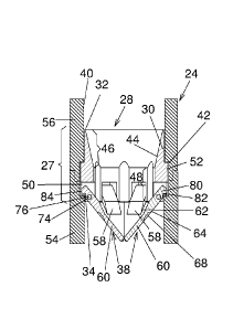
borehole defining a borehole proximal end and an opposed borehole distal end,
the system comprising: an outer tube, the outer tube defining an outer tube
distal end and a flow controller receiving section spaced apart from the outer
tube distal end, the outer tube being configured for attaching the drill bit
thereto
at the outer tube distal end; a flow controller, the flow controller including
a flow
controller body defining a body proximal end and an opposed body distal end,
the flow controller body being securable to the outer tube in the flow
controller
receiving section, the body distal end being closer to the outer tube distal
end
than the body proximal end when the flow controller body is secured to the
outer tube in an operational configuration; and a drilling accessory
insertable in
the outer tube and through the flow controller. The flow controller is movable
between an open configuration and a closed configuration, wherein, when the
flow controller body is secured to the outer tube in the operational
configuration, in the open configuration, the flow controller allows passage
of
the drilling accessory therethrough, and in the closed configuration, the flow
controller hinders flow of the fluid therethrough towards the borehole
proximal
end when the flow controller is located closer to the borehole proximal end
than
the fluid.
[007] In some embodiments of the invention, the flow controller is configured
for
automatically moving from the open configuration to the closed configuration
CA 02900751 2015-08-10
WO 2014/141157
PCT/IB2014/059762
3
when the fluid moves through the flow controller towards the borehole proximal
end and the drilling accessory is withdrawn from the flow controller.
[008] In some embodiments of the invention, the flow controller is configured
for
automatically moving from the closed configuration to the open configuration
when the drilling accessory is moved therethrough in a direction leading from
the body proximal end towards the body distal end.
[009] In a variant, the flow controller further includes at least two pivoting
members, the pivoting members being each pivotally mounted to the flow
controller body so as to be movable between an extended position and a
retracted position, the pivoting members being in the extended position when
the flow controller is in the closed configuration and the pivoting members
being in the retracted position when flow controller is in the open
configuration.
[0010] In some embodiments of the invention, the pivoting members are
substantially parallel to the outer tube.
[0011] In some embodiments of the invention, the flow controller body defines
a
body passageway extending longitudinally therethrough, the pivoting members
extending across the body passageway in the extended position and the
pivoting members being retracted from the body passageway in the retracted
position.
[0012] In some embodiments of the invention, defines a tapered section located
closer to the body proximal end than the pivoting members, the tapered section
tapering in a direction leading towards the body distal end. Also, the body
passageway defines a substantially cylindrical section located closer to the
body distal end than the tapered section.
CA 02900751 2015-08-10
WO 2014/141157
PCT/IB2014/059762
4
[0013] In some embodiments of the invention, in the extended position, the
pivoting members together form a substantially conical structure tapering in a
direction leading from the body proximal end towards the body distal end.
[0014] In some embodiments of the invention, the pivoting members define
each a mounting portion and a flow obstructing portion extending therefrom,
the
mounting portions being pivotally mounted to the flow controller body. For
example, the flow obstructing portion is substantially triangular.
[0015] In some embodiments of the invention, the flow obstructing portion
defines a flow obstructing portion inner surface and an opposed flow
obstructing portion outer surface, the flow obstructing portion outer surface
facing the outer tube distal end when the flow controller is mounted to the
outer
tube in the operational configuration and the flow controller is in the closed
configuration, the flow obstructing portion outer surface defining a groove
extending therealong. For example, the groove is substantially V-shaped and
oriented so as to point towards the body proximal end.
[0016] In some embodiments of the invention, the flow obstructing portions of
all of the pivoting members mate together in the closed configuration so as to
define elongated channels at their junctions.
[0017]In some embodiments of the invention, the flow controller body is
substantially annular and defines at least two substantially circumferentially
extending mounting recesses extending thereinto from the body distal end, the
mounting recesses each receiving at least part of one of the mounting portions
thereinto. For example, the mounting portions each define a mounting aperture
extending thereacross, the flow controller further comprising at least two
mounting pins each extending across a respective one of the mounting
CA 02900751 2015-08-10
WO 2014/141157
PCT/IB2014/059762
recesses substantially circumferentially relative to the flow controller body,
each
of the mounting pins also extending through a respective one of the mounting
apertures so that each of the mounting portions is pivotable relative to the
flow
controller body. In a specific example, the mounting pins are selectively
removable from the flow controller body to allow removal of the pivoting
members therefrom. In some embodiments of the invention, the mounting
portions each define an outer tube engaging portion, the outer tube engaging
portion engaging the outer tube when the flow controller is mounted to the
outer
tube in an operational configuration and the flow controller is in the closed
configuration. For example, the outer tube engaging portion defines a notch
for
receiving part of the outer tube thereinto.
[0018] In some embodiments of the invention, the flow obstructing portions are
located distally relative to the body distal end.
[0019] In some embodiments of the invention, the at least two pivoting
members consist of six pivoting members.
[0020] In some embodiments of the invention, the at least two pivoting
members are freely pivotable between the extended and retracted positions.
[0021] In some embodiments of the invention, the outer tube defines an outer
tube passageway extending therethrough and a substantially annular recess
extending substantially radially outwardly in the outer tube from the outer
tube
passageway in the flow controller receiving section, the flow controller body
defining a substantially annular ridge extending substantially radially
outwardly
therefrom and insertable in the recess.
[0022] In some embodiments of the invention, the recess and the ridge have
CA 02900751 2015-08-10
WO 2014/141157
PCT/IB2014/059762
6
substantially complementary shapes and dimensions so that the ridge is
substantially snugly receivable in the recess.
[0023] In a variant, the drilling accessory includes a sample retrieving
accessory for retrieving a sample from the borehole. For example, the sample
retrieving accessory includes a core barrel assembly.
[0024] In another variant, the drilling accessory includes an instrument for
acquiring data characterizing the subterranean formation or the borehole.
[0025] In some embodiments of the invention, the flow controller includes a
section having a configuration and dimensions similar to those of the drilling
accessory so that when the drilling accessory extends through the flow
controller with the flow controller in the open configuration, the drilling
accessory inhibits passage of the fluid therethrough.
[0026] In another broad aspect, the invention provides a flow controller
usable
with an outer tube and a drilling accessory, the outer tube defining an outer
tube distal end and a flow controller receiving section spaced apart from the
outer tube distal end, the outer tube being configured for attaching a drill
bit
thereto at the outer tube distal end, the flow controller being usable in a
subterranean formation containing a fluid, the flow controller comprising: a
flow
controller body defining a body proximal end and an opposed body distal end,
the flow controller body being securable to the outer tube in the flow
controller
receiving section, the body distal end being closer to the outer tube distal
end
than the body proximal end when the flow controller body is secured to the
outer tube in an operational configuration; the flow controller being movable
between an open configuration and a closed configuration, wherein, when the
flow controller body is secured to the outer tube in the operational
CA 02900751 2015-08-10
WO 2014/141157
PCT/IB2014/059762
7
configuration, in the open configuration, the flow controller allows passage
of
the drilling accessory therethrough, and in the closed configuration, the flow
controller hinders flow of the fluid therethrough towards the borehole
proximal
end when the flow controller is located closer to the borehole proximal end
than
the fluid.
[0027] All the various features of the flow controller part of the system
described
hereinabove are applicable to the flow controller of this aspect of the
invention.
[0028] In yet another broad aspect, the invention provides a method for
retrieving a sample using a sample retrieving accessory from a borehole in a
subterranean formation containing fluids, the borehole defining a borehole
proximal end and an opposed borehole distal end, the borehole being drilled
using a drill bit secured at a tube distal end of an outer tube, the method
using
a flow controller movable between an open configuration and a closed
configuration, the flow controller being mounted in the outer tube, the method
comprising: inserting the outer tube in the borehole such that the flow
controller
is located closer to the borehole proximal end than the fluid; inserting the
sample retrieving accessory in the outer tube and through the flow controller,
the flow controller achieving the open configuration when the sample
retrieving
accessory is inserted therethrough; collecting the sample using the sample
retrieving accessory; withdrawing the sample retrieving accessory from the
borehole; moving the flow controller to the closed configuration when the
sample retrieving accessory is withdrawn at a location closer to the borehole
proximal end than the flow controller, wherein in the closed configuration the
flow controller inhibits flow therethrough of the fluid located distally
relative
thereto.
[0029] In some embodiments of the invention, the flow controller automatically
moves to the closed configuration through the action of the fluid when the
fluid
CA 02900751 2015-08-10
WO 2014/141157
PCT/IB2014/059762
8
flows therethrough.
[0030] In some embodiments of the invention, part of the sample retrieving
accessory remains in the flow controller while the sample is collected to
maintain the flow controller in the open configuration.
[0031] For example, the system and flow controller described hereinabove are
usable to perform the method
[0032] Advantageously, the proposed system provides a relatively easy,
inexpensive and safe manner of reducing overflow of fluids from boreholes
while allowing access to the distal parts of the borehole. Also, the proposed
system greatly reduces risks that a high pressure fluid flow would forcefully
push out of the borehole the drilling accessory, which could present great
danger to drilling personnel. In addition, when the drilling accessory is
lowered
in a borehole using a wireline, such forceful expulsion from the borehole
could
cause problems with the wireline, such as knotting. These problems are
therefore avoided, or at least greatly reduced, with the proposed system.
[0033] Other objects, advantages and features of the present invention will
become more apparent upon reading of the following non-restrictive description
of preferred embodiments thereof, given by way of example only with reference
to the accompanying drawings.
BRIEF DESCRIPTION OF THE DRAWINGS
[0034] In the appended drawings:
[0035] Figure 1, in a schematic view, illustrates and system in accordance
with
an embodiment of the present invention, the system being used for drilling a
CA 02900751 2015-08-10
WO 2014/141157
PCT/IB2014/059762
9
borehole in a subterranean formation containing a fluid;
[0036] Figure 2, in a partial side cross-sectional view, illustrates the
system
shown in Fig. 1;
[0037] Figure 3, in a side elevation view, illustrates a flow controller part
of the
system shown in Figs. 1 and 2, the flow controller being shown in an open
configuration;
[0038] Figure 4, in a side elevation view, illustrates the flow controller
shown in
Fig. 3, the flow controller being shown in a closed configuration;
[0039] Figure 5, in a front cross-sectional view along section line V-V of
Fig. 3,
illustrates the flow controller shown in Figs. 3 and 4, the flow controller
being
shown in the open configuration;
[0040] Figure 6, in a front cross-sectional view along section line VI-VI of
Fig. 4,
illustrates the flow controller shown in Figs. 3 to 5, the flow controller
being
shown in the closed configuration;
[0041] Figure 7, in a bottom plan view, illustrates the flow controller shown
in
Figs. 3 to 6, the flow controller being shown in the open configuration; and
[0042] Figure 8, in a bottom plan view, illustrates the flow controller shown
in
Figs. 3 to 7, the flow controller being shown in the closed configuration.
DETAILED DESCRIPTION
CA 02900751 2015-08-10
WO 2014/141157
PCT/IB2014/059762
[0043] Referring to Fig. 1, there is shown a schematic view of a system 10 in
accordance with an embodiment of the present invention, the system 10 being
usable with a drill bit 12 for drilling a borehole 14 in a subterranean
formation
16 containing a fluid 18. The borehole 14 defines a borehole proximal end 20
and an opposed borehole distal end 22. The system 10 includes an outer tube
24, a flow controller 28 and a drilling accessory 36. The system 10 is
typically
used with machinery (not shown in the drawings) to handle the outer tube 24
and to rotate the outer tube 24 while drilling.
[0044] The outer tube 24 defines an outer tube distal end 26 and a flow
controller receiving section 27 spaced apart from the outer tube distal end
26.
The outer tube 24 is configured for attaching the drill bit 12 to the outer
tube
distal end 26 in a conventional manner. For the purpose of this document, the
terminology proximal and distal refers to a distance from an operator (not
shown in the drawings) outside of the borehole 14 who operates the system 10
to drill the borehole 14. Distal elements are provided further away from the
operator than proximal elements. This terminology is used to facilitate the
description of the system 10 and should not be used to restrict the scope of
the
present invention. Also, the terminology "substantially" in this document is
used
to denote variations in the thus qualified terms that have no significant
effect on
the principle of operation of the system 10. These variations may be minor
variations in design or variations due to mechanical tolerances in
manufacturing and use of the system 10. These variations are to be seen with
the eye of the reader skilled in the art.
[0045] The drilling accessory 36 is insertable in the outer tube 24 and
through
the flow controller 28. An example of a drilling accessory 36 includes a
sample
retrieving accessory for retrieving a sample from the borehole 14. For
example,
such a sample retrieving accessory can include a core barrel assembly. In
another example, the drilling accessory 36 includes an instrument for
acquiring
CA 02900751 2015-08-10
WO 2014/141157
PCT/IB2014/059762
11
data characterizing the subterranean formation 16 or the borehole 14. These
examples of drilling accessories 36 should not be construed as limiting and
any
other suitable drilling accessories 36 are usable.
[0046] Referring for example to Fig. 2, the flow controller 28 includes a flow
controller body 30 defining a body proximal end 32 and an opposed body distal
end 34. The flow controller body 30 is securable to the outer tube 24 in the
flow
controller receiving section 27. The body distal end 34 is closer to the outer
tube distal end 26 (not seen in Fig. 2) than the body proximal end 32 when the
flow controller body 30 is secured to the outer tube 24 in an operational
configuration, such as seen in Fig. 1.
[0047] The flow controller 28 is movable between an open configuration (seen
in Figs. 3, 5 and 7) and a closed configuration (seen in Figs. 2, 4, 6 and 8).
When the flow controller body 30 is secured to the outer tube 24 in the
operational configuration, in the open configuration, the flow controller 28
allows passage of the drilling accessory 36 therethrough. In the closed
configuration, the flow controller 28 hinders flow of the fluid 18
therethrough
towards the borehole proximal end 20 when the flow controller 28 is located
closer to the borehole proximal end 20 than the fluid 18. It should be noted
that
in some embodiments, the flow controller 28 only reduces the flow of the fluid
18 in the closed configuration as compared to the open configuration. For
example, and non-limitingly, the flow controller 28 reduces the flow of fluid
by a
factor of 5 or a factor of 10 when moving from the open configuration to the
closed configuration. However, in some embodiments, the flow controller 28 is
substantially fluid proof in the closed configuration and completely, or
almost
completely, reduces the flow of fluid 18 in the closed configuration.
[0048] Referring to Fig. 2, the outer tube 24 is similar to a conventional
outer
tube 24 used in drilling operations and defines an outer tube passageway 40
CA 02900751 2015-08-10
WO 2014/141157
PCT/IB2014/059762
12
extending therethrough. The outer tube 24 is typically made out of many pipes
screwed to each other and is used to rotate the drill bit 12 to drill the
borehole
14. However, in opposition to conventional outer tubes which are typically of
constant diameter along their whole length, the outer tube 24 defines a
substantially annular recess 42 extending substantially radially outwardly
thereinto from the outer tube passageway 40 in the flow controller receiving
section 27. The recess 42 is used to receive part of the flow controller 28 as
described in further details hereinbelow.
[0049] Typically, the flow controller 28 is configured for automatically
moving
from the open configuration to the closed configuration when the fluid 18
moves
therethrough towards the borehole proximal end 20 and the drilling accessory
36 is withdrawn from the flow controller 28. Also typically, the flow
controller 28
is configured for automatically moving from the closed configuration to the
open
configuration when the drilling accessory 36 is moved therethrough in a
direction leading from the body proximal end 32 towards the body distal end
34.
A non-limiting example of a flow controller 28 that can achieve these
operational characteristics is described hereinbelow. However, in alternative
embodiments of the invention, the drilling accessory 36 and the flow
controller
28 are configured such that the drilling accessory 36 moves the flow
controller
28 to the closed configuration when the drilling accessory 36 is withdraw from
the flow controller 28.
[0050] Referring for example to Figs. 5 and 6, the flow controller body 30
defines a body passageway 44 extending longitudinally therethrough. In
addition to the flow controller body 30, the flow controller 28 further
includes at
least two pivoting members 38, the pivoting members 38 being each pivotally
mounted to the flow controller body 30 so as to be movable between an
extended position and a retracted position. The pivoting members 38 are in the
extended position when the flow controller 28 is in the closed configuration
and
CA 02900751 2015-08-10
WO 2014/141157
PCT/IB2014/059762
13
the pivoting members 38 are in the retracted position when flow controller 28
is
in the open configuration. Any suitable number of pivoting members 38 can be
used, but a flow controller 28 including six pivoting members 38 is well
suited
for many typical drilling operations.
[0051] The pivoting members 38 extend across the body passageway 44 in the
extended position and the pivoting members 38 are retracted from the body
passageway 44 in the retracted position. Typically, in the retracted position,
the
pivoting members 38 are substantially parallel to the outer tube 24 and in the
extended position, the pivoting members 38 together form a substantially
conical structure tapering in a direction leading from the body proximal end
32
towards the body distal end 34. Typically, but not necessarily, the pivoting
members 38 are freely pivotable between the extended and retracted positions,
in other words, there is no element biasing the pivoting members 38 towards
any of the extended and retracted positions. However, in alternative
embodiments of the invention not shown in the drawings, springs or other
suitable biasing elements may bias the pivoting members 38 towards one of
the extended and retracted positions.
[0052] Referring for example to Fig. 5, the body passageway 44 defines a
tapered section 46 located closer to the body proximal end 32 than the
pivoting
members 38. Typically, the tapered section 46 extends from the body proximal
end 32. The tapered section 46 tapers in a direction leading towards the body
distal end 34 and guides the drilling accessory 36 as the drilling accessory
enters the body passageway 44. For example, the tapered section 46 is
substantially frusto-conical. The body passageway 44 also defines a
substantially cylindrical section 48 located closer to the body distal end 34
than
the tapered section 46. Typically, the cylindrical section 48 extends from the
tapered section 46 and reaches the body distal end 34. Typically, the
cylindrical
section 48 and the drilling accessory 36 have substantially similar
transversal
CA 02900751 2015-08-10
WO 2014/141157
PCT/IB2014/059762
14
cross-sectional configurations and dimensions so that the drilling accessory
36
is substantially tightly fitted in the cylindrical section 48. This tight fit
prevents a
large flow of the fluid 18 through the flow controller 28 when the drilling
accessory 36 is inserted therethrough.
[0053] The flow controller body 30 is substantially annular and defines at
least
two substantially circumferentially extending mounting recesses 50 extending
thereinto from the body distal end 34, one for each pivoting member 38. Also,
the flow controller body 30 defines a substantially annular ridge 52 extending
substantially radially outwardly therefrom and insertable in the recess 42 of
the
outer tube 24. Typically, the recess 42 and the ridge 52 have substantially
complementary shapes and dimensions so that the ridge 52 is substantially
snugly receivable in the recess 42. In some embodiments of the invention, as
seen in Fig. 2, the outer tube 24 can be separated into two outer tube
sections
54 and 56 removably attachable to each other, for example using threads (not
shown in the drawings), and each defining part of the recess 42. This allows
easy assembly of the flow controller 28 and outer tube 24 in a rigid and
sturdy
configuration.
[0054] Referring for example to Fig. 5 and 6, in some embodiments of the
invention the pivoting members 38 define each a mounting portion 58, which is
for example substantially elongated, and a flow obstructing portion 60
extending therefrom. The mounting portions 58 is pivotally mounted to the flow
controller body 30. The flow obstructing portions 60 typically abut against
each
other in the closed configuration, as seen in Figs. 4, 6 and 8.
[0055] Returning to Figs. 5 and 6, in some embodiments of the invention, the
flow obstructing portion 60 is substantially triangular. The flow obstructing
portion 60 may be substantially flat, or may include a slight curve so as to
better approximate a cone when abutting against each other in the closed
CA 02900751 2015-08-10
WO 2014/141157
PCT/IB2014/059762
configuration.
[0056] The flow obstructing portions 60 each define a flow obstructing portion
inner surface 62 and an opposed flow obstructing portion outer surface 64. The
flow obstructing portion outer surface 64 faces the outer tube distal end 26
when the flow controller 28 is mounted to the outer tube 24 in an operational
configuration and the flow controller 28 is in the closed configuration. As
better
seen in Figs. 3, 4 and 8, in some embodiments of the invention, the flow
obstructing portion outer surface 64 defines a groove 66 extending therealong.
For example, the groove 66 is substantially V-shaped, oriented so as to point
towards the body proximal end 32, and entirely located distally relative to
the
location on the pivoting member 38 about which the pivoting member 38 pivots.
The groove 66 helps configuration of the flow controller 28 from the open
configuration to the closed configuration when the fluid 18 moves through the
flow controller 28 by creating a moment of force on the pivoting member 38. In
some embodiments of the invention, as better seen in Fig. 3, the flow
obstructing portion 60 also defines beveled edge portions 68 adjacent the
mounting portions 58 for the same purpose.
[0057] In some embodiments of the invention, the flow obstructing portions 60
of all of the pivoting members 38 mate together in the closed configuration so
as to define elongated channels 72 at their junctions, as better seen in Fig.
8.
The channels 72 help in maintaining the flow controller 28 in the closed
configuration 28 under pressure from the fluid 28. Also, in some embodiments
of the invention, the flow obstructing portions 60 are outside of the flow
controller body 30, distal relative to the body distal end 34. Also,
typically, the
flow obstructing portions 60 are substantially adjacent to the body distal end
34
in the closed configuration.
[0058] Referring now to Fig. 5, the mounting portions 58 each define a
CA 02900751 2015-08-10
WO 2014/141157
PCT/IB2014/059762
16
mounting aperture 74 extending thereacross. The mounting recesses 50 each
receive at least part of one of the mounting portions 58 thereinto, more
specifically part of the mounting portions 58 including the mounting aperture
74.
A mounting pin 76 extends across each of the mounting recesses 50
substantially circumferentially relative to the flow controller body 30. Each
of the
mounting pins 76 also extends through a respective one of the mounting
apertures 74 so that each of the mounting portions 58 is pivotable relative to
the flow controller body 30.
[0059] In some embodiments of the invention, the mounting pins 76 are
selectively removable from the flow controller body 30 to allow removal of the
pivoting members 38 therefrom. To that effect, as seen in Figs. 3 and 4, pin
access apertures 78 extend through the flow controller body 30 to axially
reach
the mounting pins 76. For example, the mounting pins 76 are press-fitted to
one of the pin access apertures 78 or the mounting apertures 74 and freely
pivotable relative to the other one of the pin access apertures 78 and the
mounting apertures 74. However, in alternative embodiments of the invention,
the mounting portions 58 are pivotally mounted to the flow controller body 30
in
any other suitable manner.
[0060] In some embodiments of the invention, the mounting portions 58 each
define an outer tube engaging portion 80. The outer tube engaging portion 80
is
provided opposed to the flow obstructing portions 60 and engages the outer
tube 24 when the flow controller 28 is mounted to the outer tube 24 in an
operational configuration and the flow controller 28 is in the closed
configuration, as seen in Fig. 2. The outer tube engaging portion 80 prevents
over rotation of the pivoting members 38 in the extended position as the
pivoting members 38 have to resist the pressure exerted by the fluid 18. To
that
effect, the outer tube engaging portion 80 may for example define a notch 82
for receiving part of the outer tube 24 thereinto, for example for receiving
the
CA 02900751 2015-08-10
WO 2014/141157
PCT/IB2014/059762
17
part of the outer tube 24 just distal to the recess 42. In addition, the outer
tube
engaging portion 80 may define an abutment surface 84 adjacent the notch 80
for abutting against the outer tube 24 in the extended position.
[0061] The flow controller 28 may be manufactured using any suitable material
capable of withstanding the environment in which the system 10 operates, such
as, for example and non-limitingly, stainless steel.
[0062] In use, the flow controller 28 allows drilling personnel to perform a
method for retrieving a sample (not shown in the drawings) using the drilling
accessory 36 in the form of a sample retrieving accessory from a borehole 14
in a subterranean formation 16 containing fluid 18.
[0063] First, the flow controller 28 is mounted in the outer tube 24. The flow
controller 28 may be used for most of the drilling operation, or the flow
controller 28 may be used when previous surveys or other indications (such a a
rise in the amount of fluid contained in the borehole 14) indicates that the
subterranean formation 16 including the fluid 18 will be reached soon. The
outer tube 24 is inserted in the borehole 14 such that the flow controller 28
is
located closer to the borehole proximal end 20 than the fluid 18. Drilling can
then continue until the fluid 18 containing subterranean formation 16 is
reached.
[0064] When the fluid 18 is reached, the flow controller 28 rapidly assumes
the
closed configuration, which prevents a large outflow of the fluid 18. A small
quantity of fluid 18 may be allowed to leak in some embodiments as such small
quantities of fluids 18 are easily managed and will be under less pressure
than
the fluid 18 distal to the flow controller 28 due to the restriction to fluid
18 flow
provided by the flow controller 28.
CA 02900751 2015-08-10
WO 2014/141157
PCT/IB2014/059762
18
[0065] When the drilling personnel wishes to retrieve a sample from the
borehole 14, the sample retrieving accessory is inserted in the outer tube 24
and through the flow controller 28. The flow controller 28 achieves the open
configuration when the sample retrieving accessory is inserted therethrough.
In
some embodiments, the open configuration is achieved due to the weight of the
sample retrieving accessory as the sample retrieving accessory is lowered
through the flow controller 28. In other embodiments, the sample retrieving
accessory is pushed through the flow controller 28 to achieve the open
configuration. Typically, part of the sample retrieving accessory remains in
the
flow controller 28 while the sample is collected to maintain the flow
controller 28
in the open configuration to minimize fluid 18 flow therethrough.
[0066] Then, the sample is collected in a conventional manner using the sample
retrieving accessory. For example, if the sample retrieving accessory is a
core
barrel assembly, drilling continues while a core is retrieved by the core
barrel
assembly.
[0067] Afterward, the sample retrieving accessory is withdrawn from the
borehole 14 and the flow controller 28 is moved to the closed configuration
when the sample retrieving accessory is withdrawn to a location closer to the
borehole proximal end 20 than the flow controller 28. Typically, the flow
controller 28 automatically moves to the closed configuration through the
action
of the fluid 18 when the fluid 18 flows therethrough.
[0068] Once all sample retrieving operations from the region containing the
fluid
18 have been completed, conventional manners of fluid proofing the borehole
14 may be applied so that the flow controller 28 is no longer required.
[0069] As mentioned hereinabove, other operations, such as borehole
19
surveying or subterranean formation characterizing may also be performed in a
similar manner using the flow controller 28 and a suitable drilling accessory
36.
[0070] Although the present invention has been described hereinabove by way
of exemplary embodiments thereof, it will be readily appreciated that many
modifications are possible in the exemplary embodiments without materially
departing from the novel teachings and advantages of this invention.
Accordingly, the scope of the claims should not be limited by the exemplary
embodiments, but should be given the broadest interpretation consistent with
the description as a whole.
CA 2900751 2020-01-09