Note: Descriptions are shown in the official language in which they were submitted.
CA 02900846 2015-08-11
WO 2014/135306
PCT/EP2014/051513
-1-
Gyratory Crusher Spider Arm Shield
15
Field of invention
The present invention relates to a gyratory crusher spider arm shield and in
particular,
although not exclusively, to a shield configured for the convenient mounting
and
dismounting at the spider arm so as to protect the arm from material to be
crushed as it
falls into the crushing zone.
Background art
Gyratory crushers are used for crushing ore, mineral and rock material to
smaller sizes.
Typically, the crusher comprises a crushing head (referred to as a mantle)
mounted upon
an elongate main shaft. A first crushing shell is mounted on the crushing head
and a
second crushing shell is mounted on a frame such that the first and second
crushing shells
define together a crushing chamber through which the material to be crushed is
passed. A
driving device positioned at a lower region of the main shaft is configured to
rotate an
eccentric assembly positioned about the shaft to cause the crushing head to
perform a
CA 02900846 2015-08-11
WO 2014/135306 PCT/EP2014/051513
-2-
gyratory pendulum movement and crush the material introduced in the crushing
chamber.
Example gyratory crushers are described in WO 2004/110626; WO 2008/140375, WO
2010/123431, US 2009/0008489, GB 1570015, US 6,536,693, JP 2004-136252, US
1,791,584 and WO 2012/005651.
The main shaft is supported at its uppermost end by a top bearing housed
within a central
hub that forms a part of a spider assembly mounted on top of the topshell
frame part.
Spider arms project radially outward from the central hub to contact an outer
rim at the top
shell. The material to be crushed typically falls through the region between
the spider arms
and is prevented from causing damage to the arms by shields mounted over and
about each
arm. Example shields are disclosed in US 2,489,936; US 2,832,547; US
3,026,051; US
2002/0088888; US 2011/0192927. It is noted, these shields are typically
secured to the
spider arm via attachment bolts that project axially downward relative to the
longitudinal
axis of the main shaft. However, such configurations are disadvantageous as
the bolt heads
are exposed to the crushable material as it falls into the crushing chamber.
With use, the
bolt heads become damaged leading to attachment failure and subsequent loss of
the shield
that falls downwardly into the crushing chamber.
An alternative method of shield attachment involves welding the guards to the
uppermost
region of the spider arms. However, the welding process is both labour and
time intensive
and introduces additional problems when the worn shield needs removing.
Additionally,
the welding creates tension and stress concentrations into the spider arms.
What is
required is a spider arm shield that addresses the above problems.
Summary of the Invention
It is an objective of the present invention to provide a shield or guard for a
spider arm that
may be conveniently attached and dismounted from the spider assembly without
compromising the physical and mechanical integrity of the arm. It is a further
objective to
minimise, as far as possible, the time required to attach and remove the
shield at the spider
assembly whilst also minimising the number of personnel needed for attachment
and
dismantling.
CA 02900846 2015-08-11
WO 2014/135306 PCT/EP2014/051513
-3-
It is a further objective to provide a releasable spider guard in which the
mechanical
attachments are positioned so as to be shielded from the falling crushable
material to
prevent attachment failure and undesired exposure of the arm and damage to the
crusher.
The objectives are achieved by providing a multiple-point attachment mechanism
that
functions to draw the shield both radially inward towards the central hub and
axially
downward onto the upper region of the arm. In particular, attachment elements
extend
radially inward from a radially outermost region of the guard to journal the
guard radially
inward towards the central hub. A mount guide formed at a lower region of the
shield acts
to pull the shield axially downward onto the arm as the attachment elements
are actuated.
The mount guide also serves to prevent upward axial separation of the shield
from the arm.
According to a first aspect of the present invention there is provided a
gyratory crusher
spider arm shield for releasable attachment to a spider arm that extends
radially outward
from a central hub and forms a part of a spider assembly positioned on a
topshell frame of
a gyratory crusher, the shield comprising: a main body having an underside
foot for
positioning on top of the spider arm, a first end for positioning at or
towards the central
hub and a second end for positioning at a region radially outward from the
hub; a pair of
sidewalls extending downwardly from the main body at each lengthwise side of
the
underside foot; characterised by: at least one attachment element extending
radially inward
from a region of the second end in a direction substantially towards the first
end so as to be
capable of engaging radially into the spider arm to journal the shield
radially inward
towards the hub; and a mount guide provided respectively at each sidewall to
engage
respective side regions of the spider arm and configured to guide the mating
contact
between the shield and the arm.
In particular, the mount guide is configured to journal the shield in an
axially downward
direction onto the arm. Preferably, each mount guide comprises a recess
extending
inwardly within each sidewall from an edge region of each sidewall. More
preferably,
each recess is orientated in each sidewall such that at least a region of each
recess is angled
upwardly in a direction from a lowermost edge at the respective sidewall
towards the foot.
CA 02900846 2015-08-11
WO 2014/135306 PCT/EP2014/051513
-4-
Advantageously, a lowermost edge of the recess is angled upwardly in a
direction from a
lowermost edge of each sidewall towards the foot. In particular, the lowermost
edge of the
recess provides an inclined abutment region that contacts the corresponding
mount element
projecting laterally from each side of the spider arm. Accordingly, each
recess provides a
set of jaws configured to engage around (at least partially) each laterally
extending mount
element (preferably in the form of a short lug).
Optionally, the attachment element comprises at least one bolt extending
through the main
body substantially from the second end. Preferably, the shield further
comprises at least
one depression at the second end to at least partially accommodate a head of a
respective
bolt. Preferably, the shield comprises two depressions in a form of cavity-
like recesses
extending radially inward from the radially outermost end region of the
shield.
Preferably, the shield comprises a plurality of projections extending
downwardly from the
foot to engage onto a top region of the arm. Preferably, at least one
projection is
positioned towards the first end and at least one projection is positioned
towards the second
end of the main body.
According to a second aspect of the present invention there is provided a
spider assembly
for a gyratory crusher comprising: a central hub; a plurality of spider arms
extending
radially outward from the hub towards an outer rim; a plurality of arm shields
releasably
attached to the respective arms, each shield comprising: a main body having an
underside
foot for positioning on top of the spider arm, a first end for positioning at
or towards the
central hub of the spider assembly and a second end for positioning at a
region radially
outward from the hub; a pair of sidewalls extending downwardly from the main
body at
each lengthwise side of the underside foot; characterised in that: each shield
comprises a
mount guide provided at each respective sidewall and each spider arm comprises
respective mount elements to engage with the respective mount guide and
configured to
guide the mating contact between the shield and the arm; and at least one
attachment
element to engage into a respective spider arm and to mate the respective
mount elements
and the mount guides to releasably secure the shield at the spider arm.
CA 02900846 2015-08-11
WO 2014/135306 PCT/EP2014/051513
-5-
Preferably, the mount guide and the mount elements are configured to journal
the shield in
an axial downward direction onto the arm when mated together.
Preferably, each mount guide comprises a recess extending inwardly within each
sidewall
from an edge region of each sidewall. Preferably, each mount element comprises
a lug
projecting laterally from one side of the spider arm at a region between the
hub and the
outer rim.
Preferably, each arm comprises a pair of lugs, each lug projecting laterally
from each side
of the arm. Preferably the lugs are aligned concentrically and parallel with
one another
and extend substantially perpendicular to the main length of the spider arm
that projects
radially outward from the central hub. Preferably, a size of the recess is
configured to at
least partially receive the lug to inhibit upward axial movement of the shield
relative to the
arm when each lug is mated into each recess.
Optionally, the attachment element comprises at least one bolt extending
through the main
body substantially from the second end.
According to a third aspect of the present invention there is provided a
gyratory crusher
comprising: a topshell mounted upon a bottom shell and defining an internal
crushing
chamber; a main shaft supporting a mantle capable of gyroscopic precession
within the
crushing chamber; and a spider assembly and spider arm shields as detailed
herein.
Brief description of drawings
A specific implementation of the present invention will now be described, by
way of
example only, and with reference to the accompanying drawings in which:
Figure 1 is a cross sectional side view of a gyratory crusher having an upper
frame part, a
lower frame part and rotatable main shaft and a spider assembly mounted at the
upper
frame part to support and stabilise the main shaft according to a specific
implementation of
the present invention;
CA 02900846 2015-08-11
WO 2014/135306 PCT/EP2014/051513
-6-
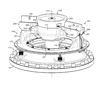
Figure 2a is a perspective view of the spider assembly of figure 1 with arm
shields secured
in position over each respective spider arm according to a specific
implementation of the
present invention;
Figure 2b is an external side elevation view of the arm shields and spider of
figure 2a;
Figure 2c is a plan view of the arm shields and spider of figure 2a and 2b;
Figure 3 is a magnified perspective view of one of the arm shields of figure
2a;
Figure 4 is a side elevation cross section through one arm shield and spider
arm of figure
2b;
Figure 5a is a perspective underside view of the shield of figure 4;
Figure 5b is a perspective topside view of the shield of figure 5a;
Figure Sc is a plan view of the shield of figure 5a;
Figure 5d is an end elevation view of the shield of figure 5a from a radially
innermost end;
Figure 5e is an end elevation view of the shield of figure 5a from a radially
outermost end.
Detailed description of preferred embodiment of the invention
Referring to figure 1, a crusher comprises a frame 100 having an upper frame
101 and a
lower frame 102. A crushing head 103 is mounted upon an elongate shaft 107. A
first
(inner) crushing shell 105 is fixably mounted on crushing head 103 and a
second (outer)
crushing shell 106 is fixably mounted at upper frame 101. A crushing zone 104
is formed
between the opposed crushing shells 105, 106. A discharge zone 109 is
positioned
immediately below crushing zone 104 and is defined, in part, by lower frame
102.
CA 02900846 2015-08-11
WO 2014/135306 PCT/EP2014/051513
-7-
A drive (not shown) is coupled to main shaft 107 via a drive shaft 108 and
suitable gearing
116 so as to rotate shaft 107 eccentrically about longitudinal axis 115 and to
cause head
103 to perform a gyratory pendulum movement and crush material introduced into
crushing chamber 104. An upper end region of shaft 107 is maintained in an
axially
rotatable position by a top-end bearing assembly 112 positioned intermediate
between
main shaft 107 and a central boss 117. Similarly, a bottom end 118 of shaft
107 is
supported by a bottom-end bearing assembly 119.
Upper frame 101 is divided into a topshell 111, mounted upon lower frame 102
(alternatively termed a bottom shell), and a spider assembly 114 that extends
from topshell
111 and represents an upper portion of the crusher. The spider 114 comprises
two
diametrically opposed arms 110 that extend radially outward (in direction B)
from a central
boss 117 positioned on a longitudinal axis 115 extending through frame 100 and
the
gyratory crusher generally (indirection A). Arms 110 are attached to an upper
region of
topshell 111 via an intermediate annular flange (or rim) 113 that is centred
around
longitudinal axis 115. Typically, arms 110 and topshell 111 form a unitary
structure and
are formed integrally. A cap 123 extends over an upper region of shaft 107 and
central
boss 117 so as to protect the working components 112 at the upper region of
the crusher.
In order to protect the spider arms 110 from the crushable material that falls
downwardly
into the topshell 111, an arm shield 120 is mated onto and around each arm
110. Each
shield 120 comprises a main body 121 that is configured to sit on top of arm
110 and a pair
of sidewalls 122 that extend downwardly over each side of arm 110.
Referring to figures 2a to 5e, each arm comprises a generally radially
extending section
200 (aligned substantially with direction B) and a generally axially extending
section 201
that projecting substantially downward (in direction A) from a radially
outermost end of
section 200. Arm section 201 terminates at an upper surface of rim 113. A
shoulder 405 is
located at the junction between section 200 and section 201.
The main body 121 of each shield is generally elongate and has a first end 205
and a
second end 206. In use, first end 205 is configured for positioning against or
towards
CA 02900846 2015-08-11
WO 2014/135306 PCT/EP2014/051513
-8-
central hub 117 and/or an outer circumferential surface 209 of central cap
123. An
outermost second end 206 of shield 120 is positioned above the radially
outermost region
of arm section 201. Accordingly, a length of main body 121 between ends 205
and 206 is
approximately equal to a length of region 200 in direction B.
Referring to figures 3 to 5a, main body 121 comprises an underside surface
region 400 for
positioning directly over an uppermost surface region 311 of arm section 200.
A first pair
of cylindrical feet 401 project downwardly from surface 400 to contact arm
surface 311 at
a radial position towards central hub 117. A second pair of cylindrical feet
402 also extend
from surface 400 to contact surface 311 towards the radially outermost part of
arm section
200. That is, feet 401 are positioned towards first end 205 and feet 402 are
positioned
towards radially outermost second end 206. Feet 401, 402 rest on top of
surface 311 to
create a small gap between shield surface 400 and arm surface 311. A pair of
parallel
sidewalls 122 project downward from the lengthwise edges of main body 121.
Each
sidewall 122 terminates at a lowermost edge 303 that is aligned substantially
at a mid-
thickness region of arm section 200 in the axial direction A. Edge 303
terminates at its
radially innermost region by edge 406 that tappers upwardly to return to main
body 121
towards first end 205. An opposed radially outermost region of edge 303
terminates at
edge 408 that tappers upwardly to second end 206 of main body 121. Each
sidewall 122
comprises an opposed inward facing surface 500 configured for positioning
opposed and
against the opposed side surfaces 307 of arm section 200. In particular, wall
surfaces 500
extend substantially perpendicular to foot surface 400 and sidewalls 122
extend
approximately two thirds of the length of shield 120 between first and second
ends 205,
206. Accordingly, the upper surface 311 and side surfaces 307 of arm section
200 are
shrouded by shield 120 and in particular downward facing surface 400 and the
opposed
lateral side surfaces 500.
A recess 202 is formed in each wall 122 and extends inwardly from edge 406.
Recess 202
comprises an innermost part circular section 306 that is connected to upper
part of edge
406 by a substantially straight edge section 305. Edge 305 is aligned
substantially parallel
with the orientation of main body 121 and surfaces 400, 311. A lowermost part
of curved
edge 306 straightens into a lower edge region 304 that is inclined upwardly
relative to the
CA 02900846 2015-08-11
WO 2014/135306 PCT/EP2014/051513
-9-
horizontal and surfaces 311, 400. Accordingly, recess 202 is formed as a short
slot having
at least a region that projects at an upward inclined angle within wall 122.
In the radial
direction B, recess 202 is positioned between radially innermost feet 401 and
radially
outermost feet 402 and in particular, at a position radially closer to feet
401 than feet 402.
Main body 121 comprises a radially outermost wall 502 that extends laterally
between
sidewalls 122 at second end 206. Wall 402 also projects downwardly from
surface 400. A
pair of slots 501 extend upwardly within wall 502 at end 206. Arm shoulder 405
is formed
just below a radially outermost region of surface 311 and comprises a pair of
threaded bore
holes 404 orientated radially inward in direction B. Each slot 501 extends
within a
respective recessed depression region 208 formed in a radially outermost part
of wall 502.
Each depression 208, being a cavity-like region, is sized sufficiently to
accommodate a
head 207 an elongating bolt having at least a part threaded shaft 403. When
guard 120 is
secured to arm 110, each shaft 403 (of a pair of parallel bolts) is
respectively inserted
through slots 501 to engage into arm bores 404 at shoulder 405. Accordingly,
shield 120 is
journalled radially into central hub 117 as each bolt is tightened into bore
404. A radial
depth of each depression 208 is configured such that each bolt head 207 does
not protrude
radially outward beyond a surface 302 at second end 206. Positioning the bolts
in this
radial orientation and accommodating heads 207 within depressions 208 is
advantageous to
prevent damage to the bolts by the crushable material falling downwardly onto
shields 120.
Each arm 110 comprises a relatively short cylindrical lug 203 that projects
laterally
outward from each side surface 307 of each arm section 200. Each lug 203 is
positioned
slightly above the mid-point of arm section 200 in the axial direction A. A
diameter of
each lug 203 is slightly less than a diameter or width of recess 202 such that
lug 203 is
capable of being received within recess 202. When fully inserted in position,
the curved
outer cylindrical surface of lug 203 is mated against the arcuate innermost
edge 306 of
recess 202. In the fully mated configuration of figures 1 to 4, shield 120 is
prevented from
displacement in axial direction A by mating of each lug 203 within each recess
202 and the
attachment of shield 120 at arm 110 via the pair of bolts 207, 403 extending
radially
inward from second end 206.
CA 02900846 2015-08-11
WO 2014/135306 PCT/EP2014/051513
-10-
A channel 407 extends lengthwise along main body 121 and is recessed upwardly
in
surface 400. As illustrated in figures 4 and 5a, channel 407 is configured to
accommodate
lubrication tubing 311 that extends around an upper region of arm 110.
Main body 121 comprises three upwardly projecting flanges 300, 301. Flanges
300, 301
extend the full length of arm shield 120 between first and second ends 205,
206. Flange
300 extends axially upward from a mid-region of main body 121 and is aligned
approximately centrally over arm 110. A pair of side flanges 301 are
positioned directly
above walls 122 and project radially upward in direction A from the end
lengthwise edges
of main body 121. A distance by which central flange 300 extends from main
body 121 is
approximately twice the corresponding height of side flanges 301. Accordingly,
a pair of
parallel elongate channels 309 is defined by flanges 300, 301. In use,
channels 309 are
configured to collect crushable material as it falls downwardly onto each
shield 120. An
aperture 204 extends through a mid-point of flange 300 to receive a hook or
engaging end
of lifting apparatus used to remove each shield 120 axially upward for
maintenance and
repair.
A width of each shield 120 in the lateral direction over arm region 200
decreases via a pair
of opposed curved regions 308 located radially between recess 202 and first
end 205. Each
curved region 308 effectively terminates the radially innermost end of each
sidewall 122
such that the radially innermost region of each shield 120 is located
exclusively above arm
section 200 towards first end 205.
To attach each shield 120 to a respective arm 110, the feet 401, 402 are mated
onto arm
surface 311 such that sidewalls 122 project laterally downward over arm
section 200 with
surfaces 500 and 307 being opposed. Shaft 403 of each attachment bolt is
inserted through
slots 501 to engage into arm the respective shoulder bore 404. As each bolt
207, 403 is
screwed into shoulder 405 and the entire shield 120 is journalled radially
inward in
direction B. Additionally, due to the shape, configuration and relative
position of each
recess 202, shield 120 is also journalled axially downward in direction A,
principally due
to the inclined edge 304 that mates and abuts against the outer surface of lug
203. As bolts
207, 403 are tightened, lug 203 is mated into recess 202. Accordingly, each
shield 120 is
CA 02900846 2015-08-11
WO 2014/135306
PCT/EP2014/051513
-11-
secured to arm 110 via a plurality of points of contact including in
particular contact
between: feet 401 and 402 and surface 311; lug 203 and recess 202 and; bolt
shafts 403
and shoulder 405.
Due to the positioning of each recess 202 in a radial direction relative to
feet 401, 402 the
entire shield 120 is prevented from rotation. Also, a secure attachment is
achieved by the
radially inward orientation of attachment bolts 207, 403 that serves to
journal mating
contact between the laterally extending arm lugs 203 and each guard recess
207.