Note: Descriptions are shown in the official language in which they were submitted.
MALE LUER CONNECTOR WITH VALVE HAVING FLUID PATH
AND VENT PATH SEALS
Cross-references to related applications
[0001] Not applicable.
BACKGROUND
Field
[0002] The present disclosure generally relates to needleless connectors, and,
in particular, to
self-sealing male needleless connectors.
Description of the Related Art
[0003] Medical treatments often include the infusion of a medical fluid, for
example a saline
solution or a liquid medication, to patients using an intravenous (IV)
catheter that is connected
though an arrangement of flexible tubing and fittings, commonly referred to as
an "IV set," to a
source of fluid, for example an IV bag. Needleless fittings commonly include
male and female
needleless connectors having a "Luer taper" conforming to an International
Standards
Organization (ISO) standard wherein mating of Luer fittings forms a liquid-
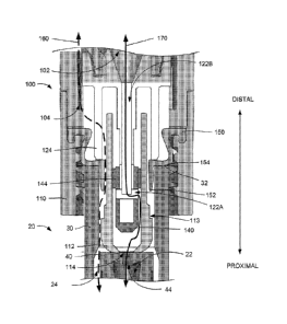
tight connection.
[0004] Certain connectors have a self-sealing feature to prevent leakage of
fluid from the
attached tubing when the connector is decoupled from a mating connector.
Typical self-sealing
needleless connectors provide only a fluid path and, therefore, provide a self-
sealing capability
only for the fluid path.
SUMMARY
[0005] The needleless male connector disclosed herein provides both a fluid
path and a vent
path, each having a self-sealing feature wherein connection of the disclosed
male connector to a
compatible female connector opens both the fluid and vent paths and
disconnection closes both
paths.
1
CA 2900999 2020-03-04
[0006] In certain embodiments, there is described a male needleless connector
comprising: a
body having a male fitting with a port; a valve disposed within the body and
having a first
position wherein the valve seals the port and a second position wherein the
valve does not seal
the port; and a sliding seal disposed over a portion of the male fitting and
having a first
configuration wherein a first portion of the sliding seal is in sealing
contact with the male
fitting to seal a vent path and a second configuration wherein the first
portion is not in sealing
contact with the male fitting, wherein moving the sliding seal to the second
configuration opens
the seal between the sliding seal and the male fitting to open the vent path
and displaces the
valve to the second position, thereby opening the seal between the valve and
the port.
[0007] In certain embodiments, there is further described a needleless
connector comprising:
a body comprising a fluid path, a vent path, and a male fitting; a valve
disposed within the male
fitting; and a seal coupled to the body and slidingly disposed over a portion
of the male fitting,
wherein the valve and seal respectively block the fluid and vent paths when
the connector is in
an unconnected configuration, and wherein the fluid and vent paths are open
when the
connector is in a connected configuration.
[0007a] In certain embodiments, there is further described a needleless
connector comprising:
a body comprising a fluid path, a vent path, and a male fitting; a valve
disposed within the male
fitting and configured to move between a first configuration, in which the
fluid path is blocked,
and a second configuration, in which the fluid path is open; and a seal
fixedly disposed around
the valve and configured to slide along an inner surface of the male fitting
and to separate the
fluid path from the vent path in the first configuration and in the second
configuration.
10007b1 In certain embodiments, there is further described a male needleless
connector
comprising: a body having a male fitting with a port; a valve disposed within
the body and at
least partially within the male fitting, the valve comprising a lateral fluid
passage open to an
interior of the male fitting and a longitudinal fluid passage connected to the
lateral fluid
passage; a sliding seal configured to be in sealing contact with the male
fitting in a first
configuration and not be in sealing contact with the male fitting in a second
configuration; and
a vent path, wherein the vent path is closed in the first configuration and
open in the second
configuration.
2
Date Recue/Date Received 2020-07-08
[0007c] In certain embodiments, there is further described a needleless
connector set,
comprising: a male connector comprising: a body comprising a fluid path, a
vent path, and a
male fitting; a valve disposed within the male fitting and configured to move
between a first
configuration, in which the fluid path is blocked, and a second configuration,
in which the fluid
path is open; and a seal fixedly disposed around the valve and configured to
slide along an
inner surface of the male fitting and to separate the fluid path from the vent
path in the first
configuration and in the second configuration; a female connector comprising:
a body; and a
collapsible valve disposed within the body; wherein the male connector and the
female
connector are in the first configuration when not mated and in the second
configuration when
mated.
[0007d] In certain embodiments, there is further described a needleless
connector comprising: a
body having a male fitting and a port; a valve disposed within the body, the
body and the valve
defining a vent path and a fluid path; a sealing tip disposed over a portion
of the valve; and a
sliding seal disposed over a portion of the male fitting, wherein the sealing
tip and the sliding
seal are configured to block the vent and fluid paths in a first valve
position and to open the vent
and fluid paths in a second valve position.
BRIEF DESCRIPTION OF THE DRAWINGS
[0008] The accompanying drawings, which are included to provide further
understanding and
are incorporated in and constitute a part of this specification, illustrate
disclosed
2a
Date Recue/Date Received 2020-07-08
CA 02900999 2015-08-11
WO 2014/163850
PCT/US2014/018078
embodiments and together with the description serve to explain the principles
of the disclosed
embodiments. In the drawings:
100091 FIGS. IA- IC are cross-sections of a conventional needleless male
connector.
100101 FIGS. 2A-2B are cross-sections of an exemplary male needleless
connector and a
compatible female connector according to certain aspects of the present
disclosure.
100111 FIG. 3 is a cross-section depicting the male and female connectors of
FIGS. 2A-2B in
an engaged configuration according to certain aspects of the present
disclosure.
DETAILED DESCRIPTION
100121 The needleless male connector disclosed herein provides both a fluid
path and a vent
path, each having a self-sealing feature wherein connection of the disclosed
male connector
to a compatible female connector opens both the fluid and vent paths and
disconnection
closes both paths.
100131 In the following detailed description, numerous specific details are
set forth to provide
a full understanding of the present disclosure. It will be apparent, however,
to one ordinarily
skilled in the art that embodiments of the present disclosure may be practiced
without some
of the specific details. In other instances, well-known structures and
techniques have not
been shown in detail so as not to obscure the disclosure. In the referenced
drawings, like
numbered elements are the same or essentially similar. Reference numbers may
have letter
suffixes appended to indicate separate instances of a common element while
being referred to
generically by the same number without a suffix letter.
100141 FIGS. IA-IC are cross-sections of a conventional needleless male
connector 4 as
disclosed in U.S. Patent 8,182,452. FIG. IA depicts the male connector 4 and a
compatible
female connector 2 prior to being mated. The connector 4 has a male fitting 5
with a port 7
on the tip. An internal valve 6 slides relative to the fitting 5 and is biased
toward the
proximal direction such that the tip of the valve 6 seals the port 7 when the
male connector 4
is not mated with female connector 2.
100151 FIGS. 1B and IC are cross-sections taken on perpendicular planes
through the mated
connectors 2 and 4. In this configuration, the face 3 of the female connector
2 has contacted
posts 8 that are connected to the valve 6 and displaced the posts 8, and
therefore the valve 6,
3
CA 02900999 2015-08-11
WO 2014/163850
PCT/LIS2014/018078
in a distal direction. This motion displaces the tip of valve 6 from the port
7, thereby
allowing fluid to flow through the mated connectors 2 and 4 along the flow
path 9.
100161 It can be seen from the FIGS. IA-IC that there is no gas flow path
through the
connectors 2 and 4, nor is there a closable vent path to the ambient
atmosphere of any
gas-filled portion of the male connector 4. This is typical of conventional
fluid needleless
connectors in that they are generally intended for connecting fluid lines, for
example the fluid
lines of a medical intravenous (IV) set.
[0017] FIGS. 2A-2B are cross-sections of an exemplary male needleless
connector 100 and a
compatible female connector 20 according to certain aspects of the present
disclosure. The
male needleless connector 100 shown in FIG. 2A has a body 110 with a male Luer
fitting 112
with a port 114 at a proximal end of the fitting 112. In certain embodiments,
the male
fitting 112 does not have a later taper. A valve 120 is slidably disposed
within the body 110
and partially within the male fitting 112. A sealing tip 140 is disposed over
a proximal
tip 124 of the valve 120. The valve 120 is biased in the proximal direction by
the action of an
accordion bellows 130 disposed within cavity 104 distal to the valve 120 such
that the sealing
tip 140 sealingly contacts the port 114 of the male fitting 112. In this
configuration, the
external surface 142 of the sealing tip 140 is approximately flush with the
external surface of
the male fitting 112 around the port 114. The sealing tip 140 includes a
second seal 144 that
forms a sliding seal between the valve 120 and the male fitting 112.
[0018] A passage 122 passes through the valve 120 and the sealing tip 140 and
comprises, in
this example, a longitudinal fluid passage I 22B that passes from the open
internal cavity 102
of the bellows 130 to a lateral fluid passage 122A that is open to the
interior of the male
fitting 112. The internal cavity 102 connects to a fluid passage of an
attached fluid line or
fitting (not shown in FIG. 2A).
[0019] The valve 120 has a plurality of fingers 124 that extend toward the
proximal end of
the valve 120. In this example, there are four fingers 124 while, in other
embodiments, there
may be fewer or greater than four fingers 124.
[0020] A sliding seal 150 is disposed over a portion of the male fitting 112
and the
fingers 1.24 with a tip 152 of the sliding seal 150 in sealing contact with a
recess 113 in the
male fitting 112. A distal end of the sliding seal 150 is captured, in this
example, between
two components that form the body 110. The sliding seal 150 also has a
shoulder 154
4
CA 02900999 2015-08-11
WO 2014/163850
PCT/US2014/018078
disposed proximate to the proximal tips of the fingers 124. In certain
embodiments, the
sliding seal comprises an elastomeric material. In certain embodiments, the
sliding seal
comprises a flexible material.
[0021] FIG. 2B illustrates certain features of a compatible female Fitting 20
that, in this
example, is a female Luer fitting that is compatible with the example male
Luer fitting of
FIG. 2A. In certain embodiments, the connector 20 does not have a Luer taper.
The
connector 20 has a body 30 with a distal surface 32 and an opening 34. A
collapsible
valve 40 is disposed within the body 30 and has a distal end 42 that, in this
configuration, is
disposed within the opening 34 such that the distal face 46 is approximately
flush with the
distal surface 32 of the body 30. The tip 42 comprises a slit 44 that is
forced closed when the
tip 42 is positioned as shown in FIG. 2B and will self-open when the
collapsible valve 40 is
displaced in a proximal direction such that the tip 42 is displaced into the
wider cavity 24 of
the body 30. The slit 44 passes from the distal face 46 into the internal
passage 22 that
connects to a fluid passage of an attached fluid line or fitting (not shown in
FIG. 2B).
[0022] FIG. 3 is a cross-section depicting the male and female connectors 100,
20 of
FIGS. 2A-2B in an engaged configuration according to certain aspects of the
present
disclosure. The body 30 of the female connector 20 has been threaded into the
body 110 of
the male fitting 112 such that the connectors 100, 20 are retained in the
engaged
configuration. As the body 30 was threaded into the body 110, the distal
surface 32 of the
body 30 came into contact with the shoulder 154 of the sliding seal 150 and,
as the body 30
advanced into the body 110, displaced the shoulder 154 and the adjacent
Fingers 124 in a
distal direction. As the distal end of the sliding seal 150 is captured by the
body 110, the
displacement of the shoulder 154 collapses the sliding seal 150 generally as
shown, as an
example, in FIG. 3. The displacement of the shoulder 154 also draws the tip
152 of the
sliding seal 150 away from the recess 113, thereby opening a vent path 160
from the cavity
104 between the sliding seal 150 and the male fitting 114 into the internal
cavity 24, indicated
in FIG. 3 by the dashed line labeled "160."
[0023] The distal displacement of the finger 124 causes the entire valve 120
to move in the
distal direction, thereby distally displacing the second scal 144 within the
male fining 112
and the sealing tip 140 from the port 114. At the same time, the male fitting
112 displaced
the collapsible valve 40 such that the slit 44 self-opened. As the second seal
144 maintains
the seal between the valve 120 and male fitting 112, a fluid path 170 is now
provided from
CA 02900999 2015-08-11
WO 2014/163850
PCT/US2014/018078
the internal cavity 102 through the mated connectors 100, 20 to the internal
passage 22, as
indicated by the solid line labeled "170." It can be seen that the fluid path
170 and the vent
path 160 are separated by seals between the male fitting 112 and the
collapsible valve 40,
between the second seal 144 of the sealing tip 140 and the male fitting 112,
and between the
accordion bellows 130 and the valve 120. In certain embodiments, the vent path
160 may
open before the fluid path 170. In other embodiments, the fluid path 170 may
open before
the vent path 160. In other embodiments, the fluid path 170 and the vent path
160 may open
at approximately the same time.
100241 In certain embodiments, the sliding seal 150 may form a sealing contact
with the male
fitting 112 in locations other than tip 152. In certain embodiments, the
recess 113 may be
absent and the tip 152 seals against a smooth external surface of the male
fitting 112. In
certain embodiments, the male fitting 112 may have external features (not
shown), for
example ridges running in a distal-proximal direction, that expand, as the
sliding seal is
displaced, a portion of the sliding seal 150 that sealingly contacts the
fitting 112 when in an
undisplaced configuration.
100251 In summary, it can be seen that the disclosed embodiments of the
needleless
connector provide a fluid path and a vent path that are each sealed when the
male and female
connectors are not mated and are opened automatically as the connectors are
mated.
[00261 The previous description is provided to enable any person skilled in
the art to practice
the various aspects described herein. While the foregoing has described what
are considered
to be the best mode and/or other examples, it is understood that various
modifications to these
aspects will he readily apparent to those skilled in the art, and the generic
principles defined
herein may be applied to other aspects. Thus, the claims are not intended to
be limited to the
aspects shown herein, but is to be accorded the full scope consistent with the
language
claims, wherein reference to an element in the singular is not intended to
mean "one and only
one" unless specifically so stated, but rather "one or more." Unless
specifically stated
otherwise, the terms "a set" and "some" refer to one or more. Pronouns in the
masculine
(e.g., his) include the feminine and neuter gender (e.g., her and its) and
vice versa. Headings
and subheadings, if any, are used for convenience only and do not limit the
invention.
[0027] It is understood that the specific order or hierarchy of steps in the
processes disclosed
is an illustration of exemplary approaches. Based upon design preferences, it
is understood
that the specific order or hierarchy of steps in the processes may be
rearranged. Some of the
6
CA 02900999 2015-08-11
WO 2014/163850
PCT/US2014/018078
steps may be performed simultaneously. The accompanying method claims present
elements
of the various steps in a sample order, and are not meant to be limited to the
specific order or
hierarchy presented.
[0028] Terms such as "top," "bottom," "front," "rear" and the like as used in
this disclosure
should be understood as referring to an arbitrary frame of reference, rather
than to the
ordinary gravitational frame of reference. Thus, a top surface, a bottom
surface, a front
surface, and a rear surface may extend upwardly, downwardly, diagonally, or
horizontally ill
a gravitational frame of reference.
[0029] A phrase such as an "aspect" does not imply that such aspect is
essential to the subject
technology or that such aspect applies to all configurations of the subject
technology. A
disclosure relating to an aspect may apply to all configurations, or one or
more
configurations. A phrase such as an aspect may refer to one or more aspects
and vice versa.
A phrase such as an "embodiment" does not imply that such embodiment is
essential to the
subject technology or that such embodiment applies to all configurations of
the subject
technology. A disclosure relating to an embodiment may apply to all
embodiments, or one or
more embodiments. A phrase such an embodiment may refer to one or more
embodiments
and vice versa.
100301 The term "exemplary" is used herein to mean "serving as an example or
illustration."
Any aspect or design described herein as "exemplary" is not necessarily to be
construed as
preferred or advantageous over other aspects or designs.
100311 The terms "include," "have," "with," and the like are intended to be
inclusive in a
manner similar to the term "comprise" as "comprise" is interpreted when
employed as a
transitional word in a claim.
[00321 No claim element is to be construed under the provisions of 35 U.S.C.
112, sixth
paragraph, unless the element is expressly recited using the phrase "means
for" or, in the case
of a method claim, the element is recited using the phrase "step for."
100331 All structural and functional equivalents to the elements of the
various aspects
described throughout this disclosure that are known or later come to be known
to those of
ordinary skill in the art are expressly incorporated herein by reference and
are intended to be
7
CA 02900999 2015-08-11
WO 2014/163850
PCT/US2014/018078
encompassed by the claims. Moreover, nothing disclosed herein is intended to
be dedicated
to the public regardless of whether such disclosure is explicitly recited in
the claims.
8