Note: Descriptions are shown in the official language in which they were submitted.
i
CA 02901100 2015-08-12
1
SYSTEM AND METHOD FOR SCANNING A SURFACE AND COMPUTER PROGRAM
IMPLEMENTING THE METHOD
Field of the Art
The present invention relates generally, in a first aspect, to a system for
scanning a
surface, comprising means for illuminating different regions of a surface to
be scanned and
means for receiving and detecting the portions of light reflected on same
including one or
more light detectors, and more particularly to a system which allows using the
total spatial
resolution of the light detector or detectors for each of the regions of the
surface to be
scanned.
A second aspect of the invention relates to a method suitable for performing
the
functions carried out by the system of the first aspect.
A third aspect of the invention relates to a computer program implementing the
method of the second aspect.
Background of the invention
TOF (acronym of "Time Of Flight"), LIDAR (acronym of "Light detection and
ranging")
or LADAR (acronym of "Laser detection and ranging") measurement systems are
systems
which allow measuring distances by means of using a light source illuminating
the points
being measured.
The measurable distance in TOF systems is influenced by some uncontrolled
factors
which depend on the environment and not on the TOF technique, such as for
example, the
background illumination intensity, the weather conditions (fog, dust, rain,
etc.) or the
reflectance of the object.
In addition, there are other aspects that depend directly on the technology
and the
architecture of the TOF device and play a main role in the determination of
the measurable
distance of each system. Among said aspects, the most significant aspects
could be the
illumination source power, light beam divergence, point scanning system
efficiency,
photodetector sensitivity, optical system attenuation or background light
filtering quality.
The physical principles of TOF, LIDAR or LADAR systems state that, expressed
in a
very general manner, the capability of measuring a point located at a certain
distance is
related to the capability of illuminating it with sufficient optical power to
detect the light beam
reflected thereon in a light detector. This principle has a decisive influence
on the
õ
2
measurable distance of the device and different scanning techniques have been
designed
based on same in order to take measurements of TOF images. There are TOF
devices
which can measure distances up to dozens of kilometers and others are limited
to a few
meters. The illuminating beam in far-reaching systems usually has little
divergence. These
.. tend to use highly collimated laser light beams with a very small
divergence and beam
section. With this, the energy concentration per unit of surface in the object
is much greater if
compared with systems using diverging light sources. Systems using diverging
light sources
illuminate larger areas for simultaneously measuring a set of points instead
of only one.
To take measurements of three-dimensional image by means of TOF, LIDAR or
LADAR techniques, it is necessary to measure a set of points forming a three-
dimensional
image (or point cloud) and to that end, it is necessary to illuminate the
surface corresponding
to the image to be measured. The technologies which allow measuring a set of
points in a
controlled manner for forming three-dimensional images are basically divided
into two:
- Sequential scanning systems.
- Systems based on arrays of detectors.
The sequential scanning systems form the 3D image by sequentially measuring
unique points. The illumination sequence is usually implemented by means of
optical
systems such as galvanometric mirrors, MEMS, acoustic optical deflectors,
etc... Given a
specific optical power, the sequential scanning systems concentrate said power
at a small
point measuring greater distances in comparison with beam-expanding systems.
The
collimation and the small size of the illuminated point mean that energy
concentration per
unit of surface is higher than in the case of diverging light sources. This
high energy
concentration per unit of surface means that the light reflected by the object
is greater and as
a result, the detector receiving the light from that point also receives a
larger amount of light.
Taking into account that one of the main factors that sets the limitation in
the capability of
measuring in distance in LIDAR systems is the capability of detecting low
power reflected
optical beams, the effect of energy concentration of the sequential scanning
systems
successfully maximizes the measurable distance as a result of harnessing all
the optical
power available for a single point of measurement. The greater the energy
concentration per
unit of surface, more energy flow is reflected on the point of measurement and
accordingly,
the easier the detection is. Although the sequential scanning systems allow
obtaining a high
spatial resolution in the three-dimensional image, performing point-to-point
measurement
means that the total measurement time is high in order to attain images having
a high spatial
Date Recue/Date Received 2020-09-02
3
resolution. This limits the amount of images which can be measured per second.
By way of
example, commercial equipment based on this technology such as RieglTM laser
scanners
(http://www.rieql.com/), MDLTm laser scanners (http://www.mdl-laser.com) or
FaroTM laser
scanners (http://www.faro.com), can be mentioned.
In addition, there are systems based on arrays of detectors. These systems use
a set
of detectors arranged in grid in which each of them has the TOF measuring
capability, based
on pulsed TOF, TOF-FMCW or TOF-"Range Gated". In these systems, the points of
the
three-dimensional image are measured simultaneously through a set of
detectors. In other
words, said detectors measure in a synchronized manner a set of distance
values equivalent
to the number of detectors of the array and, at the same time, that set of
measured points
forms a three-dimensional image. The main advantage of these systems lies in
the fact that
several measurements are performed simultaneously which allows measuring a
complete
image through a single TOF measuring action. For example, in the case of
pulsed TOF, a
complete three-dimensional image can be measured through a single laser pulse
(nevertheless, some equipment use more than one pulse to increase the quality
of the image
through successive measurement integration).
A condition necessary for performing simultaneous measurements through an
array
of detectors (partially or completely, i.e., using the entire array or only a
part thereof) involves
simultaneously illuminating all those points in the object which will be
measured by the group
of detectors. This means that the optical power is divided among all the
points. Therefore,
given an illumination source having a specific energy, the energy
concentration per unit of
surface will be distributed among all the points of measurement causing the
energy reflected
by each individual point to be inversely proportional to the number of
measured points. By
way of example, the "Flash LADAR" systems of the company Advanced Scientific
Concepts TM (http://www.advancedscientificconcepts.com/), the pulsed TOF
cameras of Odos
Imaging TM (http://odos-imaqinq.com/), as well as most TOF cameras based on
TOF-FMCW
(Time-of-Flight Frequency Modulated Continuous Waveform) measurement, for
example,
cameras from Mesa ImagingTM (www.mesa-imaqinq.ch), PMDTm (www.omdtec.com) or
SoftKineticTM (http://www.softkinetic.com), can be mentioned.
The main advantage of this system with respect to the sequential scanning
systems
lies in the fact that the points are measured in parallel successfully
measuring a large
number of points for each TOF measuring action. In contrast, the sequential
scanning
systems perform a single measurement per TOF measuring action. Generally, it
can be
Date Recue/Date Received 2020-09-02
4
stated that considering an illumination source having determined power and
shared between
the two systems, the amount of three-dimensional images measured will be
greater for the
systems based on arrays of detectors than in the sequential measurement
systems as a
result of the effect of parallel measurements. Nevertheless, given that the
illumination energy
is finite and, in this comparative case, the same between the two systems, the
measured
distance will be greater in the sequential scanning system than in the of
array of detectors
given that the energy used for the point of measurement will be greater
because all the
power of the source is concentrated on one and the same point of measurement.
At an intermediate point, there are pieces of equipment which are made up of
sets of
detectors performing measurements simultaneously and sequential scanning at
the same
time. This technique is usually used for measuring larger surfaces. By way of
example, the
system of the company Velodyne LidarTM (http://velodvnelidar.com) can be
highlighted. This
system performs simultaneous measurements through a set of detectors while at
the same
time a rotary mechanical head performs scanning circularly in a 3600 angle to
attain a circular
field of view. It can be considered that such systems bring together the
characteristics of the
two general methods described above since they are capable of measuring a set
of points
simultaneously while at the same time performing sequential scanning to
measure all the
points forming the final three-dimensional image.
In most systems based on array of detectors, the spatial resolution of the
three-
dimensional image is fixed by the number of detectors of the array of
detectors.
Nevertheless, there is a system which allows obtaining a spatial resolution in
the image
greater than that of the array of detectors. Said TOF system is described in
the international
patent application W02012123809A1, and allows increasing the spatial
resolution of the
three-dimensional image as a result of the inclusion and use of light switches
arranged in
grid or an array of light switches (such as a light spatial modulator based on
micromirrors,
such as the case of a DMD: Digital Micromirror Device), in a number greater
than light
detectors, sequentially redirecting towards the array of light detectors the
different portions of
light reflected on the surface to be scanned. The inventors refer to that
technology as "Digital
Scanning" and it is considered to be located in an intermediate level between
systems based
on array of detectors and sequential scanning as it implements the two
methods.
Nevertheless, said scanning is digitally controlled and moving parts are not
involved in same.
One of the uses of the system described in international patent application
W02012123809A1 is the measurement of three-dimensional images by means of the
TOF
Date Recue/Date Received 2020-09-02
CA 02901100 2015-08-12
or time of flight technique. A light source illuminates the surface to be
measured. The DMD
receives said beam through an optical group and sequentially redirects the
received beam
towards a detector or an array of detectors having TOF measuring capability.
Given that the
DMD is optically conjugated with the object being measured, it is capable of
receiving in a
5 controlled manner the light from each point of measurement. Each light
switch is conjugated
with a point of the surface to be measured, therefore, each light switch is
capable of directing
said portion of the total beam to the detector system or of rejecting same.
Given that the
DMD or array of switches and the detector or array of detectors are optically
conjugated, the
DMD is capable of directing said portions of the beam, which at the same time
correspond to
the light reflected by the points of the object to be measured, to the set of
detectors in a
controlled manner. Through a sequential process, the DMD will receive and
direct the light
reflected on the object towards the detector or group of detectors such that,
the DMD will
simultaneously send as many portions of the beam as the number of detectors
present in
said array of TOF detectors. In other words, a number of simultaneous TOF
measurements
equivalent to the number of detectors will be performed. The sequential
measurement
process consists of directing in a controlled manner all the points of the
surface which the
DMD is optically configured to receive. The resulting three-dimensional image
will have as
many measured points as the number of light switches in the DMD. Considering
that the
DMD has a much larger number of light switches than the array of detectors,
the resulting
image will have a spatial resolution greater than the number of detectors.
This characteristic
means that through a small group of detectors, and in turn less complex
technically and more
cost-effective than one with a large amount of detectors, TOF images having a
high spatial
resolution and with added functionalities can be measured.
One of the characteristics of this system is that for each TOF measuring
action it is
necessary to illuminate the entire surface to be measured. The entire surface
is understood
as the entire set of points which will form the three-dimensional image
resulting from
performing the sequential measurement process. Like what occurs in the systems
based on
arrays of detectors described above, this system illuminates the entire
surface to be scanned
causing the optical power available to be distributed among all the points of
the surface in
each TOF measuring action and only a small group of points (equivalent to the
number of
detectors) will be measured. The larger the number of detectors in the array
of detectors, the
more illumination energy is harnessed given that the number of simultaneously
measured
points is greater and the number of rejected points is lower. This has an
impact on the light
CA 02901100 2015-08-12
6
energy received in each point of the surface and, accordingly, negatively
affects the distance
of detection given that the illumination energy is divided among all the
points of the surface.
The TOE three-dimensional image measurement systems have several applications
and markets in which these systems are of use. Only by way of example, an
application of
interest for which it would be of interest to use such systems belongs to the
field of
automotive industry, particularly systems for monitoring, detecting and
recognizing objects in
the environment of an automobile in order to obtain information about the
space in which this
automobile circulates for purposes of safety, navigation or artificial
intelligence while driving.
For such application, there are various fundamental performance requirements
that
must be met by the system to assure the use thereof in said context. Some of
them are
specified below only by way of example:
¨ Operation in an outdoor environment under conditions with a large amount
of daylight
and background illumination.
¨ Measurable distance up to 100 meters.
¨ Viewing angle: horizontal 200, vertical 50.
¨ Real time image measurement (> 10 Hz).
Considering a distance of 100 m with said viewing angles, the surface to be
measured has about 750 m2. A TOE system based on an array of detectors will
have to
completely illuminate such surface in each TOF measuring action. Taking into
account the
radiometric parameters involved in the illumination, reflection and detection
process of said
beam, also considering the amount of background light and the detector
parameters, it can
be concluded that the illumination energy necessary for being able to be
detected in the
array of detectors is potentially very high. A sequential scanning system
would require less
illumination energy but its performance in terms of measurement speed would
also be
limited, being able to have limitations in moving object measurement.
Additionally, the inverse-square law establishes that the light intensity on a
surface
receiving light from a point light source is inversely proportional to the
square of the distance
between the light source and the surface and proportional to the cosine
between the light
beam and the normal to the surface. This means that the illumination intensity
on a
determined area will decrease with distance according to a quadratic factor.
When a surface
which is illuminated with a light source is moved away from the light source,
the illumination
intensity of the surface decreases, the illumination intensity decreasing much
faster than the
surface is being moved away from the light source. For example, if the
illumination on a
CA 02901100 2015-08-12
7
surface is 40 lux at a distance of 0.5 m from the light source, the
illumination decreases to 10
lux at a distance of 1 m. This phenomenon decisively influences the measurable
distance in
a TOF system. In systems based on arrays of detectors, this effect can be
acceptable for
short distances (10 to 15 m) where the illumination intensity per m2 remains
high, but when
measurement of medium-long distances (more than 15 m) and large areas is
required, this
phenomenon becomes a problem, since the illumination sources have limited
energy.
According to the knowledge of the present inventors, this is a real limiting
factor in terms of
distance measured in systems based on arrays of detectors.
To that end, and based on a series of studies based on simulations of
different
radiometric models performed by the present inventors, it can be said that use
of systems
based on arrays of detectors for applications in the field of automotive
industry, in which
measurements of at least 100 meters are required, is clearly unviable, because
it would
involve using a laser source having enormous power, which are very expensive,
have a high
consumption and are incompatible with the safety rules for eyes. The
aforementioned
commercial TOF cameras work well for certain applications (indoor environments
and for
ranges of short distances) but have serious limitations in outdoor
environments with daylight
and for medium-long distances. It must be noted that most of them use LEDs as
a light
source the power of which is substantially less compared with the laser
sources used in
sequential scanning systems.
The foregoing can be extrapolated to many other fields of application
different from
the field of automotive industry, all of them under the mentioned influence of
the inverse-
square law, although each field of application will have its particular
restrictions relating to
operating environment, measurement distances, viewing angles, etc.
According to the knowledge of the inventors, there is no TOF device today
which
meets the requirements herein described for being applied on a massive scale
in the field of
automotive industry, even meeting the price requirements.
For such application in the field of automotive industry, and for many other
applications of interest, it would be of interest to provide a system
combining the advantages
of the two methods for generating 3D images in TOF, i.e., the advantages of
sequential
scanning and the advantages of the systems based on arrays of detectors. The
objective
thereof would be to perform measurements on objects located at a greater
distance than that
covered by the systems based on arrays of detectors, with a good spatial
resolution, a
CA 02901100 2015-08-12
8
measurement speed greater than the sequential scanning systems and, using
light sources
having less power.
Patent application US20120249999A1 discloses one of such combined systems,
since it proposes combining a "Flash LADAR" system with a laser scanning
system for the
purpose of using lasers with less power if the complete field of view does not
have to be
measured. In this system, the "Flash LADAR" component measures the distance to
the
illuminated object by means of TOF and the scanning system selectively
illuminates said
object. The inventors describe a series of applications such as the detection
and tracking of
stationary and/or moving objects, navigation or collision avoidance systems
always based on
the "Flash LADAR" technology also patented by the same inventors.
By means of the system proposed by patent document US20120249999A1, a laser
light beam is projected on a sub-area (object) to be detected contained within
the field of
view, with a determined divergence so that a simultaneous measurement of said
entire sub-
area, including a single pixel or a small group of pixels, takes place, i.e.,
using a divergence
greater than that of sequential scanning systems and less than that of systems
based on
array of detectors.
To direct the laser towards the sub-area to be scanned, a mirror of a
galvanometric
system (for example, MEM type) is used, so it can be said that the system of
US20120249999A1 is actually a combination of the two TOF systems described
above.
It is indicated that in the system proposed in US20120249999A1, the
illumination
beam can be varied so that it illuminates the field of view of the Flash LADAR
system entirely
(all the pixels of the array of detectors) or only partially (one or more
pixels of the array of
detectors) depending on the application.
In the system of patent document US20120249999A1 detection is performed with
an
array of light detectors the total resolution of which is adapted to the total
area of the surface
or scene to be scanned, so when they illuminate the mentioned sub-area a lower
spatial
resolution is obtained, i.e., if they only illuminate 10% of the total area,
only 10% of the pixels
of the array of light detectors will be illuminated, i.e., will receive
reflected light, so a spatial
resolution of only 10% of the total resolution of the array will be obtained,
which means that
such system provides rather poor results in terms of spatial resolution. In
other words, the
detectors of the array which are optically conjugated with the pixels of the
sub-areas which
are not being illuminated cannot be used for TOF measurement, causing this
underuse of the
set of detectors of the array to negatively affect the spatial resolution of
the TOF image in
9
comparison with the case of using a light source completely illuminating the
field of view of
the array of detectors in which all the detectors are used.
Brief Description of the Invention
It seems to be necessary to offer an alternative to the state of the art which
overcomes the drawbacks found therein, and which particularly provides a
solution to the
problems of the system proposed in patent document US20120249999A1 in terms of
spatial resolution.
To that end, the present invention relates, in a first aspect, to a system for
scanning
a surface, comprising:
- a light source configured to illuminate a surface to be scanned, which is
at least
partially reflective;
- a reception and detection unit configured to receive and detect a portion
of the
light reflected by said surface,
said reception and detection unit comprising a light redirection unit
including a
plurality of light redirection elements arranged according to a determined
spatial distribution
model, in a number greater than the number of some light detectors including
at least one
light detector, and configured to receive portions of reflected light, each of
said portions in at
least one part of a respective sub-model of said determined spatial
distribution model, and
said light redirection unit being configured and arranged to sequentially
redirect each
of the portions of reflected light received in at least said part of each of
said sub-models
towards said at least one light detector,
wherein the system further comprises a light direction device associated with
said
light source configured to direct at least one light beam with a determined
divergence so
that it illuminates different sub-areas of the surface to be scanned in an
alternating manner,
and wherein said reception and detection unit is configured and arranged to
receive and
detect, in an alternating manner, corresponding portions of light of said
light beam reflected
on each of said different sub-areas of the surface to be scanned.
According to one embodiment, the light redirection means are configured and
arranged for receiving each of the portions of reflected light in the entirety
of said respective
sub-model of said determined spatial distribution model, and for sequentially
redirecting
each of the portions of reflected light received in each of said sub-models
towards said at
least one light detector.
CA 2901100 2019-01-30
10
For one embodiment, said determined spatial distribution model forms an array,
and
each of said sub-models forms a sub-array.
According to a variant of said embodiment, said array is a grid and said sub-
array is
a sub-grid or a linear array.
According to a preferred embodiment, the system comprises a plurality of light
detectors, including said light detector, arranged in grid or according to
another type of
spatial distribution model, the light redirection means being configured and
arranged for
sequentially redirecting each of the portions of reflected light received in
each of the sub-
models of the light redirection elements towards the light detectors arranged
in grid or
according to another type of spatial distribution model.
Although most part of the present description refers particularly to the grid
arrangement of the light detectors, for other embodiments, the plurality of
light detectors are
discrete detectors which are not arranged in grid, i.e., they do not form a
uniform grid. The
following description (in this section and subsequent sections) with respect
to the grid of
light detectors is also valid for these embodiments in which they do not form
a uniform grid.
According to one embodiment, the light redirection means further comprise at
least
one reflective element arranged between the determined spatial distribution
model of the
light redirection elements and the light detector or the grid or another type
of light detector
spatial distribution model, which is movable to collaborate with the light
redirection elements
for carrying out said sequential redirection of each of the portions of
reflected light received
in each of the sub-models towards the light detector or light detectors
arranged in grid or
according to another type of spatial distribution model, by means of
performing respective
sequential optical conjugations of the portions of reflected light received in
each of the sub-
models with the light detector or light detectors arranged in grid or
according to another type
of spatial distribution model.
According to an alternative embodiment, the light redirection means comprise
at
least one reflective element (static or that does not need to move) and an
optical system
arranged between the determined spatial distribution model of the light
redirection elements
and the light detector or the grid or another type of light detector spatial
distribution model,
where said optical system is configured and arranged for, the reflective
element remaining
static, optically conjugating at all times the light detector or the grid or
another type of light
detector spatial distribution model with the entire determined spatial
distribution model of
the light redirection elements.
CA 2901100 2019-01-30
11
Alternatively to the embodiment described in the preceding paragraph, i.e.,
the one
referring to the inclusion of a static reflective element or a reflective
element that does not
need to move, according to another embodiment, the light redirection means
does not
comprise any reflective element, including instead an optical element, such as
a lens, or
without including any replacement element.
For one embodiment, the system of the first aspect of the invention comprises
control means of the light redirection elements controlling same for
sequentially activating
the light redirection elements of each sub-model, for carrying out the
sequential redirection
of each of the portions of reflected light received in each of the sub-models
towards the light
detector or light detectors arranged in grid or according to another type of
spatial
distribution model.
For a preferred embodiment, the light direction means are configured for
sequentially directing the light beam.
For the purpose of carrying out the mentioned alternating direction of the
light beam,
the light direction means comprise, according to one embodiment, at least one
reflective
and/or deflective device arranged between the light beam and the surface to be
scanned,
and which is movable for carrying out said alternating direction of the light
beam and/or has
elements capable of carrying out the alternating direction of the light beam
without the
reflective and/or deflective device being moved. For this last case, according
to several
embodiments, the reflective and/or deflective device is an electro-optical
modulator or an
acoustic optical modulator which, as is known, include such elements capable
of carrying
out the alternating direction of the light beam without the entire device
having to be moved
(so the device can be or remain stationary).
For one embodiment, the number of light redirection elements of each of the
sub-
models is equal to the number of light detectors.
In contrast, for another embodiment, in this preferred case as it allows
further
increasing the spatial resolution of the three-dimensional image, the number
of light
redirection elements of each of the sub-models is greater than the number of
light
detectors, and the system comprises control means associated with the light
redirection
means for carrying out the redirection of each of the portions of reflected
light received in
each of the sub-models towards the light detectors, sequentially redirecting
sub-portions of
each portion of reflected light towards the light detector or detectors, by
means of the
independent control of corresponding sub-groups of light redirection elements
of each sub-
model.
CA 2901100 2019-01-30
12
For a more basic embodiment, the reception and detection means comprise only
one light detector, so each sub-model of the light redirection elements
includes, for a first
variant, only one light redirection element redirecting the portion of
reflected light received
towards the only light detector, and, for another more preferred variant, each
sub-model
includes several light redirection elements, each of which sequentially
redirects a
corresponding sub-portion of the portion of reflected light received in the
sub-model towards
the only light detector.
According to one embodiment, the system proposed by the first aspect of the
invention comprises control means associated with the light direction means
and a the light
redirection means for carrying out both the direction of the light beam
towards the different
sub-areas of the surface to be scanned and the redirection of each of the
portions of
reflected light towards the light detector or detectors, in a synchronized
manner.
According to one embodiment, each light redirection element is formed by a
variable
number of light redirection microelements.
For one embodiment, the determined spatial distribution model of the light
redirection elements is a model of light switches, and for other embodiments
the determined
spatial distribution model of the light redirection elements comprises a light
spatial
modulator based on micromirrors, a liquid crystal display or deformable
mirrors.
For a preferred embodiment, the system of the first aspect of the invention is
particularly applicable to performing TOF measurements, therefore it
comprises, in
association with or as part of the reception and detection means, measurement
means for
measuring the distance between the system and each point of the surface to be
scanned by
means of determining the time of flight, an intermediate or hybrid system
between
sequential scanning systems and systems based on arrays of detectors making
use of the
advantages as regards beam concentration of the first systems and taking
parallel
measurements of the second systems, thus being obtained. The spatial
uniformity of the
points of the measured TOE image is assured by the model of the light
redirection elements
or model of light switches which, in a preferred embodiment, is a DMD from
Texas
Instruments or another type of light spatial modulator based on micromirrors.
For other embodiments, the system of the first aspect of the invention is
applied for
performing another type of measurements, such as measurements of light
intensity, color or
photon count.
CA 2901100 2019-01-30
13
The mentioned measurement means are configured for obtaining a three-
dimensional topographic image (point cloud) of the surface to be scanned,
according to one
embodiment.
At least the light redirection elements and/or the mentioned reflective
element and/or
the reflective and/or deflective device are implemented, according to one
embodiment, by
means of microelectromechanical systems (MEMs).
According to one embodiment, the system proposed by the first aspect of the
invention constitutes or forms part of a three-dimensional space measurement
system
which, for a preferred variant is applied in the field of automotive industry
for the detection
and tracking of objects and obstacles, such as other vehicles or pedestrians
and,
advantageously, for automatic or supervised vehicle navigation.
Other applications of interest of the system proposed by the first aspect of
the
invention are those included in the following non-exhaustive list:
¨ Intelligent video surveillance.
¨ Border area control.
¨ Three-dimensional vision in security systems.
¨ Self-guided vehicles.
¨ 3D multimedia video.
¨ Object detection and tracking.
¨ Safety driving assist.
¨ Intelligent transportation systems.
¨ Under foliage detection.
¨ Mapping.
¨ Artificial vision in robotics.
A second aspect of the invention relates to a method for scanning a surface,
which
comprises:
- illuminating a surface to be scanned which is at least partially reflective;
- receiving a portion of reflected light in at least one part of a
respective sub-model
of a determined spatial distribution model in which a plurality of light
redirection elements
are arranged in a number greater than a number of light detectors including at
least one
light detector; and
- sequentially redirecting each portion of portions of reflected light
received in at
least said part of each of said sub-models towards said at least one light
detector of said
light detectors,
CA 2901100 2019-01-30
14
wherein said step of illuminating a surface comprises projecting on said
reflective
surface to be scanned at least one light beam with a determined divergence for
illuminating
a sub-area of the area forming said surface to be scanned, directing said
light beam so that
it illuminates different sub-areas of the surface to be scanned in an
alternating manner; and
wherein the method further comprises receiving and detecting in said at least
one
light detector, in an alternating manner, corresponding portions of light, of
said light beam
reflected on each of said different sub-areas of the surface to be scanned and
redirected
from each one of said sub-models.
For one embodiment, the method comprises receiving each of the portions of
reflected light in the entirety of said respective sub-model of said
determined spatial
distribution model, and sequentially redirecting each of the portions of
reflected light
received in each of said sub-models towards said at least one light detector.
For one embodiment, said determined spatial distribution model forms an array,
and
each of said sub-models forms a sub-array.
According to a variant of said embodiment, said array is a grid and said sub-
array is
a sub-grid, and according to another variant, the array is a grid and the sub-
array is a linear
array.
According to one embodiment, the method proposed by the second aspect of the
invention comprises sequentially redirecting each of the portions of reflected
light received
in each of the sub-models of the light redirection elements towards a
plurality of light
detectors, including said light detector, arranged in grid or according to
another spatial
distribution model.
According to a preferred embodiment, the method proposed by the second aspect
of
the invention comprises carrying out the scanning of the surface to be scanned
using the
system of the first aspect of the invention.
According to another embodiment, the method of the second aspect of the
invention
comprises determining and varying the degree of divergence of the light beam
and/or
varying the number of light redirection elements of each sub-model, in an
automatic manner
and/or under a user's indication and/or according to a series of local input
signals and/or
remote input signals and/or input signals coming from internal and/or external
detectors, to
increase the distance of emission, for the purpose of detecting a surface from
a greater
distance, and/or the scanning speed, sacrificing spatial resolution, or to
increase the spatial
resolution, sacrificing received optical power, for the purpose of scanning an
object of
interest with greater precision.
CA 2901100 2019-01-30
15
According to one embodiment, the method comprises carrying out the variation
of
the degree of divergence of the light beam and/or of the number of light
redirection
elements of each sub-model, on the go, according to the circumstances of the
operation
and/or environment and/or object detections performed.
According to one embodiment, the method of the second aspect of the invention
comprises varying the number of light redirection elements of the sub-model or
sub-models
of the light redirection elements where the light reflected on a detected
object has been
received.
At the same time, the method proposed by the second aspect of the invention
comprises, for one embodiment, using still and/or moving object detection and
tracking
algorithms for controlling the scanning sequence and determining the sub-areas
to be
scanned as areas occupied or to be occupied by one or more objects of
interest,
implementing redirection sequences for redirecting portions of the reflected
beam according
to said algorithms for implementing still and/or moving object detection and
tracking
functions.
For such purpose, the method comprises, according to a variant of said
embodiment, implementing movement prediction algorithms (e.g.: trajectory
detection and
prediction, etc...), as well as using images captured by a 2D camera for
conditioning the
running of the object detection and tracking algorithms.
A third aspect of the invention relates to a computer program including
program
instructions that can be run in a computer for implementing at least part of
the steps of the
method of the second aspect, including the analysis of light detector output
signals, and
variation, by means of generating corresponding control signals, of the degree
of
divergence of the light beam and of the number of active light redirection
elements of each
sub-model.
CA 2901100 2019-01-30
NI
CA 02901100 2015-08-12
16
Brief Description of the Drawings
The foregoing and other advantages and features will be better understood
based on
the detailed following description of several embodiments in reference to the
attached
drawings which must be interpreted in an illustrative and non-limiting manner,
in which:
Figure 1 schematically illustrates a part of the system proposed by the first
aspect of
the invention, for one embodiment;
Figure 2 shows a part of the elements of the system proposed by the first
aspect of
the invention in a situation of scanning a sub-area of the total surface to be
scanned, for one
embodiment;
Figure 3 shows the same elements illustrated in Figure 2, but for a situation
in which
another sub-area of the total surface to be scanned is being scanned, for
which the reflective
element Mr has been moved to maintain the optical conjugation with the array
of light
detectors Qd;
Figure 4 is another view similar to that of Figures 2 and 3 for a situation in
which
another extra sub-area of the total surface to be scanned is being scanned;
and
Figure 5 is a view similar to Figure 2, but for another embodiment for which
the
system comprises a single light detector.
Figure 6 is a flowchart depicting an implementation of the method proposed by
the
second aspect of the invention, for one embodiment.
Figures 7 to 10 are similar to those of Figures 2 to 4, but for another
embodiment for
which each area SQr forms an array of simultaneously activated elements GM;
Figure 11 is a flowchart depicting an implementation of the method proposed by
the
second aspect of the invention, for the implementation of Figures 7 to 10,
keeping the
reflective element Mr static; and
Figure 12 is a flowchart similar to that of Figure 11, referring to an
implementation
similar to that of Figures 7 to 10, but in which the reflective element Mr is
moving and the
flowchart includes the movement thereof.
Detailed Description of Several Embodiments
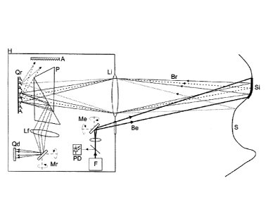
Figure 1 illustrates part of the system proposed by the first aspect of the
invention for
one embodiment for which it comprises, arranged in a casing H:
- illumination means including a light source F, generally laser, and a series
of optical
elements arranged at the outlet of the light source F (beam splitter and
lenses), as well as a
CA 02901100 2015-08-12
17
photodetector PD for detecting the pulse emitted by the light source F and
generating a
corresponding detection signal to be used as the start of time counting for a
pulsed TOF
system. The illumination means are configured and arranged for projecting on
the surface to
be scanned S a light beam Be with a determined divergence for illuminating a
sub-area Si of
the area forming the surface to be scanned S;
- light direction means associated with the illumination means configured for
directing
the light beam Be so that it illuminates different sub-areas Si of the surface
to be scanned S
in an alternating manner, and comprising a reflective and/or deflective device
Me which is
arranged between the light beam Be and the surface to be scanned S and which
is movable
rotating, for the illustrated embodiment, with respect to two axes (X and Y)
for carrying out
said alternating direction of the light beam Be; for another non-illustrated
embodiment, the
device Me is movable only with respect to one axis, for the purpose of
obtaining only linear
images;
- reception and detection means configured and arranged for receiving and
detecting,
in an alternating manner, corresponding portions of light Br of said light
beam Be reflected on
each of the different sub-areas Si of the surface to be scanned S, where said
reception and
detection means comprise, for the illustrated embodiment:
- an array or grid Qd of light detectors D; and
- light redirection means including:
- an array or grid Qr of light redirection elements GM (such as a DMD, where
the GMs
are groups of mirrors that are digitally controlled in the DMD), in a number
greater than the
number of light detectors D, for receiving the portions of reflected light Br
(in this case
through an optical system Li and a TIR-type (acronym of "Total Internal
Reflection") prism P),
each of them in a respective sub-grid SQr of the grid Qr (see Figures 2, 3 and
4), and
- a reflective element Mr arranged between the grid Qr of the light
redirection
elements GM and the grid of light detectors Qd, which is movable rotating with
respect to two
axes for carrying out the sequential redirection of each of the portions of
reflected light Br
received in each of the sub-grids SQr towards the light detectors D of the
grid Qd (in this
case after being reflected on the prism P and going through an optical system
Lt).
- an element A capable of absorbing and rejecting light not directed by the
grid of the
redirection elements Qr towards the grid of light detectors Qd as established
by a sequential
scanning process.
CA 02901100 2015-08-12
18
Some of the elements of the system, such as the control means, different types
of
electric and electronic circuits, etc., have not been illustrated in Figure 1
so that it is clearer
and facilitates understanding the functions of illumination by sub-areas Si
and the
corresponding reception and detection carried out by same. For example, the
TDC (acronym
of "Time to Digital Converter") circuits used for the measuring TOF between
the signal of the
detector PD and D which will finally determine the distance measurement have
not been
depicted.
Figure 1 illustrates, by means of two respective solid lines bearing an arrow,
two
portions Br of light reflected on the sub-area Si which are directed towards
two
corresponding light redirection elements GM of the grid Qr redirecting them
towards the grid
Qd of light detectors D, as well as, in dashed line, a portion of light
reflected on the area of
the surface Si, originating from the light beam Be, which will go to a light
redirection element
GM redirecting it towards a light absorber element A, so that it does not
interfere with the
signals of interest. A sequential process controls which GMs direct light
towards the
detectors and which ones direct light towards the absorber A. A portion of
light reflected on
another area of the surface S and not originating from the light beam Be,
which will go to a
light redirection element GM redirecting it towards the light absorber element
A, also so that
it does not interfere with the signals of interest, is also depicted in dotted
line.
For a preferred embodiment, SiPM (acronym of "Silicon Photomultiplier'')
detectors
are used as light detectors D due to their high gain (>106), high bandwidth
and their capability
for detecting the portions of reflected light Br in the form of pulses, by
means of a photon
count configuration or edge triggered configuration, which allows detecting
extremely weak
light pulses of the order of dozens of photons/pulse, far away from the
capability of APD
(acronym of "Avalanche Photodiodes") detectors or PIN photodiodes of standard
TOE units.
Due to the fact that silicon-based detectors, such as SiPM detectors, can only
detect
visible light, for another embodiment the system comprises a type of detectors
equivalent to
SiPM detectors in technologies that are not based on silicon (for example,
InGaAs/InP) which
allow light detection in the infrared band, preferably at 1550 nm, for reasons
of eye safety.
Similarly, these detectors in the infrared band would have a sensitivity and
gain of the same
order as SiPM detectors, also allowing detection of amounts of light of the
order of a few tens
of photons.
The SiPM detectors are solid state detectors offering a gain and bandwidth
comparable to that of PMT detectors. They are formed by an array of Geiger-
mode polarized
CA 02901100 2015-08-12
19
avalanche photodiodes on one and the same substrate and under one and the same
polarization voltage. Each of the GM-APDs (acronym of "Geiger-Mode Avalanche
Photodiode) is activated through the absorption of a small amount of photons
obtaining at the
output a current proportional to the number of activated GM-APDs, and
accordingly, to the
amount of received photons. Taking into account that the anodes of each of the
GM-APDs
forming the detector are attached, the total load at the outlet thereof will
be proportional to
the number of activated GM-APDs and will therefore be proportional to the
amount of
detected photons.
For other embodiments, another type of detectors such as photomultiplier
tubes, APD
(acronym of "Avalanche Photodiode"), PIN photodiodes, SPADs (acronym of
"Single Photon
Avalanche Diode"), etc., are used as light detectors, the type of light
detector being selected
according to the application.
Figures 2, 3 and 4 illustrate the scanning of three respective sub-areas Si of
the
surface S by means of the system and method proposed by the present invention
for one
embodiment which has been carried out by means of a sequential scanning of the
surface S
with the light beam Be, starting from the top left sub-area (Figure 2)
following a zigzag
trajectory indicated by the lines bearing an arrow which go through all the
sub-areas Si, one
of the intermediate sub-areas of said trajectory being depicted in Figure 3,
and ending in the
bottom right sub-area of the surface S (Figure 4). The grid of light
redirection elements Or is
optically conjugated with the entire surface to be scanned S.
Starting from Figure 2, said figure shows how the three portions of light of
Br, marked
in solid line, reflected on the sub-area Si will go, after going through the
optical system Li, to
three respective light redirection elements GM of three respective regions Z
of the sub-grid
SQr which, in the event that Qr is a DMD, will be the active scanning region
of the DMD. An
example of a portion of light Br (broken line) reflected on the sub-area Si
which will go to its
respective element GM through the optical system Li and the latter redirects
it to the light
absorber element A for elimination can also be seen. Only one element GM of
each region Z
can redirect light of the beam Br towards a detector D (going through P, Lf
and Mr) because
there is only one detector D for each region Z.
Each of said three light redirection elements GM redirects the received
portions of
reflected light Br towards the reflective element Mr, after the passage
thereof through the
prism P and the optical system Lf, which adopts a position in which the grid
of light detectors
Qd is optically conjugated with the sub-grid SQr, and therefore with the sub-
area Si, such
oi
CA 02901100 2015-08-12
that the three portions of reflected light Br are received, maintaining the
spatial relation, in
three corresponding light detectors D.
The scanning of the rest of sub-areas Si, those of Figures 3 and 4 and the
remaining
ones, is carried out in the same manner as explained in reference to Figure 2,
by means of
5
moving the light beam Be for illuminating each sub-area Si, and
correspondingly moving the
reflective element Mr in a synchronized manner for optically conjugating the
grid of light
detectors Qd with the corresponding sub-grid of light redirection elements
SQr, and for
thereby receiving the portions of reflected light Br received by the
respective sub-grid SQr by
means of the suitable sequential scanning process.
10
According to one embodiment, devices having MEM mirrors, which are mirrors 2
or 3
mm in diameter with the capability of rotating about two axes perpendicular to
one another,
are used as device Me and reflective element Mr, which allows working at high
frequencies
(up to dozens of KHz) without suffering drawbacks like another type of
conventional reflective
elements (vibrations, large sizes or mechanical wear), which allows obtaining
without any
15
problem scanning speeds corresponding with the rate of images per second of
the order of
images/s with images of more than 10K points per image.
The element Mr allows maintaining the spatial continuity between Qr and Qd
which
allows taking advantage of the total number of detectors for each region SQr.
Although Figures 2, 3 and 4 depict each region Z as being formed by one and
the
20 same
number of light redirection elements GM, particularly four, according to the
embodiment, each of these regions can include a different number of elements
GM and/or
each element GM can be formed by a different number of micromirrors (not
illustrated). The
number of GMs will vary according to the size and number of micromirrors that
each one
brings together, according to the configured size thereof (for improving
energy reception, in
25
return sacrificing spatial resolution, or vice versa). It must be taken into
account that the size
of each GM will be variable within the Z limits, i.e., that, at most, a GM
will have a size equal
to that of the entire surface of a region Z, causing only a single GM to fit
therein.
In turn, said drawings depict an array of detectors Qd formed by 3x3
detectors. This
size has been chosen by way of example for this embodiment. Nevertheless, each
sub-grid
30 SQr
must contain divisions Z according to the number and form distribution of the
grid of
detectors Qd. In this case, a grid of detectors Qd with 3x3 detectors has
generated a sub-
division of the sub-grid SQr with 3x3 sub-regions Z.
CA 02901100 2015-08-12
21
In the embodiment illustrated in Figure 2, two of the areas Z, particularly
the central
area and the area occupying the bottom right vertex of SQr, have received a
portion of
reflected light Br only in a single GM of each of them, both having been
redirected completely
once towards corresponding light detectors D of the grid Qd, one towards the
central
.. detector and the other towards the detector occupying the bottom right
vertex of Qd.
In contrast, the area Z located in the top left vertex of SQr has received two
sub-
portions of reflected light Br in two respective GMs, one of which, marked
with solid line, has
been redirected towards a corresponding light detector D of the grid Qd,
particularly the
detector located in the top left vertex thereof, whereas the other, marked
with broken line,
has been diverted towards the absorber element A. In a subsequent moment (not
illustrated),
according to a sequential process, by means of actuation on the GMs, the sub-
portion of
reflected light Br, marked with broken line, is redirected towards the light
detector D of the
top left vertex of Qd, and the one marked with solid line is diverted towards
the absorber
element A, thereby increasing the spatial resolution, since one and the same
light detector D
(or pixel of the array of detectors Qd) receives the portion of light Br
received in several GMs,
in this case in the two GMs of the region Z of the top left vertex of Qr, in
the form of a
sequence of sub-portions.
Such increase in spatial resolution is representative of a preferred
embodiment, and
advantageously also applies to the rest of regions Z receiving reflected light
Br, such that one
and the same detector D receives the portion of light Br received in several
GMs of each
region Z, in the form of a sequence of sub-portions. The GMs which are not
redirecting
portions of light Br during the sequential process are diverted towards the
absorber element
A so that they do not interfere with the signals of interest.
This sequential redirection of sub-portions of the portion of reflected light
is described
in the international patent application W02012123809A1, although applied
simultaneously to
the entire grid Qr, unlike the present invention in which work is carried out
sub-grid by sub-
grid SQr.
Obviously, for a less preferred embodiment, it is possible to use the system
of the
invention without performing such process of sequentially redirecting the sub-
portions of
.. reflected light Br.
By means of this preferred embodiment, a process referred to by the present
inventors as SSDS (acronym of "Semi-Sequential Digital Scanning") process is
obtained.
Considering a light source having specific power and shared between the SSDS
and a
t
CA 02901100 2015-08-12
22
system based on array of detectors completely illuminating the surface being
measured, and
a field of view also shared between both systems, the SSDS system improves the
maximum
measurable distance as a result of its greater energy concentration per unit
of surface. High
performances in scanning speed, spatial resolution or other scanning
properties are
maintained. This improvement in measurement distance is due to the fact that
the
illumination beam does not have to cover the entire area to be scanned but
rather allows
scanning by sub-regions, the illumination energy being able to be concentrated
on a smaller
region in which the points to be measured are located. Use of the element Mr
allows using
the entire array of detectors Qd for each region SQr which prevents underusing
detectors
due to optical discontinuities between the points of the surface and the
detection elements D.
Figure 5 illustrates the basic embodiment described in a preceding section, in
which
the system includes only one light detector D, the size of the region Z would
occupy the
entire sub-grid SQr. Therefore, only one element GM can redirect sub-portions
of light of the
beam Br towards the detector D simultaneously. Particularly, according to said
Figure 5, the
sub-portion marked with solid line is directed towards the only light detector
D, whereas the
two sub-portions marked with broken lines are diverted towards the absorber
element A.
If said SSDS process is implemented for this basic embodiment of Figure 5,
each of
the three sub-portions of reflected light Br will be sequentially redirected
towards the only
light detector D, whereas the other two will be diverted towards the absorber
element A.
It can be said that the system proposed by the present invention allows
obtaining
intermediate results between sequential scanning systems and systems based on
a standard
array of detectors completely illuminating the surface, achieving a balanced
combination of
the properties making it ideal for a wide range of applications. The following
table shows
tentative values obtained by means of a prototype of the SSDS system for TOF
measurements, comparing same with standard and completely tentative values of
the
mentioned systems. It must be pointed out that the values shown in the table,
for the cases
of sequential scanning and array of detectors, are highly variable depending
on the
properties of the light source, field of view, detector sensitivity, etc.
Nevertheless, typical
values that are close to a large amount of commercial systems based on these
technologies
are provided by way of example.
Sequential Based on array
TOF SSDS
scanning of detectors
Measurable distance >10 km <15 m standard >100 m
CA 02901100 2015-08-12
23
Depending on >15 according
laser power to laser power
and FOV
Sensitivity to background light Low High Medium
Scanning speed ("frame rate") ¨1 image/s >60 images/s ¨30 images/s
Variable up to 2
Spatial resolution 100 Kpx 20 Kpx
Mpx
Scanning properties that can
be modified according to No No Yes
external conditions
Size Large Small Small
The amount of light detectors in an array Qd limits the image capturing speed.
The
larger the number of detectors, the higher the measurement speed since more
simultaneous
measurements can be carried out. In the system proposed by the first aspect of
the
invention, given that the spatial resolution is given by the array Qr of light
redirection
elements GM, it is possible to use arrays of light detectors Qd having a small
size (e.g., 4x4
detectors). These arrays having a small size can incorporate more complex TOF
measurement circuits than arrays having a large size (e.g., 128x128 detectors)
used in the
systems based on arrays of detectors since the integration thereof at the
microelectronic
level is much simpler. To that end, the time counting circuits (TDC circuit)
can incorporate
additional functions, such as those relating to measurements in complex
environments,
implemented in the form of circuits optimized for rain, fog, snow, dust and
under foliage
object detection, for example. Furthermore, the divergence of the emitted beam
Be can be
adjusted according to the required performance, and can even be adjusted using
a type of
motorized "zoom".
By means of the method and system proposed by the present invention, in
addition to
being able to modify the spatial resolution for measuring distances,
intelligent object
detection and tracking algorithms based on DMD and SSDS are included for
controlling the
scanning sequence such that they implement object detection and tracking
functions. This
means that the scanning sequence may not be repetitive but rather could focus
only on the
objects identified as "target" and could do without the rest of field of view.
For some
embodiments, movement prediction algorithms are implemented for performing
intelligent
CA 02901100 2015-08-12
24
detection and tracking, these algorithms being able to be run conditioned by
the data
captured by a 2D camera external to the apparatus, i.e., to casing H.
The advantage offered by the use of the DMD by the system and method proposed
by the present invention, with respect to other systems, is that the latter is
digitally controlled
without mechanical movements, which favors running the complex object tracking
and
detection algorithms without mechanical movement limitations of the scanning
system.
Another advantage offered by the system and method proposed by the present
invention, in contrast with conventional systems, is that, for some
embodiments, it allows
varying the scanning parameters in real time, depending on external factors
(or on any
external or internal signal originating from detectors or from local or remote
communication
systems). This quality was referred to by the present inventors as "Dynamic
Scanning", it is a
natural consequence of the digital implementation of the scanning system of
the first aspect
of the invention and allows dealing with a wide range of functionalities
having an added
value, in addition to conventional distance measurements for 3D image, such as
the
following measurements relating to the field of automotive industry:
- Adaptable distance measurement capabilities. As mentioned above, the smaller
the
spatial resolution of the image to be measured, the greater the distance which
can be
measured and also the greater the speed in images per second. This means that
spatial
resolution can be reduced when the external conditions require a long-range
measurement.
For example, in foggy conditions, it is preferable to increase the energy
received by means of
scanning with models including a smaller number of pixels (i.e., configuring
larger GMs by
bringing together a larger number of micromirrors), so the energy lost due to
the effect of the
fog can be compensated for by improvement in energy reception at the expense
of spatial
resolution loss.
- Spatial resolution adaptable to the objects of interest. This is a step
opposite that of
the preceding point. Spatial resolution can be increased by bringing together
a smaller
amount of micromirrors in each GM, to detect with greater precision the
objects of interest in
order to distinguish, for example, pedestrians, artifacts or other objects in
a more precise
manner. By increasing spatial resolution, given one and the same illumination
power, the
measurable distance will be smaller because the energy redirected by each GM
will also be
less. Nevertheless, by increasing the spatial resolution of the image, more
information of
each object can be obtained or smaller objects can be detected. The increase
in resolution
CA 02901100 2015-08-12
can be concentrated on certain areas of the field of view identified as
regions of interest. This
process can be configured on the go.
- Scanning depending on external conditions. Taking the application in the
automotive
industry as an example, driving along an expressway is rather different from
driving along a
5 city. In the first case, the objects of interest are at larger distances.
In such case, by means
of modifying the scanning configuration it is possible to detect the
environment in a more
suitable manner. In the second case, it is preferable to work with a high
spatial resolution and
a shorter distance. Furthermore, it may be useful to configure different
spatial resolutions in
some regions of the image. For example, the side regions can be configured
with a high
10 spatial resolution because pedestrians generally come from the
sidewalks. On the other
hand, upper areas with less interest can be rapidly scanned configuring them
with a lower
spatial resolution.
- Combination of 2D information and data relating to distance. Sometimes 2D
colored
or black and white data can be useful for detecting risk situations, but it is
not very reliable
15 since the lack of depth information causes ambiguities in the analysis
algorithms. A more
precise tool can be obtained by means of combining 2D and 3D data to improve
security and
driving assistance. Digital scanning can complement 2D analysis, providing
information
relating to distance focusing only on the regions of interest.
- The far infrared image (FIR: "Far Infrared Scanning") is useful for
detecting
20 pedestrians in low light conditions. However, without information
relating to distance, image
analysis can lead to false alarms and incorrect interpretations of the scene.
A distance
measurement can contribute in making conventional detection systems more
reliable.
These are only some possible applications of the system and method proposed by
the invention, but there is a wide range of applications which can benefit
from the present
25 invention, particularly when it incorporates the so-called dynamic
scanning. Some of such
applications have already been indicated in a preceding section (intelligent
video
surveillance, supervised semi-automatic or self-guided vehicles, etc.)
Finally, Figure 6 illustrates a flowchart depicting an implementation of the
method
proposed by the second aspect of the invention, for one embodiment for which
the latter
includes the following steps:
El: Start.
E2: Positioning the device or mirror Me in a first position.
E3: Positioning the reflective element Mr in a first position
CA 02901100 2015-08-12
26
E4: Generating a first scanning model of the DMD.
E5: Emitting laser pulse.
E6: Starting time counting with the TDC.
E7: Detecting the pulse of reflected light Br in each detector D of the array
Qd.
E8: Stopping time counting with the TDC.
E9: Obtaining distance value.
El 0: Has scanning of the sub-area Si end?
El 1: Going to the next scanning model of the DMD.
E12: Has TOE scanning of the entire sub-area Si been obtained?
E13: Transmitting data.
E14: Positioning the reflective element Mr for optically conjugating same with
the next
sub-grid SQr of the DMD.
E15: Positioning the device or mirror Me for directing the light beam Be
towards the
next sub-area Si.
As regards the scanning models of the DMD (or of another device used as Qr
instead
of a DMD), these generally refer to the selection of GMs directing light
towards Qd, and the
reason for changing said model in step Eli is generally to redirect another
sub-portion of a
portion Br, or sub-portions of portions Br, towards Qd in order to implement
the embodiment
explained above in which each portion Br would be sequentially redirected in
sub-portions
towards one and the same light detector, although the change of model can also
have other
reasons, such as that relating to the change of the size of each GM, on the
go, in which case
the change of model refers to the selection of micromirrors forming each GM.
Figures 7 to 10 illustrate the scanning of three respective sub-areas Si of
the surface
S by means of the system and method proposed by the present invention for
another
embodiment which has been carried out by means of a sequential scanning of the
surface S
with the light beam Be, starting from the top left sub-area (Figure 7)
following the trajectory
indicated by the lines bearing an arrow going through all the sub-areas Si,
different
intermediate sub-areas of said trajectory being depicted in Figures 8 and 9,
and ending in the
bottom left sub-area of the surface S (Figure 10). The grid of light
redirection elements Qr is
optically conjugated with the entire surface to be scanned S.
Among other features, this embodiment differs from that of Figures 2 to 4 in
that each
sub-model SQr adopts the form of a linear array, formed by an area Z, each of
them formed,
in this case, by eight elements GM, all the elements GM of the linear array
SQr being
fi
CA 02901100 2015-08-12
27
activated, which has been indicated with the reference GM', which is the sum
of all activated
GMs, i.e., eight. The linear arrays SQr are sequentially activated/deactivated
as can be seen
in Figures 7 to 10 for receiving portions of reflected light Br reflected at
all times.
How the light which is reflected on other parts of the grid Or outside the sub-
grid SQr
and which generally comes from the reflection of ambient light on the
corresponding optically
conjugated areas of the surface S, is redirected towards the absorber element
A for the
purpose of blocking same, can be seen. This aspect is also implemented in the
embodiment
of Figures 2 to 4, although for another alternative (and less preferred)
embodiment, this
aspect can be dispensed with. The main function of this functionality is to
block light coming
from the field of view, such that the detector D will only receive light
coming from the points
of the surface S which are optically conjugated with the region SQr=Z=GM'. The
redirection
elements located outside said region SQr=Z=GM' redirect the light to the
element A so that it
is rejected, preventing it from reaching the detector such that it does not
interfere in the
measurement process. According to the ratio between the surface of SQr=Z=GM'
and the
region within Qr redirecting light towards A, a lower or higher percentage of
background light
coming from the areas contained in S which are not being illuminated by the
light source F
will be blocked. The grid Qr is therefore used by way of a light blocking
element by means of
the activation and deactivation of different linear regions.
Different regions Si are sequentially illuminated by means of the light
direction
element Me. These illuminated regions Si generate a reflected beam Br which is
redirected
towards the detector D by means of the linear array region SQr=Z=GM'. As
indicated above,
the surface of the grid Qr which remains outside the region SQr=Z=GM'
redirects the light
towards the element A blocking and absorbing the light.
In this embodiment, the mirror Mr is kept static or inactive, because an
optical system
keeping the detector D (or array of detectors, for another non-illustrated
embodiment)
optically conjugated at all the times with the entire grid Qr, i.e., that is
capable of focusing all
the light coming from the grid Or on the surface of the detector D (or
detectors of an array of
detectors, if this is the case), is used.
Although all the elements GM of the linear array SQr are kept activated, only
the
portion of reflected light Br corresponding to a region Si is received at all
times, and it takes
place in part of the linear array SQr (in this case in a single GM) so the
light detector will
receive such portion Br (together with the residual portion that is reflected
on the rest of
activated GMs, but the latter has an insignificant value).
CA 02901100 2015-08-12
28
Such activation of all the elements GM of the linear array SQr, according to
this
embodiment of Figures 8 to 10, is to allow use thereof with a very quick
scanning system
causing the beam laser Be to move very quickly between the different regions
Si, which
would mean that if the elements GM of the linear array SQr had to be
sequentially activated,
they would have to do same at a speed equal to or greater than that of the
mentioned
scanning, which is not common by means of using the elements available
according to
current technology.
The regions SQr=Z=GM' can have various forms, alternative to those
illustrated, for
example, horizontal, vertical, diagonal with different degree of inclination,
they can even be
formed by more than one region along the grid Qr.
The embodiment illustrated in Figures 2 to 4 could be modified based on the
embodiment of Figures 7 to 10 in order to adapt same to a high scanning speed,
for which
each region SQr illustrated in said drawings would be extended to occupy an
entire line of
sub-grids.
Figure 11 illustrates, by means of a flowchart, an implementation of the
method
proposed by the second aspect of the invention applied to the configuration of
Figures 7 to
10, where the flowchart is applied to the use of a static Mr or an Mr that
does not need to be
moved, because the detector D is permanently optically conjugated with the DMD
as a
whole, i.e., Qr. The flowchart includes the following steps:
Fl: Initialization.
F2: Configuring DMD with the first model SQr=Z=GM'.
F3: Positioning the device or mirror Me in a first position of the
corresponding model
SQr=Z=GM'.
F4: Emitting laser pulse.
F5: Starting time counting with the TDC.
F6: Detecting the pulse of reflected light Br in the detector D.
F7: Stopping time counting of the TDC.
F8: Obtaining distance value.
F9: SQr=Z=GM' ended (i.e., reception of Br in all the GMs of SQr)
Fl 0: Positioning Me for directing the light beam Be towards the next sub-area
Si.
Fl 1: Has TOF scanning of the entire sub-area Si been obtained?
F12: Transmitting data.
11
CA 02901100 2015-08-12
29
F13: Configuring the DMD with the next scanning model of the DMD, i.e.,
deactivating
the present area SQr and activating the next area (in this case the one
immediately
below).
With respect to the chart of Figure 12, said figure illustrates, by means of a
flowchart,
an implementation of the method proposed by the second aspect of the
invention, similar to
that of Figure 11 but applied to a configuration such as that of Figures 7 to
10 but with the
movable reflective element Mr, the flowchart including the movement of Mr for
optically
conjugating the detector D with the suitable QM at all times in a sequential
manner. The
chart includes the following steps:
G1: Initialization.
G2: Configuring DMD with the first model SQr=Z=GM'.
G3: Positioning Me and Mr in a first position of the corresponding model
SQr=Z=GM'.
G4: Emitting laser pulse.
G5: Starting time counting with the TDC.
G6: Detecting the pulse of reflected light Br in the detector D.
G7: Stopping time counting of the TDC.
GB: Obtaining distance value.
G9: SQr=Z=GM' ended (i.e., reception of Br in all the GMs of SQr).
G10: Positioning Me and Mr at the next position, the former (Me) for directing
the light
beam Be towards the next sub-area Si, and the latter (Mr) for optically
conjugating the
detector D with the next GM of SQr.
G11: Has TOE scanning of the entire sub-area Si been obtained?
G12: Transmitting data.
G13: Configuring the DMD with the next scanning model of the DMD, i.e.,
deactivating the present area SQr and activating the next area (in this case,
the one
immediately below).
The flowcharts of Figures 6, 11 and 12 are implemented, for some embodiments,
by
the computer program proposed by the fourth aspect of the invention.
A person skilled in the art would be able to introduce changes and
modifications in
the embodiments described without departing from the scope of the invention as
defined in
the attached claims.