Note: Descriptions are shown in the official language in which they were submitted.
CA 02901177 2015-08-13
WO 2014/143520
PCT/US2014/017480
NEEDLELESS CONNECTOR WITH REDUCED TRAPPED VOLUME
Cross-references to related applications
[0001] Not applicable.
BACKGROUND
Field
[0002] The present disclosure generally relates to needleless connectors, and,
in particular, to
connectors with an internal collapsible valve.
Description of the Related Art
[0003] Medical treatments often include the infusion of a medical fluid, for
example a saline
solution or a liquid medication, to patients using an intravenous (IV)
catheter that is
connected though an arrangement of flexible tubing and fittings, commonly
referred to as an
"IV set," to a source of fluid, for example an IV bag. The fittings commonly
include
interconnectable male and female needleless connectors having a "Luer taper"
conforming to
an International Standards Organization (ISO) standard, although certain
needleless
connectors may not have Luer tapers. Certain connectors have a self-sealing
feature to
prevent leakage of fluid from the attached tubing when the connector is
decoupled from a
mating connector.
[0004] FIG, lA depicts a conventional needleless connector 10 with a
collapsible internal
valve 20 made of a flexible material. When a force is applied to the top 24 of
the valve 20 by
the tip of a male Luer connector (not shown), the valve folds at a "smiley
cut" 26 located in
the upper portion 22, referred to as the "head" of the valve, thereby opening
a flow path
through the connector 10. In the closed position shown in FIG. 1A, a primary
seal is formed
between a shoulder 30 of the valve 20 and a sealing ridge 54 of the body 50
and a secondary
seal is formed between the rim around the external surface 24 of the valve 20
and the edge of
the port 52 of the body 50. Between the primary and secondary seals and
between the
body 50 and the valve 20, a volume 53 is formed that contains trapped liquid
when the
connector 10 is de-mated from a previously connected male Luer connector. In
certain
circumstances, it is desirable to minimize volume 53.
SUMMARY
[0005] The self-sealing female needleless connector disclosed herein has a
reduced intemal
volume compared to conventional connectors of the same type and, therefore,
may trap a
reduced amount of fluid within the connector upon disconnection.
[0006] In certain embodiments, there is described a female connector
comprising: a body
comprising an internal cavity having a port and an internal surface; and a
collapsible valve
disposed within the internal cavity, the valve comprising: a head comprising
an external
surface and a shoulder, wherein the head is in sealing contact with the
internal surface of the
internal cavity at a first location separated from the port so as to create a
primary seal at the
shoulder and at a second location proximate to the port so as to form a
secondary seal when
the female connector is not mated with a compatible male connector; a neck
having a distal
end and a proximal end, the distal end of the neck coupled to the head
proximally of the
primary seal, the neck comprising a concave cut-out at its outer surface of
half the thickness
of the neck; and a base portion having an internal volume, the base portion
coupled to the
proximal end of the neck.
[0007] In certain embodiments, there is described a connector comprising: a
body comprising
an internal cavity having a port; and a collapsible valve disposed within the
internal cavity,
the valve having distal and proximal ends and comprising: a head comprising an
external
surface disposed at a distal end and a ridge that is proximal to and separated
from the external
surface; a neck having a distal end and a proximal end, the distal end of the
neck coupled to
the head proximally of the ridge, the neck comprising an outer surface having
a concave cut-
out, between the distal end and the proximal end, of half the thickness of the
neck; and a base
portion having an internal volume, the base portion coupled to the proximal
end of the neck,
wherein the ridge of the valve is in sealing contact with the body so as to
form a primary seal
when the connector is not mated with a compatible connector.
[0008] In certain embodiments, there is also described a female connector
comprising: a body
having distal and proximal ends and comprising an internal cavity with an
internal surface, a
port at a distal end of the internal cavity, and a ridge formed on the
internal surface, the ridge
being proximal to and separated from the port; and a collapsible valve
disposed within the
2
CA 2901177 2020-03-27
internal cavity, the valve having distal and proximal ends and comprising: a
head comprising
an external surface disposed at a distal end and a shoulder proximal to and
separated from the
external surface; a neck having a distal end and a proximal end, the distal
end of the neck
coupled to the head proximally of the shoulder, the neck comprising an outer
surface having a
concave cut-out, between the distal end and the proximal end, of half the
thickness of the
neck; and a base portion having an internal volume, the base portion coupled
to the proximal
end of the neck, wherein the ridge of the body is in sealing contact with the
shoulder so as to
create a primary seal when the female connector is not mated with a compatible
connector.
BRIEF DESCRIPTION OF THE DRAWINGS
100091 The accompanying drawings, which are included to provide further
understanding and
are incorporated in and constitute a part of this specification, illustrate
disclosed embodiments
and together with the description serve to explain the principles of the
disclosed
embodiments. In the drawings:
100101 FIGS. IA-1B are cross-sections of a conventional needleless connector.
[0011] FIG. 2 is a perspective view of an exemplary internal valve for a
needleless connector
according to certain aspects of the present disclosure.
[0012] FIGS. 3-4 are cross-sections of an exemplary needleless connector that
includes the
valve of FIG. 2 according to certain aspects of the present disclosure.
[0013] FIG. 5 is an enlarged view of a portion of the needleless connector of
FIG. 3
according to certain aspects of the present disclosure.
100141 FIGS. 6A-6B are enlarged views of a portion of another embodiment of a
needleless
connector according to certain aspects of the present disclosure.
3
CA 2901177 2020-03-27
DETAILED DESCRIPTION
[0015] It is advantageous to provide a self-sealing, needleless connector that
accepts male
Luer fittings that meet the ISO standard while the size of the connector, and
therefore the
volume of fluid within the connector, is reduced compared to conventional
connectors.
[0016] In the following detailed description, numerous specific details are
set forth to provide
a full understanding of the present disclosure. It will be apparent, however,
to one ordinarily
skilled in the art that embodiments of the present disclosure may be practiced
without some of
the specific details. In other instances, well-known structures and techniques
have not been
shown in detail so as not to obscure the disclosure. In the referenced
drawings, like numbered
elements are the same or essentially similar. Reference numbers may have
letter
3a
CA 2901177 2020-03-27
CA 02901177 2015-08-13
WO 2014/143520
PCMJS2014/017480
suffixes appended to indicate separate instances of a common element while
being referred to
generically by the same number without a suffix letter.
100171 FIGS. 1A-1B are cross-sections of a conventional needleless connector
10. With
reference to FIG. 1A, the connector 10 includes a collapsible valve 20
disposed within a
internal cavity 51 of body 50. The valve 20 has a shoulder 30 that
continuously contacts a
ridge 54 within the internal cavity 51 when the connector 10 is de-activated,
i.e. not
connected to a mating connector, to form a primary seal that blocks the fluid
flow path
through the connector 10. The valve 20 has an internal air space 32 that is
separated from the
internal cavity 51 by a cylindrical wall 28. The air space 32 is vented to the
ambient
environment through air passages 56 and the external cavity 58 within the
threaded
connector 38 surrounding the male Luer fitting 39 of the body 50, as indicated
by the air flow
path 70. The valve 20 also has a solid head 22 with a "smiley cut" 26 formed
on one side and
a external surface 24 that is positioned generally flush with a port 52 of the
internal cavity 51
when the connector 10 is de-activated. The external surface 24 is continuous,
i.e. there is no
slit or penetration in the surface that may trap bacteria or other
contamination. The edge of
the external surface 24 seals to the port 52 to form a secondary seal.
[0018] FIG. 1B depicts an enlarged portion of FIG. 1 defined by the dashed-
line box labeled
"B." The portion of internal cavity 51 that is between the primary and
secondary seals, and
external to the valve 20, is a trapped volume 53 that encircles the head 22
and fills the sm i ley
cut 26.
[0019] FIG. 2 is a perspective view of an exemplary internal valve 100 for a
needleless
connector according to certain aspects of the present disclosure. The valve
100 has a
head 110, a neck 120, and a base portion 130 arranged along a distal-proximal
axis 101. As
shown in FIG. 2, the head 110 comprises an external surface 112 and a shoulder
116 that is
proximal to the external surface 112. The neck 120 is coupled to the head 110
proximal to
the shoulder 116 and comprises a smiley cut 122. The base portion 130 is
coupled to the
neck 120 proximal to the smiley cut 122. In certain embodiments, the valve 100
is formed as
a single piece while, in other embodiments, the valve 100 may be formed by
coupling two or
more elements, for example by adhesive bonding. In certain embodiments, the
valve 100
comprises an elastomeric material, for example a silicone. In certain
embodiments, the
valve 100 may comprise rigid or semi-rigid materials, for example a
polyethylene.
4
CA 02901177 2015-08-13
WO 2014/143520
PCMJS2014/017480
[0020] In this example, the base portion 130 has an external dimple 132 and an
internal
volume 134, visible in the cutaway portion of the base portion 130, that is
open at the
proximal end of the base portion 130. The dimple 132 controls the collapse of
the base
portion 130 under a compressive load when the connector 10 is actuated as
shown in FIG. 4.
[0021] The neck 120 has a smiley cut 122 that is, in this example,
approximately half the
thickness of the neck 120. The smiley cut 122 controls how the neck 120 folds
under the
same compressive load, as shown in FIG. 4. The smiley cut 122 has a depth 124
measured as
the maximum distance from the curved surface of the smiley cut 122 to a
reference feature
defined by a continuation of the cylindrical surface of the neck 120 over the
smiley cut 122.
In certain embodiments, the smiley cut 122 has a constant profile across the
cut while, in
other embodiments, the smiley cut 122 may have curvature perpendicular to the
distal-
proximal axis 101. In certain embodiments,-the smiley cut 122 is symmetric
while, in other
embodiments, the smiley cut 122 may have a non-symmetric profile. In certain
embodiments, the smiley cut 122 has the form of a continuous curve while, in
other
embodiments, the smiley cut 122 may have corners and/or flat surfaces.
[0022] The head 110 comprises a cylindrical portion 114 and an extended
portion 118, with
the shoulder 116 disposed between the portions 114 and 118. In certain
embodiments, the
head 110 is solid while, in other embodiments, the head 110 may have an
internal recess (not
visible in FIG. 2).
[0023] The shoulder 116, in this example, extends outward at an angle from the
cylindrical
portion 114 in a proximal direction. In certain embodiments, the angle of the
shoulder 116 is
in the range of 15-75 . In certain embodiments, the angle is in the range of
30-60 . In
certain embodiments, the angle is approximately 40 .
[0024] In certain embodiments, there is a raised ridge 113 formed around the
head 110 at the
edge of the external surface 112. In certain embodiments, there is a raised
ridge 117 formed
around the head 110 at the interface between the shoulder 116 and extension
portion 118.
The ridges 113 and 117 are discussed in greater detail with respect to FIG. 5.
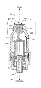
[0025] FIGS. 3-4 are cross-sections of an exemplary needleless connector 300
that includes
the valve 100 of FIG. 2 according to certain aspects of the present
disclosure. The
connector 300 is defined as a "female" valve that is configured to separably
mate with a
compatible "male" connector (not shown in FIG. 3). FIG. 3 depicts the
connector 300 in a
CA 02901177 2015-08-13
WO 2014/143520
PCMJS2014/017480
first configuration wherein the connector 300 is not mated with a compatible
male connector.
The connector 300 has a distal-proximal axis 301 and, in certain embodiments,
the
connector 300 is generally symmetric about the axis 301.
[0026] The connector 300 comprises a body 200 with an internal cavity 210
having a
port 215 disposed, in this example, at a distal end of the body 200. The
internal cavity 210
has an internal surface 220. The body 200 includes an output flow channel 206
that is, in this
example disposed at the proximal end. A passage 204 connects the internal
cavity 210 to the
output flow channel 206 in a plane that is perpendicular to the plane of the
cross-section in
FIG. 3.
[0027] The valve 100 is disposed within the internal cavity 210 with the
external surface 112
approximately flush with the surface 217 that surrounds the port 215. The head
110 is
disposed within a cylindrical portion 211 of the internal cavity 210 that is
proximate to the
port 215 so as to form a trapped volume 310. The details of this region of
connector 300 are
discussed in greater detail with respect to FIG. 5.
[0028] FIG. 4 depicts the connector 300 in a second configuration wherein the
connector 300
is mated with a compatible male connector having a male fitting 2 with an
internal flow
passage 4. The fitting 2 has been inserted through port 215 into cylindrical
portion 211 of the
internal cavity 210, thereby displacing the head 110 of valve 100 and applying
a compressive
load to the head 110 in a proximal direction along the distal-proximal axis
301. The
compressive load is transferred through the neck 120 and base portion 130 to
the body 200,
causing the neck 120 to fold and the base portion 130 to collapse generally as
depicted in
FIG. 4. The deformed configuration of valve 100 is only illustrative and other
deformed
positions of the valve 100 are within the scope of this disclosure. Once the
fitting 2 is fully
mated with the connector 300, a fluid flow path 302 is opened from the
internal flow
passage 4 through the internal cavity 210 around the collapsed valve 100 and
through
passage 204 to the output flow channel 206.
[0029] FIG. 5 is an enlarged view of a portion of the needleless connector 300
of FIG. 3
according to certain aspects of the present disclosure. In this enlarged view,
the ridge 113
formed around the edge of the external surface 112 and the ridge 117 formed at
the juncture
of the shoulder 116 and extended portion 118 are visible. When the connector
300 is in the
first configuration of FIG. 3, the ridge 117 is in sealing contact with the
surface 220 of the
internal cavity 210, thereby forming a primary seal that blocks the fluid flow
path 302. At
6
CA 02901177 2015-08-13
WO 2014/143520
PCMJS2014/017480
the same time, while connector 300 is in the first configuration, the ridge
113 is in sealing
contact with the body 200, thereby forming a secondary seal that also blocks
the fluid flow
path 302 as well as preventing any liquid within the internal cavity 210 from
leaking from the
port 215 after a male connector is removed. A trapped volume 310 is formed
within the
internal cavity 210 and defined as the volume bounded by the primary and
secondary seals,
the head 110, and the body 200.
[0030] In certain embodiments, the head 110 has a diameter D1, excluding the
ridge 113. In
certain embodiments, DI is less than or equal to 0.20 inch. In certain
embodiments, D1 is
approximately equal to 0.17 inch. In certain embodiments, the cylindrical
portion 211 has a
diameter D2 that is greater than DI by a difference that is less than or equal
to 0.010 inch. In
certain embodiments, the ridges 113 and 117 are separated along the distal-
proximal axis 301
by a distance 316 that is less than or equal to 0.10 inch. In certain
embodiments, the trapped
volume 310 is less than or equal to 0.00004 cubic inch.
[0031] FIGS. 6A-6B are enlarged views of a portion of another embodiment 600
of a
needle less connector according to certain aspects of the present disclosure.
FIG. 6A depicts a
body 500 that forms part of connector 600. The body 500 has an internal cavity
510 with a
cylindrical portion 512 disposed proximate to a port 515 having a surrounding
surface 530.
A ridge 525 is formed on the surface 220 of the cavity 510. In certain
embodiments, the
ridge 525 lies in a plane 514 that is perpendicular to a distal-proximal axis
501. The
body 500 comprises a ridge 530 formed around the port 515 and protruding into
the
cylindrical portion 512.
[0032] FIG. 6B depicts a valve 400 disposed within the body 500 of FIG. 5 to
form a
connector 600. The valve 400 is generally similar to valve 100, having a head
410 with an
external surface 412, a cylindrical portion 414, and a shoulder 416, except
that valve 400
lacks the ridges 113 and 117 of valve 100. When connector 600 is in a
configuration wherein
the connector 300 is not mated with a compatible male connector, the external
surface 412 of
valve 400 is approximately flush with the port 515 and the shoulder 416 is in
sealing contact
with the ridge 525 to form a primary seal and ridge 530 is in sealing contact
with the
head 414 to form a secondary seal. The space within the internal cavity 510
between the
primary and secondary seals, the head 410, and body 500 forms the trapped
volume 610.
[0033] In certain embodiments, the head 410 has a diameter D3. In certain
embodiments, D3
is less than or equal to 0.20 inch. In certain embodiments, D3 is
approximately equal to
7
CA 02901177 2015-08-13
WO 2014/143520
PCT/1JS2014/017480
0.17 inch. In certain embodiments, the cylindrical portion 512 has a diameter
D4 that is
greater than D3 by a difference that is less than or equal to 0.050 inch. In
certain
embodiments, the ridges 525 and 530 are separated along the distal-proximal
axis 301 by a
distance 516 that is less than or equal to 0.20 inch. In certain embodiments,
the trapped
volume 610 is less than or equal to 0.01 cubic inch.
[0034] In summary, the positioning of the primary seal distal to the smiley
cut of valve
provides a reduced volume of fluid trapped between the primary and secondary
seals. This
may reduce the amount of liquid that may leak past the secondary seal or
improve the sealing
performance due to the improved alignment of the primary and secondary seals.
[0035] The previous description is provided to enable any person skilled in
the art to practice
the various aspects described herein. While the foregoing has described what
are considered
to be the best mode and/or other examples, it is understood that various
modifications to these
aspects will be readily apparent to those skilled in the art, and the generic
principles defined
herein may be applied to other aspects. Thus, the claims are not intended to
be limited to the
aspects shown herein, but are to be accorded the full scope consistent with
the claim
language.
[0036] Reference in the claims or specification to an element in the singular
is not intended
to mean "one and only one" unless specifically so stated, but rather "one or
more." Unless
specifically stated otherwise, the terms "a set" and "some" refer to one or
more. Pronouns in
the masculine (e.g., his) include the feminine and neuter gender (e.g., her
and its) and vice
versa.
[0037] Headings and subheadings, if any, are used for convenience only and do
not limit the
disclosure.
[0038] It is understood that the specific order or hierarchy of steps of
methods disclosed in
the specification is an illustration of exemplary approaches. Based upon
design preferences,
it is understood that the specific order or hierarchy of steps in the
processes may be
rearranged. Some of the steps may be performed simultaneously. Method claims
present
elements of the various steps in a sample order, and are not meant to be
limited to the specific
order or hierarchy presented.
8
[0039] Terms such as "top," "bottom," "front," "rear," and the like as used in
this disclosure
should be understood as relative references within an arbitrary frame of
reference, rather than
to the ordinary gravitational frame of reference. Thus, a top surface may
extend upwardly,
downwardly, diagonally, or horizontally in a gravitational frame of reference.
[0040] A phrase such as an "aspect" does not imply that such aspect is
essential to the subject
technology or that such aspect applies to all configurations of the subject
technology. A
disclosure relating to an aspect may apply to all configurations, or one or
more configurations.
A phrase such as "an aspect" may refer to one or more aspects. A term such as
"embodiment"
does not imply that such embodiment is essential to the subject technology or
that such
embodiment applies to all configurations of the subject technology. A
disclosure relating to
"an embodiment" may refer to one or more embodiments or to all embodiments.
[0041] The word "exemplary" is used herein to mean "serving as an example or
illustration."
Any aspect or design described herein as "exemplary" is not necessarily to be
construed as
preferred or advantageous over other aspects or designs.
[0042] The terms "include," "have," "with," and the like that are used in the
claims or
specification are intended to be inclusive in a manner similar to the manner
in which
"comprise" is interpreted when employed as a transitional word in a claim.
[0043]
[0044] All structural and functional equivalents to the elements of the
various aspects
described throughout this disclosure that are known or later come to be known
to those of
ordinary skill in the art are expressly incorporated herein by reference and
are intended to be
encompassed by the claims. Moreover, nothing disclosed herein is intended to
be dedicated to
the public regardless of whether such disclosure is explicitly recited in the
claims.
9
CA 2901177 2020-03-27