Note: Descriptions are shown in the official language in which they were submitted.
CA 02901318 2015-08-13
WO 2014/134142
PCT/US2014/018625
ENERGY STORAGE DEVICE ASSEMBLY
[0001] This application claims priority to previous US Provisional Patent
Applications
Number 61/769,937 filed February 27, 2013, and 61/837,311 filed June 20, 2013,
both of
which are hereby incorporated by reference.
BACKGROUND OF THE INVENTION
[0002] This disclosure relates generally to energy storage devices, and
more particularly,
to a modular assembly for one or more energy storage devices, including
capacitors,
ultracapacitors, and batteries.
[0003] In conventional capacitor assemblies, a plurality of capacitor
cells, ultracapacitor
cells, batteries, or other energy storage devices are loosely held together,
through securing
components, within a housing that can subject the cells to a certain amount of
external forces,
including vibratory forces. In some cases, these forces can exceed the
strength of the
securing components. In such cases, vibratory action can dislodge, rotate,
wear and/or
destroy portions of the devices and connections within and/or between them.
This situation
can reduce the durability and lifespan of the energy storage devices.
[0004] Some energy storage devices, including those with capacitor
assemblies, may use
adhesive substances and thermal inserts between capacitor cells. These
components can
dissipate heat generated during operation and reduce rotation and dislodging
of the capacitor
cells within the assembly, but are typically placed between capacitors and may
be located
along or nearby the path of an electric current. To connect energy storage
devices together,
complex bonding mechanisms between numerous surfaces may be used. These design
1
CA 02901318 2015-08-13
WO 2014/134142 PCT/US2014/018625
choices have proven to impair the performance of energy storage devices, and
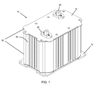
can limit the
opportunity to make further modifications.
[0005] Some capacitor assemblies use bus bars with circular ends to connect
capacitor
cells to one another. These bus bars can be designed to fully surround each
end of a capacitor
cell or an electrode. These circular ends must be precisely machined as close
as possible to
the shape of the end of the capacitor cell for the bus bars to properly
contact and connect with
a device. This limitation can greatly increase manufacturing time and/or
produce an
imprecise fit, leading to faulty and/or inconsistent performance.
[0006] In previous energy storage devices, such as traditional capacitor
cells, a terminal is
attached to an end of the cell through a radial weld or radial interference
fit at an interface
between the cell and the terminal. These points of attachment used complex
geometries, with
weld bonds located at several points of contact. Attachment points according
to previous
designs could cause difficulty or added complexity in manufacturing processes.
In addition,
a radial weld or radial interference fit can also cause attachment points
between the cell and
terminal to perform inefficiently or include imprecise geometrical
connections.
BRIEF DESCRIPTION OF THE INVENTION
[0007] A first aspect of the present disclosure includes an energy storage
device assembly
comprising a plurality of energy storage devices, each energy storage device
having a first
projecting electrode and a second projecting electrode; and a weld directly
bonding adjacent
first and second projecting electrodes of adjacent energy storage devices to
one another in
series.
[0008] A second aspect of the present disclosure includes a bus bar
comprising: a base;
and a pair of opposing, arcuate ends coupled by the base, the pair of
opposing, arcuate ends
2
CA 02901318 2015-08-13
WO 2014/134142 PCT/US2014/018625
configured to engage and only partially surround two substantially circular
projecting
electrodes of two adjacent energy storage devices.
[0009] Another aspect of the invention includes An apparatus for use in an
energy storage
device assembly including a plurality of energy storage devices, the apparatus
comprising: a
structural thermal bridge including at least one thermal plate configured to
engage an end of
at least a pair of the plurality of energy storage devices to physically
secure the energy
storage devices and thermally communicate heat therefrom; and an elongated
sleeve housing
surrounding the plurality of energy storage devices, and the structural
thermal bridge further
comprises: a first thermal plate positioned between the elongated sleeve
housing and a first
end of the at least a pair of the plurality of energy storage devices, the
first thermal plate
including a plurality of recesses shaped to correspond to the first end of the
at least a pair of
the plurality of the energy storage devices; and a second thermal plate
positioned between the
elongated sleeve housing and a second end of at least a pair of the plurality
of energy storage
devices, the second thermal plate including a plurality of recesses shaped to
correspond to the
second end of the at least a pair of the plurality of energy storage devices.
[0010] A further aspect of the invention includes a housing for an energy
storage device
assembly comprising: an elongated sleeve having a contoured interior
configured to enclose
and contact each of a plurality of energy storage devices and a mount
configured to retain a
circuit board to the elongated sleeve housing.
[0011] An additional aspect of the invention includes an energy storage
device assembly
comprising: a plurality of energy storage devices, each energy storage device
including a first
projecting electrode and a second projecting electrode; and a weld bond
electrically
connecting respective first and second projecting electrodes of adjacent
energy storage
devices end-to-end.
3
CA 02901318 2015-08-13
WO 2014/134142 PCT/US2014/018625
[0012] Another aspect of the invention includes An energy storage device
assembly
comprising: a plurality of axially aligned energy storage devices each having
electrodes,
immediately adjacent energy storage devices being connected at a joint; an
elongated sleeve
housing having a length, the elongated sleeve housing enclosing the plurality
of energy
storage devices; a circuit board extending along the length of the elongated
sleeve housing;
and a plurality of substantially identical wiring harnesses for coupling the
circuit board to the
plurality of axially aligned energy storage devices.
[0013] The illustrative aspects of the invention are designed to solve one
or more of the
problems herein described and/or one or more other problems not discussed.
BRIEF DESCRIPTION OF THE DRAWINGS
[0014] These and other features of the disclosure will be more readily
understood from
the following detailed description of the various aspects of the invention
taken in conjunction
with the accompanying drawings that depict various aspects of the invention.
[0015] FIG. 1 shows an isometric view of an energy storage device assembly
according
to embodiments of the invention.
[0016] FIG. 2 shows an exploded view of an energy storage device assembly
according to
embodiments of the invention.
[0017] FIG. 3 shows a perspective view of several energy storage devices
according to
embodiments of the invention.
[0018] FIG. 4 shows a side view of two energy storage devices connected end-
to-end
according to embodiments of the invention.
4
CA 02901318 2015-08-13
WO 2014/134142
PCT/US2014/018625
[0019] FIG. 5 shows a perspective view of a laser welding process according
to
embodiments of the invention.
[0020] FIG. 6 shows a side view of energy storage devices with a thermal
insert
according to embodiments of the invention.
[0021] FIG. 7A shows a perspective view of a thermal insert according to
embodiments
of the invention.
[0022] FIG. 7B shows a perspective view of two sub-portions of a thermal
insert
according to embodiments of the invention.
[0023] FIG. 7C shows a perspective view of a thermal insert located on a
projecting
electrode of an energy storage device, according to an embodiment of the
invention.
[0024] FIG. 7D shows a perspective view of several energy storage devices
in an
assembly, with thermal inserts provided at joints between each energy storage
device.
[0025] FIG. 8A shows a side view of energy storage devices with a thermal
conducting
layer according to embodiments of the invention.
[0026] FIG. 8B shows a cross-sectional view of energy storage devices with
a thermal
conducting filler according to embodiments of the invention.
[0027] FIG. 9 shows a perspective view of an elongated sleeve housing
according to
embodiments of the invention.
[0028] FIG. 10 shows a perspective view of an elongated sleeve housing and
circuit
board according to embodiments of the invention.
CA 02901318 2015-08-13
WO 2014/134142 PCT/US2014/018625
[0029] FIG. 11A shows a schematic view of a circuit board coupled to energy
storage
devices via a set of a single type of wiring harness according to embodiments
of the
invention.
[0030] FIG. 11B shows an alternate, perspective view of a circuit board
coupled to
energy storage devices using a single type of wiring harness with a housing
removed,
according to an embodiment of the invention.
[0031] FIG. 12 shows a perspective view of a structural thermal bridge and
energy
storage devices according to embodiments of the invention.
[0032] FIG. 13 shows a perspective view of a thermal plate, bus bar, and
terminal
according to embodiments of the invention.
[0033] FIG. 14 shows a thermal plate, and an energy storage device with
connected
terminal according to embodiments of the invention.
[0034] FIG. 15 shows a perspective view of a terminal according to
embodiments of the
invention.
[0035] FIG. 16 shows a perspective view of a terminal in position on an
energy storage
device according to embodiments of the invention.
[0036] FIG. 17 shows a perspective view of a terminal bonded to an energy
storage
device according to embodiments of the invention.
[0037] FIG. 18 shows a perspective view of a terminal passing through a
structural
thermal bridge according to embodiments of the invention.
[0038] FIG. 19 shows several bus bars and terminals connected to energy
storage devices
according to embodiments of the invention.
6
CA 02901318 2015-08-13
WO 2014/134142
PCT/US2014/018625
[0039] FIG.
20 shows a perspective view of a bus bar according to embodiments of the
invention.
[0040] It is noted that the drawings of the invention are not necessarily
to scale. The
drawings are intended to depict only typical aspects of the invention, and
therefore should not
be considered as limiting the scope of the invention. It is understood that
elements similarly
numbered between the figures may be substantially similar as described with
reference to one
another. Further, in embodiments shown and described with reference to FIGS. 1-
20, like
numbering may represent like elements. Redundant explanation of these elements
has been
omitted for clarity. Finally, it is understood that the components of FIGS. 1-
20 and their
accompanying descriptions may be applied to any embodiment described herein.
The
detailed description explains embodiments of the invention, together with
advantages and
features, by way of example with reference to the drawings.
DETAILED DESCRIPTION OF THE INVENTION
[0041] In the following description, reference is made to the accompanying
drawings that
form a part thereof, and in which is shown by way of illustration specific
exemplary
embodiments in which the present teachings may be practiced. These embodiments
are
described in sufficient detail to enable those skilled in the art to practice
the present teachings
and it is to be understood that other embodiments may be used and that changes
may be made
without departing from the scope of the present teachings. The following
description is,
therefore, merely illustrative.
[0042] When
an element or layer is referred to as being "on," "engaged to," "disengaged
from," "connected to" or "coupled to" another element or layer, it may be
directly on,
engaged, connected or coupled to the other element or layer, or intervening
elements or layers
7
CA 02901318 2015-08-13
WO 2014/134142 PCT/US2014/018625
may be present. In contrast, when an element is referred to as being "directly
on," "directly
engaged to," "directly connected to" or "directly coupled to" another element
or layer, there
may be no intervening elements or layers present. Other words used to describe
the
relationship between elements should be interpreted in a like fashion (e.g.,
"between" versus
"directly between," "adjacent" versus "directly adjacent," etc.). As used
herein, the term
"and/or" includes any and all combinations of one or more of the associated
listed items.
[0043] Spatially relative terms, such as "inner," "outer," "beneath",
"below", "lower",
"above", "upper," "inlet," "outlet" and the like, may be used herein for ease
of description to
describe one element or feature's relationship to another element(s) or
feature(s) as illustrated
in the figures. Spatially relative terms may be intended to encompass
different orientations of
the device in use or operation in addition to the orientation depicted in the
figures. For
example, if the device in the figures is turned over, elements described as
"below" or
"beneath" other elements or features would then be oriented "above" the other
elements or
features. Thus, the example term "below" can encompass both an orientation of
above and
below. The device may be otherwise oriented (rotated 90 degrees or at other
orientations)
and the spatially relative descriptors used herein interpreted accordingly.
[0044] The present disclosure generally relates to assemblies of energy
storage devices,
including energy storage device assembly 10 depicted in FIGS. 1 and 2.
According to
embodiments of the disclosure, assembly 10 can permit several energy storage
devices to be
electrically connected to each other in series, with a joint such as a weld
bond joining an
electrode on an energy storage device with a successive energy storage device.
As described
in further detail herein, applying a weld bond to connect several energy
storage devices in a
series arrangement can avoid the use of components with higher resistances,
such as
conventional bus bars. Thus, assembly 10 can allow more energy storage devices
to be
8
CA 02901318 2015-08-13
WO 2014/134142 PCT/US2014/018625
joined by series connections, thereby providing a more effective energy
storage apparatus
that avoids the use of conventional bus bars.
[0045] Energy storage device assembly 10 can also be modular and thus
scaled or altered
to interact with a plurality of energy storage devices (e.g., sets of
capacitors, sets of
ultracapacitors, batteries, etc.), according to embodiments of the invention.
For instance,
energy storage device assembly 10 can be selected to contain a number of
energy storage
devices that allows for assembly 10 to have a predetermined operational value,
including a
predetermined voltage or capacitance. In other embodiments, energy storage
device
assembly can have several rows, with each row containing, for example, one,
eight, ten,
twenty, or any desired number of energy storage devices per row, with a number
selected to
yield a desired or pre-defined operational value. Several energy storage
device assemblies 10
can be coupled together in a plurality of conceivable mounting variations,
such as being
stacked together, placed side-by-side, etc. (e.g., FIGS. 2, 6, 7D, 8A, 8B,
11B). In addition,
the lengths of energy storage devices can be altered to provide discrete
operational values for
each device, and thus a different cumulative value for the assembly as a
whole. Despite any
changes in the size of energy storage devices, the same housing can be
employed by cutting
an extrusion of the housing to size, thus reducing manufacturing costs and
complexity and
providing flexibility in customizing for each different assembly's operational
performance.
[0046] In some embodiments, energy storage device assembly 10 can include a
first plate
12 and a second plate 14 located at opposing ends of a housing of energy
storage device
assembly 10. In some embodiments, and as further described herein, embodiments
of the
invention can include housings in the form of an elongated sleeve housing 20.
Elongated
sleeve housing 20 can be configured to contain various devices for
electrically storing energy,
including capacitor cells, ultracapacitors, batteries, and similar components.
First and second
9
CA 02901318 2015-08-13
WO 2014/134142
PCT/US2014/018625
plates 12, 14 can be located at opposing ends of elongated sleeve housing 20.
First and
second plates 12, 14, can include apertures 25 dimensioned to complement
terminals 26 of
devices 100, which can have connectors 28 mounted thereon, allowing them to
pass through
aperture 25. One or more terminals 26 can be made from an electrically
conductive material,
and terminals 26 can extend substantially through first or second plates 12,
14 via one or
more corresponding apertures 25. First plate 12, second plate 14, and
elongated sleeve
housing 20 can also substantially enclose or fluidly isolate the contents of
energy storage
device assembly 10 and can be connected via adhesives, bolts, clasps, and/or
any other means
of connection. Together, as will be described herein, first plate 12 and
second plate 14 can
define a structural thermal bridge 50, which can allow thermal communication
between
elongated sleeve housing 20 and its contents or the environment beyond energy
storage
device assembly 10.
[0047]
Turning to FIG. 2, an exploded view of an embodiment of energy storage device
assembly 10 is shown. Energy storage device assembly 10 can include an
elongated sleeve
housing 20, with optional contours 60, surrounding energy storage devices 100.
Optional
contours 60 can complement and/or allow (thermal and/or actual) contact
between elongated
sleeve housing 20 and at least some or all of energy storage devices 100.
Contours 60 allow
a portion of each energy storage device 100 to contact elongated sleeve
housing 20. In
addition, energy storage devices 100 can be arranged to be in two lateral rows
(along Z axis),
with each row containing any desired number of energy storage devices in an
axial direction
(along X axis). In this fashion, each energy storage device 100 contacts
(thermally and/or
actually) elongated sleeve housing 20 without any energy storage devices 100
being
separated from housing 20 by another energy storage device. In the embodiment
shown,
three lateral columns (along Y axis) are provided, creating a 'six pack'
configuration (Z-Y
CA 02901318 2015-08-13
WO 2014/134142 PCT/US2014/018625
plane). It should be recognized, however, that more or fewer columns may be
provided. In
any event, assembly 10 can be sized to any length capable of providing the
desired
operational performance (e.g., predetermined levels of voltage and/or
capacitance). Energy
storage devices 100 can be any device capable of storing electrical energy,
including
capacitor cells, ultracapacitors, batteries, electrical cells, and other
similar components.
[0048] The embodiment in FIG. 2 is shown to include six axial rows (in X-
axis) of
energy storage devices 100, arranged in a six-pack or side-by-side fashion.
The modular
design of energy storage device assembly 10 and elongated sleeve housing 20
allow
adjustment for accommodating energy storage devices 100 of different sizes and
numbers. In
an example embodiment, energy storage device assembly 10 can include modular a
six-pack
of energy storage devices 100 (e.g., FIGS. 2, 8B). Elongated sleeve housing 20
can be
provided in varying shapes and dimensions to substantially complement, retain,
and/or
matingly receive energy storage devices 100. Retaining contact and/or mating
engagement
between energy storage devices 100 and elongated sleeve housing 20 can
restrict movement
of energy storage devices 100 within elongated sleeve housing 20 and/or
provide thermal
communication between energy storage devices 100 and elongated sleeve housing
20.
[0049] In some embodiments, elongated sleeve housing 20 can substantially
secure a
position of energy storage devices 100 relative to one another and/or
elongated sleeve
housing 20. Elongated sleeve housing 20 can include an electrically and/or
thermally
conductive material, including aluminum and similarly conductive metals. To
provide a
constant cross-sectional area, elongated sleeve housing 20 can be manufactured
by extrusion
and cut to a desired length. Forming elongated sleeve housing 20 by extrusion,
and later
cutting it to the length desired for a design parameter, allows energy storage
device assembly
to be customized and shaped to have different lengths, contain different
numbers of
11
CA 02901318 2015-08-13
WO 2014/134142
PCT/US2014/018625
energy storage devices 100, and/or provide other adjustments without changing
the structure
of elongated sleeve housing 20 and/or energy storage device assembly 10.
[0050]
Energy storage devices 100 can have a generally cylindrical geometry, as shown
in FIG. 2, with a first projecting electrode 102, "projecting" from the end
surface of energy
storage device 100 at one end, and a second projecting electrode 104,
similarly "projecting"
from the end surface of energy storage device 100 at another end. As will be
discussed in
further detail below, first and second projecting electrodes 102, 104 can be
substantially
similar or uniformly sized on each energy storage device 100. Each energy
storage device
100 can include first and second projecting electrodes 102, 104, which can be
configured for
several energy storage devices 100 to be connected to each other in series, as
shown in FIG.
2. Two or more projecting electrodes 102, 104 of energy storage devices 100
can further
include or be circumferentially connected to terminals 26. Terminals 26 can be
either
positive or negative contacts to act as electrical inputs and outputs, through
which external
circuits and devices can electrically access energy storage devices 100.
Assembly 10 can
further include first plate 12, and a first gasket 112 for sealing components
within the
assembly against first plate 12. Similarly, assembly 10 can further include
second plate 14,
and/or a corresponding second gasket 114 for sealing components within the
assembly
against second plate 14. First plate 12, first gasket 112, second plate 14,
second gasket 114,
and elongated sleeve housing 20 can thus be configured to substantially
enclose and/or
fluidly seal energy storage devices 100.
[0051] In
some embodiments, assembly 10 can include a first thermal plate 122 located
proximal to first plate 12 and/or a second thermal plate 124 located near or
proximal to
second plate 14. First and second thermal plates 122, 124 can have any
material composition
capable of communicating thermal energy and/or insulating electricity. For
example, first
12
CA 02901318 2015-08-13
WO 2014/134142 PCT/US2014/018625
and second thermal plates can include a thermal transmitting material, such as
a plastic,
epoxy, phase change material, and/or other similar and equivalent substances
currently
known or later developed. First thermal plate 122 and/or second thermal plate
124 can
include contoured recesses 115 designed to matingly receive or retain energy
storage devices
100 and/or their projecting electrodes 102, 104. Sets of contoured recesses
115 can provide
an interference or plug-style fit with projecting electrodes 102, 104 and/or a
circumferential
fit with energy storage devices 100 themselves, thereby securing a position of
energy storage
devices 100 within elongated sleeve housing 20. In some embodiments, energy
storage
devices 100 can be substantially secured and/or retained between first thermal
plate 122 and
second thermal plate 124 by being connected at first and second projecting
electrodes 102,
104 and/or surrounding structure to first and second thermal plates 122, 124.
[0052] Thermal plates 122, 124 are shown by example in the accompanying
figures as
being in the form of a continuous unit. It is also understood that each
thermal plate 122, 124
can be in the form of several smaller plates, or that thermal plates 122, 124
may each be part
of a larger thermal conduction assembly (e.g., FIGS. 2, 12). Other embodiments
of the
present disclosure can also include thermal insulation along the side of one
or more energy
storage devices 100, as an addition or alternative to thermal insulation at
opposing ends of a
particular row (e.g., FIG. 8). Thermal plates 122, 124 can offer several
commercial and
technical advantages, three examples of which include a high degree of heat
transfer,
improved structural support (including resistance to shocks and vibrations),
and lower
manufacturing costs.
[0053] Assembly 100 can further include one or more bus bars 130 for
electrical coupling
between energy storage devices 100, e.g., by way of projecting electrodes 102
and 104,
directly or through intervening components such as electrodes. Bus bar 130 can
optionally
13
CA 02901318 2015-08-13
WO 2014/134142 PCT/US2014/018625
allow several projecting electrodes 102, 104 of adjacent energy storage
devices 100 to be
connected to each other. In this context, the term "adjacent" can refer to two
or more cells
locations that are immediately next to each other. Hence, bus bar 130 can
connect or couple
two or more energy storage devices 100 through physical connections,
electrical connections,
thermal connections, and other applicable forms of coupling.
[0054] As will be discussed in further detail herein, assembly 100 can
further include a
circuit board 140 coupled to energy storage devices 100. In some embodiments,
a particular
type of wiring harness used uniformly for each energy storage device 100, can
provide
electrical coupling between circuit board 140 and energy storage devices 100.
In addition, an
I/O connector 142 may be located on elongated sleeve housing 20 and coupled to
circuit
board 140 to provide an interface between circuit board 140, energy storage
devices 100, and
a user. Additional details regarding various embodiments of assembly 100 are
discussed
herein.
[0055] An embodiment of the disclosure, illustrated in FIGS. 3-5, provides
an energy
storage device assembly 10 including a plurality of energy storage devices
100, such as
capacitors, capacitor cells, ultracapacitor cells, and other components used
to store energy.
Each energy storage device can further include first projecting electrode 102
and second
projecting electrode 104. First and second projecting electrodes 102, 104, are
depicted as
projecting from the surface of energy storage devices 100 at opposite ends and
having
corresponding substantially circular shapes. However, the disclosure also
contemplates
electrodes designed to have other shapes and geometries. To improve
performance and
reduce the use of components with relatively high resistances, such as
previously discussed
bus bars 130, one or more weld bonds 210 can be provided for direct bonding
between
adjacent first and second projecting electrodes 102, 104 of adjacent energy
storage devices
14
CA 02901318 2015-08-13
WO 2014/134142 PCT/US2014/018625
100. Weld bonds 210 can therefore allow several energy storage devices 100 to
be
electrically connected to each other in series.
[0056] These series connections allow energy storage devices 100 to be
linked in a chain
of weld bonds 210 (also referred to herein as joints), allowing assembly 10 to
be
customizably scaled to applications where more or fewer energy storage devices
100 are
desired. Furthermore, series connections between energy storage devices 100
can allow the
same or similar housings to enclose variable lengths of energy storage devices
100. In some
cases, housings or enclosures for energy storage devices 100 can be
manufactured by
extrusion and then dimensioned (e.g., by cutting) to separate a desired number
of energy
storage devices 100 having a predetermined operational value, such as a
capacitance or
voltage.
[0057] Turning to FIG. 3, a portion of energy storage device assembly 10 is
shown and
can include several energy storage devices 100. In some embodiments, energy
storage
devices 100 can be connected together in series. For example, energy storage
devices 100
can be connected end to end, between first and second projecting electrodes
102, 104.
Individual energy storage devices 100 can be connected to one another
directly, without
intervening elements, between projecting electrodes 102, 104 of energy storage
devices 100
through weld bonds 210. An end-to-end configuration shown in FIGS. 3 and 4 for
connecting energy storage devices 100 in series can further reduce the need
for horizontal
space as compared to situations where energy storage devices are placed in a
side by side
configuration. In some embodiments, energy storage devices 100 may be
connected with
weld bonds 210. Weld bonds 210 can be formed through a spot weld, a
circumferential weld,
a TIG (gas tungsten arc) weld, a MIG (gas metal arc) weld, an EB (electric)
weld, a laser
weld, or any other types of welding currently known or later developed. In one
embodiment,
CA 02901318 2015-08-13
WO 2014/134142 PCT/US2014/018625
laser welding can be used to form weld bond 210 by welding first and second
projecting
electrodes 102, 104 of energy storage devices 100 together along a single
circumferential line
of each immediately adjacent (X-axis FIG. 2) energy storage device 100.
[0058] Joining electrical storage devices 100 in this fashion can reduce
the number of bus
bars 130 used to connect ends of energy storage devices 100, as compared to
assemblies in
which energy storage devices are arranged in a structurally parallel fashion.
Since bus bars
130 can have a relatively high level of electrical resistance, reducing their
use also reduces
resistance in the electrical connections provided between energy storage
devices 100 used in
assembly 10.
[0059] Turning to FIGS. 3-4, an end-to-end configuration of an energy
storage device
assembly 10 can include a plurality of energy storage devices 100, and each of
these units in
the plurality can include first projecting electrode 102 and second projecting
electrode 104 at
opposing ends of each energy storage device 100. As shown previously, energy
storage
devices 100 can be joined directly by a weld bond 210 between first projecting
electrode 102
and second projecting electrode 104. Several weld bonds 210 can be implemented
between
pairs of energy storage devices 100 such that all or a portion of the
plurality of energy storage
devices 100 are electrically connected to each other in series.
[0060] As can be seen in FIG. 4, a first projecting electrode 102 of an
energy storage
device 100 can be connected to a second projecting electrode 104 of an
adjacent energy
storage device 100 via weld bond 210, thereby securely connecting energy
storage devices
100 in series, optionally along a single circumferential line of contact.
First and/or second
projecting electrodes 102, 104 can also include a fastener 212, which can
allow an electrical
lead or contact 215 to be coupled to a joint between two energy storage
devices 100.
16
CA 02901318 2015-08-13
WO 2014/134142 PCT/US2014/018625
[0061] Fastener 212 can take the form of a rivet that is inserted between
energy storage
devices 100 by driving a fastener 212 into first projecting electrode 102,
second projecting
electrode 104, or weld bond 210. Fastener 212 can be connected to wire 215
before being
inserted, or wire 215 can be electrically coupled to fastener 212 after
installation. Wires 215
coupled to fastener 212 can be used for coupling voltages or electric currents
in energy
storage devices 100 other locations, including sites in assembly 10, e.g.,
circuit board 140
(shown in FIG. 2). In some embodiments, a plurality of fasteners 212 can
further be provided
at series connections of energy storage devices 100 at a plurality of weld
bonds 210 and/or
projecting electrodes 102, 104, thereby joining a plurality energy storage
devices 100 to
circuit board 140 (shown in FIG. 2) via several wires 215.
[0062] Turning to FIG. 5, an example procedure for welding several energy
storage
devices 100 together is shown. Two or more energy storage devices 100 to be
connected by a
series connection can be positioned on top of rollers 212. For additional
stability and ease of
manufacture, a third roller 212 can be provided above and adjacent to energy
storage devices
100 subject to welding. The energy storage devices 100 to be connected can
also be aligned
at their first and second protruding electrodes 102, 104. One or more laser
welders 214 can
be positioned proximate and/or above energy storage devices 100, such that
laser welders 214
are each substantially aligned with points or surfaces of contact between
energy storage
devices 100. Laser welders 214 can then transmit welding beams 216 to energy
storage
devices 100 and form one or more weld bonds 210 between energy storage devices
100 as
rollers 212 turn to rotate energy storage devices 100.
[0063] In some embodiments, the welding process can be simplified by
keeping laser
welders 214 stationary and imparting rotational motion 215 to energy storage
devices 100 by
actuating or applying energy to rollers 212, thereby providing the entirety of
weld bond(s)
17
CA 02901318 2015-08-13
WO 2014/134142 PCT/US2014/018625
210 in a uniform fashion. In other embodiments, energy storage devices 100 can
be
stationary, while laser welders 214 rotate about the circumference of energy
storage devices
100 to apply a laser welds through welding beams 216. Laser welder 214 can
form weld
bond 210 by varying the temperature of beams 216 as necessary (e.g. 3000 F,
2000 F,
1200 F, etc.). Further, it is understood that embodiments of the present
disclosure are not
limited to laser welding processes. Several energy storage devices 100 can
also be bonded
together with EB (electric), TIG (Tungsten Arc), and MIG (gas metal arc) welds
if desired, in
addition to any other adapted form of one or more currently known or later
developed
welding techniques.
[0064] Further embodiments of assembly 10, examples of which are included
in FIGS. 6-
8B, can include thermal transmitting mechanisms for conducting/transmitting
heat from
energy storage devices 100. In one embodiment, a thermal transmitting
mechanism may
include a thermal transmitting material, such as a plastic, resin, epoxy,
phase-change
material, or similar substance configured to communicate heat from energy
storage devices
100 to other components, such as an elongated sleeve housing 20. As will be
described in
further detail below, thermal transmitting mechanisms can be provided as
additional
components within energy storage device assembly 10 that may, for example, be
applied to
energy storage devices 100, housings such as elongated sleeve housing 20, or
other
components. For example, as will be described herein, thermal transmitting
mechanisms can
be affixed to weld bonds 210, applied as a coating to the surface of energy
storage devices
100, coated inside of housings such as elongated sleeve housing 20, and/or be
provided as a
liquid or solid substance interposed between energy storage devices 100 and a
housing, such
as elongated sleeve housing 20. The embodiments discussed with respect to each
of FIGS. 6-
8B each embody one or more thermal transmitting mechanisms, and other
substantially
18
CA 02901318 2015-08-13
WO 2014/134142 PCT/US2014/018625
similar mechanisms capable of insulating electricity while thermally
conducting heat within
and from energy storage device assembly 10.
[0065] Referring to FIGS. 6-7C, energy storage device assembly 10 can
include thermal
transmitting mechanisms in the form of one or more thermal inserts 220 between
two energy
storage devices 100. Thermal insert 220 is shown in FIG. 6 by way of example
as being
positioned about first and second projecting electrodes 102, 104 between
energy storage
devices 100. It is also understood that thermal insert 220 can be adapted to
be positioned
about several energy storage devices 100 simultaneously. Thermal insert 220
can have a
material composition of plastic or similar substance capable of insulating an
electrical current
while transmitting heat from energy devices 100 and offering structural
support. Energy
storage devices 100 can contact enclosures or the elongated sleeve housing 20
(FIG. 2)
through thermal insert 220, which in turn can act as a bridge or transitional
component. The
configuration of thermal insert 220 optionally allows heat to be communicated
from energy
storage devices 100 without altering the connection between them, including
weld bonds 210
such that one or more thermal inserts 220 can be added to or removed from
energy storage
device assembly 10 as desired. Though FIG. 6 depicts only one thermal insert
220,
embodiments of the disclosure can use any number of thermal inserts at
connections between
energy storage devices 100 to suit varying design requirements.
[0066] Thermal insert 220 can offer further customization when provided
with a snap-fit
design shown in FIGS. 7A-B. In some embodiments, thermal insert 220 can
include sub
portions 222, which can be installed on opposite sides of coupled first and
second projecting
electrodes 102, 104. Thermal insert 220 and its combined sub-portions 222 can
have a
ramped or sloped geometry, provided by axial protrusions 227, allowing for a
greater area of
contact between thermal insert 220 and energy storage device 100 on one side,
and a lesser
19
CA 02901318 2015-08-13
WO 2014/134142 PCT/US2014/018625
area of contact between thermal insert 220 and another energy storage device
100 on another
side. As discussed below in the discussion accompanying FIG. 7D, this geometry
allows
thermal inserts 220 to be installed with alternating orientations, permitting
a plurality of
similar or substantially identical thermal inserts 220 to be used in one
energy storage device
assembly 10. As used in this specification, the term "substantially identical"
refers to any
two or more components which are identical or designed to be identical,
accounting for minor
or unexpected deviations with no effect on the component's performance, e.g.
differences or
errors caused during manufacture. Thermal insert 220 can include any number of
thermal
transmitting and electrically insulative materials, including plastics, phase-
change materials,
and/or other known and later discovered substances capable of communicating
heat while
insulating electricity. Thermal inserts 220 according to this embodiment are
thus capable of
being affixed and removed from electrodes 102, 104 without destroying weld
bond 210,
allowing a single assembly 10 to be adapted to different situations. In some
embodiments,
thermal inserts 220 can be used as an "internal structural thermal bridge"
because of their
ability to conduct heat while insulating electricity and structurally locating
devices 100
relative to housing 20.
[0067] Sub-portions 222 can be configured to join with each other by a snap
junction,
coupling, or similar mechanical connection 226, thereby allowing thermal
insert 220 to
enclose a cross sectional area that is substantially equal to first and second
electrodes 102,
104 but less than the cross sectional area of energy storage devices 100.
Although sub-
portions 222 can have mechanically distinct designs, sub-portions 222 can also
be identical,
and may feature mating contact points on opposing sides of a semi-circle. In
some
embodiments, thermal inserts 220 can allow wires 215 (FIG. 4) to run through
thermal inserts
220 without being obstructed by them or impairing the transmission of
electricity through the
CA 02901318 2015-08-13
WO 2014/134142 PCT/US2014/018625
wires. Thermal insert 220 can be assembled by joining sub-potions 222 together
at
mechanical connections 226, for instance by inserting protrusion into
receiving slot 225. As
shown in FIG. 7B, one sub-portion 222 can be substantially semi-circular,
including
protrusion 224 on one side of sub-portion 222 and receiving slot 225 on
another side. Other
variants of sub-portions 222 can include designs with three or more
components, or with
geometries that are not substantially circular.
[0068] Turning to FIG. 7C, a design that can be used for some embodiments
of thermal
insert 220 is shown. FIG. 7C shows energy storage device 100 and projecting
electrode 102
extending axially therefrom, with additional energy storage devices and weld
bond 210
(FIGS. 2, 3, 4) omitted for the sake of demonstration. Thermal insert 220 is
shown to have
axial protrusions 227, with a sloped geometry and extending from approximately
the
circumference of energy storage device 100 to approximately the circumference
of projecting
electrode 102. The geometry of thermal insert 227 depicted in FIG. 7C
therefore can contact
energy storage device 100 at a greater surface area on one side, while
contacting another
energy storage device (not shown) on the other side.
[0069] FIG. 7D illustrates an advantage of designing thermal inserts 220 to
have different
surface areas on opposing sides through use of axial protrusions 227. In FIG.
7D, energy
storage device assembly 10 is shown to include several energy storage devices,
with thermal
inserts 220 provided alongside weld bonds 210. Each thermal insert 220 can
include axial
protrusions 227, allowing for adjacent thermal inserts 220 to have alternating
orientations.
The alternating orientations allow each thermal insert 220 to have similar or
substantially
identical thermal designs, increasing both the scalability of energy storage
device assembly
and any thermal communication between the various components.
21
CA 02901318 2015-08-13
WO 2014/134142 PCT/US2014/018625
[0070] As demonstrated by example in FIGS. 8A-8B, in another embodiment,
each
energy storage device 100 may include one or more thermal conducting layers
230 thereon,
which can be provided in the form of coatings or layers 230 (hereinafter
simply 'thermal
layers'). Thermal layers 230 can be mounted on, placed on, or otherwise
coupled or attached
to energy storage devices 100, housings such as elongated sleeve housing 20
(FIG. 2), first
and second thermal plates 122, 124 (FIG. 2), or any other component of energy
storage
device assembly 10. In other embodiments, thermal conducting layers 230 can
generally be
interposed between energy storage devices 100 and a housing, such as elongated
sleeve
housing 20 (FIG. 2). Thermal conducting layers 230 can be made from a material
that allows
heat to be transferred from energy storage device 100 into other components of
an assembly
10, such as elongated sleeve housing 20. Similar to thermal insert 220,
several thermal
conducting layers 230 can be provided within assembly 10, allowing one or more
thermal
layers 230 to be included on one energy storage device 100 and/or on several
energy storage
devices 100. As energy storage devices 100 are arranged in two rows, each
thermal layer 230
can be capable of transferring thermal energy directly to elongated sleeve
housing 20 through
thermal contact. Thermal layers 230 are shown in FIG. 8A as having
substantially
rectangular geometries that are shaped to match the substantially cylindrical
outer surfaces of
devices 100, but other geometries, including substantially quadrilateral,
circular, and/or any
simple or composite shape capable of being set upon or affixed to energy
storage devices 100
are contemplated.
[0071] Including one or more thermal layers 230 can communicate or
dissipate
accumulated heat from energy devices 100 caused from operating assembly 10.
Thermal
layers 230 can assist in communicating heat from energy storage devices 100 to
other areas
within and outside energy storage device assembly 10, without being directly
interposed
22
CA 02901318 2015-08-13
WO 2014/134142 PCT/US2014/018625
between energy storage devices 100 at weld bonds 210. Either or both of
thermal layers 230
and thermal inserts 220 can allow all of energy storage devices 100 to contact
another
component, such as a housing of assembly 10. Assemblies that include serial
weld bonds 210
between energy storage devices 100 can be used, with or without any of the
previously
described modifications, along with any of the further additional components
that can be
included in energy storage device assembly 10. Thermal layers 230 can take the
form of any
now known or later developed material including but not limited to: a resin,
an epoxy, or a
phase change material. Thermal layers 230 can be selectively applied to the
exterior of
energy storage devices 100 and/or an interior of elongated sleeve housing 20
(FIG. 2) in any
now known or later developed fashion, e.g., adhesion of a layer, coating,
dipping, etc., that
allows for quality thermal conduction.
[0072] In another embodiment, shown in FIG. 8B, thermal transmitting
mechanism may
include a thermal filler 232. Thermal filler 232 can be provided as a resin,
an epoxy or a
phase change material. Thermal filler 232 can be installed by pouring,
sliding, or
mechanically inserting using any known or later developed process. As
demonstrated in FIG.
8B, thermal filler 232 may take the form of a single, continuous component
enclosing each
energy storage device 100. In some embodiments, thermal filler 232 can be
shaped with the
same or similar contours 60 as elongated sleeve housing 20 (FIG. 2), and
thereby transmit
heat from energy storage device 100 to other components of energy storage
device assembly
and/or an exterior environment. In another embodiment, thermal filler 232 can
be
partially applied by providing a resin, epoxy, phase-change material, or
similar thermally
conductive and electrically insulative material around energy storage devices
100 and/or
within elongated sleeve housing 20 (FIG. 2), in a liquid or dry state.
23
CA 02901318 2015-08-13
WO 2014/134142 PCT/US2014/018625
[0073] Thermal filler 232 thus can take a shape that fills some or all of
any gaps between
energy storage devices 100 and an enclosure or elongated sleeve housing 20,
while also
surrounding any wires 215 (FIGS. 4, 8A) present within elongated sleeve
housing 20 (FIG.
2). Thus, thermal filler 232 can be customized to take the form of individual
units or a
continuous unit, as may be desired for various deployments.
[0074] It is understood that the described thermal inserts 220 and/or
thermal filler 230
may be used alone or in combination, and that the materials that make up the
mechanisms
may be customized to accommodate different thermal loads. For example, thermal
transmitting mechanisms in some embodiments can include only one of a resin,
epoxy, phase
change material, or similar substances currently known or later developed. In
addition, the
chemical compositions of each thermal transmitting mechanism may be customized
to
provide a particular thermal transmissivity.
[0075] An embodiment of the invention provides a housing in the form of an
elongated
sleeve housing. An example of an elongated sleeve housing, and accompanying
components
that can be used with embodiments of the invention, are shown in FIGS. 9-11B.
In FIG. 9,
elongated sleeve housing 20 is shown to be compatible with energy storage
device assembly
(FIGS. 1-6). Elongated sleeve housing 20 can have a geometry configured to
enclose a
plurality of energy storage devices 100. In some embodiments, energy storage
device
assembly 10 can further enclose a circuit board 140, which can be coupled to
the plurality of
energy storage devices 100 with at least one wiring harness 302 (shown in more
detail in
FIGS. 11A, 11B).
[0076] Wiring harness 302 can include a plurality of wires (shown further
in FIGS. 11A,
11B) operative to electrically couple or connect circuit board 140 to energy
storage devices
100, e.g., at joints, between energy storage devices 100 such as weld bond 210
(FIGS. 2, 3,
24
CA 02901318 2015-08-13
WO 2014/134142 PCT/US2014/018625
4). In some embodiments, circuit board 140 can be positioned along a length of
housing 20
and retained within a mount 304 located within the interior of housing 20. As
shown in FIG.
10, in one embodiment, elongated sleeve housing 20 includes mount 304 in the
form of
opposing slots that engage opposing sides/edges of circuit board 140 to allow
circuit board to
slidably engage elongated sleeve housing 20 and be retained therein. Other
forms of mount
304 may also be possible. Circuit board 140 can further be positioned along a
length of
housing 20. Due to circuit board 140 being positioned along a length of
housing 20 and the
series positioning of energy storage devices 100, a wiring harness 302 having
a single
arrangement of wires can be used repeatedly throughout energy storage device
assembly 10.
In this fashion, electrical connections between circuit board 140 and each
energy storage
device 100 can be simplified, allowing the use of similar or substantially
identical types of
wiring harnesses 302 repeatedly, regardless of the number of energy storage
devices 100
(FIG. 2) or the desired size of energy storage device assembly 10. Using
substantially
identical wiring harnesses 302 can lower the time and costs associated with
manufacturing
energy storage device assembly 10. As discussed herein, the term
"substantially identical"
can encompass situations in which the same generic components are used for
each wiring
harness 302, even when manufacturing errors cause variations between the
individual wiring
harnesses 302.
[0077] The design of elongated sleeve housing 20 features a uniform cross
sectional area,
and can be of a customizable length, allowing the number of energy storage
devices 100
contained within to be customized without changing the shape of elongated
sleeve housing
20, including its cross sectional area, which can further reduce the time and
cost of
manufacture.
CA 02901318 2015-08-13
WO 2014/134142 PCT/US2014/018625
[0078] In some embodiments, further measures can be employed to enhance
thermal
communication between energy storage devices 100 and elongated sleeve housing
20. For
example, the plurality of energy storage devices 100 can be arranged in a
plurality of rows,
each row of energy storage devices 100 being in thermal contact with an
interior 310 of
elongated sleeve housing 20. In other embodiments, at least one of the
plurality of energy
storage devices 100 can also include thermal transmitting mechanisms, e.g., in
the form of
thermal layer 230 and/or thermal filler 232, shown previously in FIGS. 8A, 8B,
interposed
between the elongated sleeve housing 20 and at least one energy storage device
100.
[0079] In some embodiments, the elongated sleeve housing 102 can also
include a
plurality of interior grooves 312. Interior grooves 312 can be located within
interior 310 of
elongated sleeve housing at any desired position, as demonstrated by example
in FIG. 9.
Grooves 312 can retain one or more bolts or screws for coupling first and
second thermal
plates 122, 124 (FIG. 2).
[0080] Embodiments of elongated sleeve housing 20 include designs in which
elongated
sleeve housing 20 is a single component of substantially uniform cross
sectional area, as
depicted in FIGS. 9 and 10. Such designs allow for elongated sleeve housing to
be
manufactured with any desired length in which a set number of energy storage
devices 100
can be contained within a cross sectional area of elongated sleeve housing 20.
As a result,
elongated sleeve housing 20 can allow energy storage device assembly 10 to be
scalable to
any desired length, and a desired number of series electrical connections
between energy
storage devices 100 can be provided in each implementation of assembly 10.
Energy storage
assembly 10 can be scaled as desired by manufacturing elongated sleeve housing
20 by
extrusion to varying lengths of substantially uniform cross sectional area.
The extruded
elongated sleeve housing 20 can then be cut to size to enclose a desired
number of energy
26
CA 02901318 2015-08-13
WO 2014/134142 PCT/US2014/018625
storage devices 100, such that energy storage device assembly 10 can have a
predetermined
operational value, e.g., a predetermined voltage or capacitance.
[0081] Turning to FIG. 11A, an additional embodiment of elongated sleeve
housing 20 is
shown. Circuit board 140 is shown to be retained within elongated sleeve
housing 20. Wire
harnesses 302 can couple circuit board 140 to several wires 215, which can be
provided as
single wires, groups or wires, or an extension of a wire harness 302. Wires
215 thus can be
electrically connected or coupled to first and/or second projecting electrodes
102, 104 of
energy storage devices.
[0082] In FIG. 11B, a more detailed illustration of an embodiment of
assembly 10 is
shown. As was discussed with respect to FIG. 11A, circuit board 140 can be
connected to
several wires 215 through wire harnesses 302. Each wire 215, which can be
provided singly,
in a group, or as part of a wiring harness, can electrically connect circuit
board 140 to at least
one of energy storage devices 100.
[0083] As is further shown in FIG. 11B, consistent electrical couplings by
wiring
harnesses 302 can be provided in conjunction with providing thermal
transmitting material,
such as the previously discussed thermal inserts 220, thermal layers 230,
and/or thermal filler
232. Each wiring harness 302 shown in FIG. 11B is shown as substantially
identical to the
others, allowing each connection between energy storage devices 100 and
circuit board 140
to be consistent. Consistency or identity between each wiring harness 302 can
also allow
installation of thermal transmitting mechanisms (shown elsewhere), e.g.,
inserts (which can
be further configured to retain wires 215 as discussed previously), thermal
layers, and/or
thermal filler. In some embodiments, wiring harnesses 302 can be used in user-
customized or
varying energy storage assemblies 10 without being redesigned or otherwise
altered to have
different lengths, thereby decreasing manufacturing time and costs.
27
CA 02901318 2015-08-13
WO 2014/134142 PCT/US2014/018625
[0084] As shown in FIG. 12, assembly 10 can further include first thermal
plate 122, and
second thermal plate 124, which can be coupled together to form structural
thermal bridge 50.
As described herein with respect to FIG. 2, and now shown in greater detail in
FIG. 12, first
thermal plate 122 can be positioned between first projecting electrodes 102 of
energy storage
devices 100 and first gasket 112, and second thermal plate 124 can similarly
be positioned
between second projecting electrodes 104 of energy storage devices 100 and
second gasket
112. First and/or second thermal plates 122, 124 can define apertures 25
configured to
complement or matingly receive terminals 26 connected to one or more energy
storage
devices 100.
[0085] As further shown in FIG. 12, thermal communication between energy
storage
devices 100 and other components can be increased in some embodiments by
structural
thermal bridge 50. In other embodiments, structural thermal bridge 50 can
allow for all
energy storage devices 100 in assembly 10 to be thermally connected to another
structure,
such as elongated sleeve housing 20. Structural thermal bridge 50 can include
thermal plates
122, 124, which can be configured to restrain movement by energy storage
devices 100,
provide load distribution through energy storage device assembly 10, and
improve thermal
conduction to other components or structures, including elongated sleeve
housing 20.
[0086] Recesses 115 can be shaped according to the component of an energy
storage
device assembly 10 that they complement or matingly engage. For example,
recesses 115
can further be shaped to complement or matingly engage with a bus bar 130
coupled to a
projecting electrode 102, 104 of energy storage device 100, terminal 26, or
other components.
Thermal plates 122, 124 can further be engaged with gaskets 112, 114 and
further secure
thermal plates 122, 124 to elongated sleeve housing 20 and/or first and second
plates 12, 14.
Including gaskets 112, 114 in an energy storage device assembly 10 can allow
thermal plates
28
CA 02901318 2015-08-13
WO 2014/134142 PCT/US2014/018625
122, 124 of structural thermal bridge 50 to retain energy storage devices 100
within elongated
sleeve housing 20, and thereby prevent or reduce rotational action against
energy storage
devices 100.
[0087] Structural thermal bridge 50 and/or thermal plates 122, 124 can
communicate
thermal energy throughout energy storage device assembly 10. Therefore,
thermal plates
122, 124 offer structural support for energy storage devices 100, while also
assisting in
thermal management within assembly 10. The amount of thermal transmission to
assembly
provided by structural thermal bridge 50, thermal plates 122, 124, thermal
inserts 220,
thermal layers 230, and/or thermal filler 232 can be predefined by selecting
sizes, shapes, and
materials used for these components. For example, thermal plates 122, 124 may
be
comprised of any thermally conductive material that also has an acceptable low
bulk
electrical conductivity as compared to the material composition of energy
storage devices
100. In some embodiments, materials used in thermal plates 122, 124 can
include talc, a talc
filled mineral, a talc filled plastic and similar compositions.
[0088] Thermal plates 122, 124 can be customizably manufactured to
accommodate
various design considerations. In one example, shown in FIG. 12, first plate
122 can be
formed to include a plurality of surface segments 404. Segments 404 can
further include
recesses 410. For example, some recesses 115 can be configured to mate with
bus bars 130
on energy storage devices 100, while other recesses 115 can be configured to
mate with
terminals 16 located at first or second projecting electrodes 102, 104 of
energy storage device
100. First thermal plate 122 and/or second thermal plate 124 can further
include apertures
25, 411 to aid in thermal conduction and/or internal clearance.
[0089] Turning to FIG. 13, structural thermal bridge 50 and/or thermal
plates 122, 124
can be provided with apertures 402, surface segments 404, and/or other
structural
29
CA 02901318 2015-08-13
WO 2014/134142 PCT/US2014/018625
components. As described herein, surface segments 404 of thermal plates 122
and 124 can
each include a plurality of recesses 115, which can be configured as ribs,
ridges, and/or
indentations. Each recess 115 can be configured to complement all or part of
an energy
storage device 100, including projecting electrodes 102, 104 (shown in FIGS 2,
4, 6, 7).
[0090] First and second thermal plates 122, 124 can also include several
segments 404,
including two or more recesses 115 defined by a set of ridges 412, which can
complement or
matingly receive various components, such as bus bar 130. First and/or second
thermal plates
can further include a terminal recess 426 configured either to complement or
matingly
receive terminal 26. Segments 404 can include a pocket 436 configured to
receive at least a
portion of terminal 26 and/or connector 28. In some embodiments, pocket 436
can project
from surface 404.
[0091] FIG. 14 illustrates an interface between terminals 26 and segments
404 of first or
second thermal plates 122, 124 according to an embodiment. Terminal 26 can be
connected
to energy storage device 100 before engaging segments 404 or other
corresponding structure
of structural thermal bridge 50. Elongated sleeve housing 20 is shown to be
coupled to
several energy storage devices 100, which can be connected to each other in
series, e.g., at
their first and second projecting electrodes 102, 104. A plurality of wiring
harnesses 302 can
couple circuit board 140 to energy storage devices 100, such that electrical
communication
between each energy storage device 100 and circuit board 140 is provided. As
discussed
herein with respect to FIG. 4, fasteners 212 can allow wires or wire leads
from wiring
harnesses 302 to be electrically coupled to energy storage devices 100.
[0092] In some embodiments, the scalable length of elongated sleeve housing
20 and its
physical contact with each enclosed energy storage device 100 allows each
wiring harness
302 to be similar or substantially identical to each other. Using
substantially identical wiring
CA 02901318 2015-08-13
WO 2014/134142 PCT/US2014/018625
harnesses 302, when permitted by elongated sleeve housing 20, allows each
energy storage
device 100 to be connected to circuit board 140 according to a uniform design.
[0093] Turning to FIG. 15, assembly 10 can include a set of terminals 26
for use with
energy storage devices 100. Terminals 26 can be shaped differently from
previously known
terminals. For example, in conventional assemblies, a terminal could comprise
a cup that sits
on a capacitor and totally encloses an end or tip of the capacitor. As such,
this terminal
would traditionally press-fit or be welded radially at a point where the
terminal contacts the
capacitor, to secure the terminal to the capacitor. In contrast, disclosed
terminals 26 can
include a set of arcuate flanges 502 which provide circumferential connection
to first or
second projecting electrodes 102, 104 of energy storage device 104.
[0094] Arcuate flanges 502 can be disposed proximate one another and/or be
separated
by a set of notches 504. Notches 504 can enable set of arcuate flanges 502 to
be adjustable or
bendable relative one another, and/or allow connection to energy storage
device 100.
Terminal 26 can also engage or connect to projecting electrodes 102, 104 of
energy storage
device 100. In this context, connections can be provided through interfaces
such as press fits,
snap fits, interference fits, and/or matingly engagable parts. A first set of
apertures 506 may
be located in set of arcuate flanges 502 to aid in electrically connecting
terminals 26 to circuit
board 140, optionally through wiring harness 302. A second set of apertures
508 can be
provided to couple terminals 26 to previously described first and second
plates 12, 14, first
and second thermal plates 122, 124, and/or elongated sleeve housing 20.
[0095] Terminal 26 can include connector 28, which can protrude from
terminal 26,
optionally through one of the first and second plates 12, 14 and/or one of the
first and second
thermal plates 122, 124 for electrical contact between energy storage devices
100 and
components, e.g., equipment outside energy storage device assembly 10. In some
31
CA 02901318 2015-08-13
WO 2014/134142
PCT/US2014/018625
embodiments, connector 28 defines a terminal aperture 510, which can be
configured to
matingly receive an electrical contact and/or adapter to provide electrical
contact. In an
embodiment, terminal aperture 510 can include threads 512, which thereby can
allow
terminal 26 to connect with a threaded plug (not shown).
[0096] In another embodiment, connector 28 can define a connector surface
514
configured to connect to a plug, application, and/or a tool. Connector surface
514 can be in
the form of a patterned surface, flattened surface, or similar geometry for
engaging other
components. Connector 28 can be substantially centrally located relative to
set of arcuate
flanges 502, and can directly contact energy storage devices 100. A gap 520
can be present
between sets of arcuate flanges 502 and connector 28. Gap 520 can be
configured to
matingly receive projecting electrodes 102, 104 of energy storage device 100
and provide
access to an interface 530 (shown in FIG. 16) between connector 28 and energy
storage
device 100.
[0097] In some embodiments, terminal 26 can be welded circumferentially on
projecting
electrodes 102, 104 of energy storage devices 100. For example, as shown in
more detail in
FIG. 16, assembly 10 can include terminal 26, welded circumferentially to
first or second
projecting electrode 102, 104 along interface 530 between set of flanges 502
and first or
second projecting electrode 102, 104. Terminal 26 is further shown to be
aligned
circumferentially about a first or second projecting electrode 102, 104, and
can connect to
energy storage device 100 along weld region 532.
[0098] A process for engaging terminal 26 on energy storage device 100 is
shown in
further detail in FIGS. 17, 18. FIG. 18 shows an embodiment with which a weld
joint 532
can be formed at or applied to interface 530 via access created by gap 520.
Following
formation of weld joint 532, as shown in FIG. 18, second plate 124 can
matingly engage or
32
CA 02901318 2015-08-13
WO 2014/134142
PCT/US2014/018625
contact energy storage devices 100 and/or terminal 26 such that connector 28
extends through
aperture 25. Furthermore, terminal 26 can be dimensioned to matingly engage
second plate
124. In this configuration, torque imparted by tightening a terminal fastener
540 in to
terminal 26 can be distributed to other energy storage devices 100 in assembly
10, thereby
reducing direct torque on welded areas about terminal 26.
[0099] As
shown in FIG. 19, assembly 10 can also include one or more bus bars 130 to
connect parallel sets of energy storage devices 100. A notched bus bar 130
according to an
embodiment of the disclosure can be made of an electrically conductive
material such as
metals, e.g., aluminum, steel, tin plated copper, etc. Bus bar 130 can connect
groups of series
energy storage devices 100, or can group together parallel sets of energy
storage devices 100.
Similar to terminal 26 discussed previously, bus bar 130 can be
circumferentially connected
to a projecting electrode 102, 104 of energy storage devices 100. Each bus bar
130 can
communicate electricity between the adjacent energy storage devices 100
coupled thereto.
[00100] An embodiment of notched bus bar 130 is shown in FIG. 20. Notched bus
bars
130 can be configured to connect energy storage devices 100 at their
projecting electrodes,
102, 104. Bus bar 130 can include a base 602 and one or more bus flanges 604
connected to
base 130. One or more bus flanges 604 can extend from base 602 and can engage
or connect
with projecting electrode 102, 104 of an energy storage device. Bus flanges
604 can be
dimensioned to have varying geometries, including arcs, rigid lines, crescent-
type geometries,
or other geometries as may be desired, in order to provide contoured regions
of contact
between bus bar 130 and energy storage devices 100.
[00101] Bus flanges 604 can be shaped to form notch 610, which can improve
flexibility
of bus flanges 604 to allow notched bus bar 130 to be installed on an energy
storage device.
Notch 610 can further allow bus flanges 604 to flex within the plane of body
602, such that
33
CA 02901318 2015-08-13
WO 2014/134142 PCT/US2014/018625
one of bus flanges 604 may be spatially displaced from another. Spatial
displacement
between bus flanges 604 can improve the contour of contact areas between bus
bar 130 and
energy storage device 100. This flexibility can provide a secure electrical
connection
between individual energy storage devices 100 and bus bar 130 without risking
electrical
shorts, current leakage, etc. In some cases, bus flanges 602 can reduce or
even neutralize
external forces acting against energy storage devices 100. Notched bus bars
130 can also be
bonded or otherwise affixed to energy storage devices 100 through welding or
other forms of
structural bonding to increase stability of energy storage device assembly
610.
[00102] Bus flanges 602 can be shaped to form two or more substantially
circular ends
620, with each end 620 connected through base 602. Generally, substantially
circular ends
620 can also be substantially circular. Substantially circular ends 620 can
thus be configured
to engage circumferentially one of the projecting electrodes 102, 104 of an
energy storage
device 100. Substantially circular ends 620 can therefore geometrically
accommodate energy
storage devices 100 of varying geometrical design. Substantially circular ends
620 can be
configured to be partially circular, instead of completely circular, to avoid
situations in which
exact geometrical alignment between bus bar 130 and energy storage devices 100
would be
necessary. Thus, substantially circular ends 620 can engage either projecting
electrode 102,
104 of energy storage devices 100 without completely enclosing the device.
[00103] Some advantages offered by including one or more substantially
circular ends 620
in bus bar 130 can include an ability to connect bus bars 130 to energy
storage devices 130
through a light press fit, and the adaptability of bus bar 130 to design or
manufacturing
variances between numerous energy storage device assemblies 10. Furthermore,
any desired
number of bus bars 130 can be used to connect energy storage devices 100 in
energy storage
device assemblies 10, improving the structural stability and operability of
the previously
34
CA 02901318 2015-08-13
WO 2014/134142 PCT/US2014/018625
discussed components, such as structural thermal bridge 50, plates 12, 14,
and/or thermal
plates 122, 124.
[00104] The terminology used herein is for the purpose of describing
particular
embodiments only and is not intended to be limiting of the disclosure. As used
herein, the
singular forms "a," "an" and "the" are intended to include the plural forms as
well, unless the
context clearly indicates otherwise. It will be further understood that the
terms "comprises"
and/or" comprising," when used in this specification, specify the presence of
stated features,
integers, steps, operations, elements, and/or components, but do not preclude
the presence or
addition of one or more other features, integers, steps, operations, elements,
components,
and/or groups thereof
[00105] This written description uses examples to disclose the invention,
including the
best mode, and to enable any person skilled in the art to practice the
invention, including
making and using any devices or systems and performing any incorporated
methods. The
patentable scope of the invention is defined by the claims, and may include
other examples
that occur to those skilled in the art. Such other examples are intended to be
within the scope
of the claims if they have structural elements that do not differ from the
literal language of
the claims, or if they include equivalent structural elements with
insubstantial differences
from the literal language of the claims.