Note: Descriptions are shown in the official language in which they were submitted.
CA 02901482 2015-08-21
ROTORCRAFT AUTOPILOT CONTROL
TECHNICAL FIELD
[0001] This disclosure relates to rotorcraft autopilot systems for controlling
rotorcraft flight.
BACKGROUND
[0002] Autopilot systems in aircrafts and rotorcrafts perform trimming
operations between cockpit controls and flight components (e.g., rotorcraft
swashplates, aircraft propellers, and/or others). Some aircraft and rotorcraft
flight
control systems use a combination of series actuators and parallel actuators
to
to provide both hands-on stabilization and hands-off flight control,
respectively. For
example, series actuators often supply changes to the control surfaces (e.g.,
swashplate) of a rotorcraft without moving cockpit controls, and parallel
actuators
often position the cockpit controls to satisfy a trimming operation of the
aircraft or
rotorcraft.
SUMMARY
[0003] This disclosure describes control of an aircraft flight with an
autopilot
system, for example, including a differential friction system.
[0004] Certain aspects encompass a rotorcraft autopilot system including a
series actuator connecting a cockpit control component to a swashplate of a
rotorcraft, and including a differential friction system connected to the
cockpit control
component. The series actuator modifies a control input from the cockpit
control
component to the swashplate through a downstream control component. The
differential friction system controls the series actuator to automatically
adjust a
position of the cockpit control component during rotorcraft flight based, in
part, on a
flight mode of the rotorcraft.
[0005] The aspects above can include some, none, or all of the following
features. The series actuator modifies the control input by adjusting a
movement
between an upstream control component connected to the cockpit control
component
and the downstream control component to move the swashplate in response to the
control input from the cockpit control component. The upstream control
component
and the downstream control component include an upstream control linkage and a
downstream control linkage, respectively. The differential friction system
includes a
CA 02901482 2015-08-21
clutch brake grounded to the rotorcraft proximate the upstream control
component,
the clutch brake to engage or disengage the upstream control component. The
clutch
brake is a magnetic clutch brake. The differential friction system includes a
variable
friction device grounded to the rotorcraft proximate the downstream control
component, the variable friction device to increase or decrease friction on
the
downstream control component. When the clutch brake is disengaged, a fixed
friction
of the downstream control component substantially prevents the downstream
control
component from movement. The rotorcraft autopilot system includes a centering
spring on the upstream control component between the clutch brake and the
cockpit
io control component, the centering spring to bias the cockpit control
component toward
a neutral center position when the clutch brake is engaged.
[0006] Certain aspects encompass a method including determining a flight
mode of a rotorcraft, identifying a swashplate position of the rotorcraft
corresponding
to the determined flight mode, and adjusting a cockpit control position of a
rotorcraft
is cockpit control component based on a differential friction across a
series actuator
connecting the cockpit control component to the swashplate, the adjusted
cockpit
control position to match the identified swashplate position.
[0007] The aspects above can include some, none, or all of the following
features. Adjusting a cockpit control position of a rotorcraft cockpit control
component
20 based on differential friction across a series actuator connecting the
cockpit control
component to the swashplate includes adjusting the differential friction
across the
series actuator to cause the series actuator to adjust the cockpit control
component or
the swashplate. Adjusting the differential friction across the series actuator
to cause
the series actuator to adjust the cockpit control component includes
disengaging a
25 clutch brake on an upstream control component connecting the cockpit
control
component to the series actuator to allow movement of the upstream control
component, the clutch brake grounded to the rotorcraft proximate the upstream
control component, and increasing friction of a variable friction device on a
downstream control component connecting the series actuator to the swashplate
to
30 substantially prevent movement of the downstream control component.
Adjusting the
differential friction across the series actuator to cause the series actuator
to adjust the
cockpit control component includes centering the series actuator to move the
upstream control component and adjusting the cockpit control position to match
the
identified swashplate position. Adjusting the differential friction across the
series
35 actuator to cause the series actuator to adjust the cockpit control
component includes
2
CA 02901482 2015-08-21
intermittently decreasing friction of the variable friction device on the
downstream
control component to allow movement of the downstream control component. The
method includes engaging the clutch brake on the upstream control component to
substantially prevent movement of the upstream control component while
decreasing
friction of the variable friction device on the downstream control component.
The
flight mode of the rotorcraft is a hover mode, and the adjusted cockpit
control position
of the cockpit control component is a centered position.
[0008] Certain aspects encompass a method for controlling rotorcraft flight,
including adjusting a differential friction between an upstream linkage and a
to downstream linkage relative to a series actuator to allow movement of
the upstream
linkage and prevent movement of the downstream linkage, and controlling
actuation
of the series actuator in response to the adjusted differential friction
between the
upstream linkage and the downstream linkage.
[0009] The aspects above can include some, none, or all of the following
is features. Adjusting a differential friction between an upstream linkage
and a
downstream linkage relative to a series actuator includes applying a first,
higher
friction on the downstream linkage than a second, lower friction on the
upstream
linkage. Controlling actuation of the series actuator in response to the
adjusted
differential friction between the upstream linkage and the downstream linkage
20 includes centering the series actuator and moving the upstream linkage
to position a
cockpit control stick connected to the upstream linkage. The method includes
determining a cockpit control stick position corresponding to a swashplate
position in
a flight mode of the rotorcraft, the downstream linkage connected to the
swashplate,
and positioning the cockpit control stick in the determined cockpit control
stick
25 position.
[0010] The details of one or more implementations of the subject matter
described in this specification are set forth in the accompanying drawings and
the
description below. Other features, aspects, and advantages of the subject
matter will
become apparent from the description, the drawings, and the claims.
30 BRIEF DESCRIPTION OF THE DRAWINGS
[0011] FIG. 1 is a schematic side view of an example helicopter.
[0012] FIG. 2 is a schematic side view of an example tiltrotor aircraft.
[0013] FIG. 3 is a schematic view of an example rotorcraft autopilot system.
3
CA 02901482 2015-08-21
[0014] FIG. 4 is a schematic view of an example rotorcraft autopilot system.
[0015] FIGS. 5, 6, and 7 are flowcharts describing example processes for
controlling rotorcraft flight.
[0016] Like reference numbers and designations in the various drawings
indicate like elements.
DETAILED DESCRIPTION
[0017] This disclosure describes aircraft or rotorcraft flight control with an
autopilot system, for example, including a differential friction system that
allows
trimming operations to be performed with a series actuator of the autopilot
system. In
to some implementations, the autopilot system includes only one actuator
type, the
series actuator, and corresponding drive electronics for the series actuator
for all
control motion of the aircraft or rotorcraft, while allowing for hands-on
augmentation of
rotorcraft stability. In certain implementations, the autopilot system
automatically re-
trims cockpit controls when required using only the series actuator, while
providing full
is stabilization and automation capability. FIGS. 1 and 2 show an example
helicopter
101 and an example tiltrotor aircraft 201, respectively, that can each utilize
an
autopilot system including a differential friction system. However, this
disclosure is
applicable to any aircraft that uses boosted controls (i.e., force
amplification between
a pilot and control surfaces or swashplate) and series actuation. In
conventional
20 autopilot systems, series actuators provide hands-on stabilization and
higher-
frequency control inputs, and supply changes to control surfaces such as a
swashplate of a rotorcraft without moving cockpit controls.
Additionally, in
conventional autopilot systems, parallel actuators provide hands-off flight
control and
lower frequency inputs to position cockpit controls.
25 [0018] FIGS. 1
and 2 are schematic diagrams of two different rotorcrafts. FIG.
1 is a side view of the example helicopter 101, while FIG. 2 is an oblique
view of the
example tiltrotor aircraft 201. Helicopter 101 includes a rotary system 103
carried by
a fuselage 105. Rotor blades 107 connected to the rotary system 103 provide
flight for
helicopter 101. The rotor blades 107 are controlled by multiple controllers
within
30 fuselage 105. The pitch of each rotor blade 107 can be manipulated to
selectively
control direction, thrust, and lift of the helicopter 101. For example, during
flight a pilot
can manipulate the cyclic controller 109 for changing the pitch angle of rotor
blades
107 and/or manipulate pedals 111, thus providing vertical, horizontal, and yaw
flight
4
4ra 'a, ,,,,=941. = A =
CA 2901482 2017-02-22
movement. Helicopter 101 can further include an anti-torque system 113 and an
empennage 115.
[0019] Tiltrotor aircraft 201 includes two or more rotary systems 203 having
multiple proprotors 205 and carried by rotatable nacelles. The rotatable
nacelles
provide means for allowing aircraft 201 to take-off and land like a
conventional
helicopter, and for horizontal flight like a conventional fixed wing aircraft.
Like the
helicopter 101, the tiltrotor aircraft 201 includes controls, e.g., cyclic
controllers and
pedals, carried within the cockpit of fuselage 207, for causing movement of
the
aircraft.
to [0020] FIG.
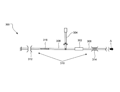
3 shows a schematic view of an example rotorcraft autopilot
system 300. The example rotorcraft autopilot system 300 includes a series
actuator
302 connecting a cockpit control component 304 (e.g., cyclic controller 109
and/or
pedals 111 of FIG. 1) to a swashplate of a rotorcraft. In some
implementations, the
series actuator 302 connects the cockpit control component 304 to an anti-
torque
is system of a
rotorcraft. Under non-trimming conditions of the rotorcraft autopilot
system 300, the series actuator 302 transmits a control input from the cockpit
control
component 304 to the swashplate through a downstream control component 306.
The series actuator 302 modifies (e.g., dampens, delays, amplifies,
stabilizes, and/or
otherwise transmits) the control input from the cockpit control component 304
to the
20 swashplate
through a downstream control component 306, as illustrated by arrow A.
In some implementations, the series actuator 302 modifies the control input by
adjusting a movement between an upstream control component 308 connected to
the
cockpit control component 304 and the downstream control component 306 to move
the swashplate in response to the control input from the cockpit control
component
25 304 and/or
inputs from rotorcraft motion sensors. An example control input may
include a hands-on input from a pilot of the rotorcraft to move the cockpit
control
component 304. In some instances, a control input on the cockpit control
component
304 causes the swashplate to move via movement of the upstream control
component 308 against the series actuator 302, and movement of the series
actuator
30 302 against
the downstream control component 306 directly or indirectly attached to
the swashplate. For
example, under non-trimming conditions of the rotorcraft
autopilot system 300, the series actuator 302 connects the upstream control
component 308 with the downstream control component 306 as a substantially
rigid
link, but may supply differential motions to the downstream control component
306
35 without
moving the upstream control component 308. In some implementations, the
series actuator 302 includes a control tube
5
CA 02901482 2015-08-21
connecting the upstream control component 308 with the downstream control
component 306. For example, the series actuator 302 moves the upstream control
component 308 and/or the downstream control component 306 such that a gap
between the upstream control component 308 and the downstream control
component 306 within the control tube is centered in the control tube of the
series
actuator 302.
[0021] The example rotorcraft autopilot system 300 also includes a
differential
friction system 310 connected to the cockpit control component 304 to control
the
series actuator 302 to automatically adjust a position of the cockpit control
component
to 304 during rotorcraft flight based, in part, on a flight mode of the
rotorcraft. For
example, a transition in flight mode between a hover mode to a cruise flight
mode
may require a change in cockpit control component 304 position. The
differential
friction system 310 of the example rotorcraft autopilot system 300 includes a
clutch
brake 312 grounded to the rotorcraft proximate the upstream control component
308
and a variable friction device 314 grounded to the rotorcraft proximate the
downstream control component 306. The clutch brake 312 can engage or disengage
the upstream control component 308, for example, to prevent movement of the
upstream control component 308 or allow movement of the upstream control
component 308, respectively. The clutch brake 312 can take many forms. For
zo example, the clutch brake 312 can include a magnetic clutch brake,
and/or another
brake. The clutch brake 312 can engage the upstream control component 308 at a
variety of positions of the upstream control component 308. For example, the
clutch
brake 312 can engage and prevent movement of the upstream control component
308 in the position depicted in FIG. 3, where the cockpit control component
304 is at a
center position. In another example, the clutch brake 312 can engage and
prevent
movement of the upstream control component 308 in a different position than
depicted in FIG. 3 after the upstream control component 308 is moved in
response to
a control input on the cockpit control component 304 and/or actuation of the
series
actuator 302. In certain implementations, the clutch brake 312 provides a
frictional
slippage between the upstream control component 308 and a rotorcraft
structure.
[0022] The variable friction device 314 can selectively increase or decrease
friction on the downstream control component 306, for example, to
(substantially or
wholly) prevent movement of the downstream control component 306 or
substantially
allow movement of the downstream control component 306, respectively. In some
implementations, the variable friction device 314 can provide additional or
different
6
CA 02901482 2015-08-21
features. For example, the variable friction device 314 can apply a variable
friction or
a fixed friction on the downstream control component 306, or selectively not
apply
friction on the downstream control component 306. In certain implementations,
the
variable friction device 314 is excluded from the example rotorcraft autopilot
system
300, and a fixed friction (e.g., natural friction) of the downstream control
component
306 substantially prevents movement of the downstream control component 306,
for
example, while the clutch brake 312 is disengaged from the upstream control
component 308. Alternatively, the fixed friction of the downstream control
component
306 substantially allows movement of the downstream control component 306, for
example, while the clutch brake 312 is engaged with the upstream control
component
308. In some implementations, the fixed friction of the downstream control
component 306 corresponds to downstream joint stiffness, a spring force at
downstream joints, and/or other friction sources.
[0023] In some examples, the series actuator 302 may be limited in
mechanical authority for fail safety reasons to 10% to 20% of full control
authority. A
transition in flight mode, for example, between a hover mode and a cruise
flight mode,
may require a change in cockpit control component 304 position by 50% or more.
In
some implementations, the differential friction system 310 allows automatic
movement
of the cockpit control component 304 as needed to keep the series actuator 302
operating within its mechanical authority limits by selectively switching
between
trimming and non-trimming conditions. For example, referring to FIG. 7, a flow
chart
describing an example process 700 performed by the differential friction
system 310
of FIG. 3 is described. At 702, the variable friction device 314 is disengaged
and the
clutch brake 312 is engaged. At 704, a flight mode is determined. At 706, the
series
actuator 302 actuates toward a position corresponding to the determined flight
mode.
At 708, if a position of the series actuator 302 exceeds a mechanical
authority
threshold for a given time period, the variable friction device 314 engages,
the clutch
brake 312 disengages, and the series actuator 302 recenters.
[0024] Referring back to FIG. 3, in some implementations, the rotorcraft
autopilot system 300 includes a centering spring 316, for example, a double
acting
spring cartridge, on the upstream control component 308 between the clutch
brake
312 and the cockpit control component 304 to bias the cockpit control
component 304
towards a neutral center position when the clutch brake 312 is engaged. The
neutral
center position of the cockpit control component 304 corresponds with the
position of
the upstream control component 308 when the clutch brake 312 is engaged.
7
CA 02901482 2015-08-21
Although FIG. 3 shows the neutral center position of the cockpit control
component
304 as substantially vertical, a neutral center position of the cockpit
control
component 304 can be offset from the vertical. In some implementations, under
non-
trimming conditions (e.g., when the clutch brake 312 is engaged), the
centering spring
316 provides a force-feel for a pilot applying force on the cockpit control
component
304 due to compression or extension of the centering spring 316. In some
implementations, the downstream control component 306 and the upstream control
component 308 include a downstream control linkage and an upstream control
linkage, respectively. The upstream control component 308 can include a joint
in the
io upstream linkage that pivotly connects to the cockpit control component
304.
Although FIG. 3 shows the joint as a pivot joint, the rotorcraft autopilot
system 300
can be implemented in more than one spatial axis, for example, where the joint
is a
universal joint to effect multi-axis movement. The example upstream control
component 308 of FIG. 3 shows one upstream linkage extending from the series
actuator 302 to the clutch brake 312 with a joint connecting to the cockpit
control
component 304. However, in some implementations, the upstream control
component 308 includes more than one upstream linkage. The example downstream
control component 306 of FIG. 3 shows one downstream linkage extending from
the
series actuator 302 toward the swashplate. However, the downstream control
component 306 can include more than one downstream linkage that can connect
directly or indirectly to the swashplate of the rotorcraft.
[0025] In some implementations, a rotorcraft with the example autopilot
system 300 trims the cockpit control component 304 to match a swashplate
position
for a specified flight mode of the rotorcraft. The specified flight mode can
include
hover mode, takeoff, climbout, cruise, turning, descent, approach, a
combination of
this list, and/or another rotorcraft flight mode. The series actuator 302
effects
movement of the swashplate and/or the cockpit control component 304 based on a
differential friction across the series actuator 302. In other words,
actuation of the
series actuator 302 moves the cockpit control component 304 at a first
differential
friction, and moves the swashplate at a second differential friction across
the series
actuator 302. In some instances, the differential friction system 310 adjusts
the
differential friction across the series actuator 302. For example, disengaging
the
clutch brake 312 on the upstream control component 308 allows movement of the
upstream control component 308. In some examples, increasing friction on the
downstream control component 306 by the variable friction device 314
(substantially
or wholly) prevents movement of the downstream control component 306. Thus,
8
CA 02901482 2015-08-21
actuation (e.g., internal centering) of the series actuator 302 moves the
upstream
control component 306, and therefore moves the cockpit control component 304,
for
example, to a cockpit control position corresponding to the swashplate
position for the
specified flight mode of the rotorcraft. Disengaging the clutch brake 312 and
increasing friction of the variable friction device 314 creates the first
differential friction
across the series actuator 302. In certain instances, the variable friction
device 314
intermittently decreases friction on the downstream control component 306 to
allow
movement of the downstream control component 306, and the clutch brake engages
to prevent movement of the upstream control component 308 to allow the series
o actuator 302 to move the swashplate, for example, when a pilot provides
intermittent
hands-on control of the cockpit control component 304. Engaging the clutch
brake
312 and decreasing friction of the variable friction device 314 creates the
second
differential friction across the series actuator 302.
[0026] In some implementations, the differential friction across the series
is actuator 302 is defined by a friction applied on the upstream control
component 308
compared to a friction applied on the downstream control component 306. In
other
words, a higher friction on the upstream component 308 than a lower friction
on the
downstream component 306 allows the series actuator 302 to (substantially or
wholly)
move the downstream component 306 without (substantially or wholly) moving the
20 upstream component 308. For example, when the clutch brake 312 is
engaged, the
series actuator 302 actuates to move the downstream control component 306, and
subsequently move the swashplate, while the upstream component 308 does not
move. Alternatively, a higher friction on the downstream component 306 than a
lower
friction on the upstream component 308 allows the series actuator 302 to
25 (substantially or wholly) move the upstream component 308 without
(substantially or
wholly) moving the downstream component 306. For example,
when the clutch
brake 312 is disengaged, the series actuator 302 actuates to move the upstream
control component 308, and subsequently move the cockpit control component
304,
while the downstream control component 306 does not move due to a fixed
friction in
30 the downstream component 306 being greater than that of the upstream
component
308 and/or due to the variable friction device 314 applying a higher friction
on the
downstream control component 306 than that of the upstream control component
308.
[0027] A rotorcraft autopilot system can take many forms, and can be
implemented in a manner different than the rotorcraft autopilot system 300 of
FIG. 3.
35 For example, FIG. 4 shows an example rotorcraft autopilot system 400
that is like the
9
CA 02901482 2015-08-21
rotorcraft autopilot system 300 of FIG. 3, except the differential friction
system 410 is
implemented differently, including the clutch brake 412 and the variable
friction device
414. In the example rotorcraft autopilot system 400 of FIG. 4, the clutch
brake 412,
series actuator 302, and variable friction device 414 are adjacent each other,
with the
clutch brake 412 connected to the upstream control component 308 proximate an
upstream end of the series actuator 302 and the variable friction device 414
connected to the downstream control component 306 proximate a downstream end
of
the series actuator 302. The clutch brake 412 can selectively ground to the
rotorcraft
to prevent movement of the upstream control component 308, while allowing the
series actuator 302 to actuate and move the downstream control component 306.
The variable friction device 414 can selectively ground to the rotorcraft to
prevent
movement of the downstream control component 306, while allowing the series
actuator 302 to actuate and move the upstream control component 308. In
certain
implementations, the clutch brake 412, series actuator 302, and variable
friction
device 414 can comprise a single variable actuator assembly that connects on
one
end to the upstream control component 308 and on another end to the downstream
control component 306, where the clutch brake 412 and the variable friction
device
414 can selectively ground to the rotorcraft and prevent movement of the
upstream
control component 308 and the downstream control component 306, respectively.
For example, under non-trimming conditions, the clutch brake 412 is engaged
with the
upstream control component 308 and grounded to the rotorcraft to prevent
movement
of the upstream control component 308, while allowing the series actuator 302
to
actuate the downstream control component 306 as needed.
[0028] In some implementations, the autopilot system includes a controller to
control operations of the series actuator, clutch brake, variable friction
device, and/or
other components of the autopilot system. The controller can be implemented as
processing circuitry (e.g., hardware, firmware, and/or other) that may or may
not
connect to other processing circuitry of the rotorcraft.
[0029] FIG. 5 is a flow chart describing a method 500 for controlling
rotorcraft
flight, for example, performed by the example rotorcraft autopilot system 300
or 400.
At 502, a flight mode of a rotorcraft is determined. At 504, a swashplate
position of
the rotorcraft corresponding to the determined flight mode is identified. At
506, a
cockpit control position of a rotorcraft cockpit control component is adjusted
based on
a differential friction across a series actuator connecting the cockpit
control
CA 02901482 2015-08-21
component to the swashplate. The adjusted cockpit control position matches the
identified swashplate position.
[0030] FIG. 6 is a flow chart describing another method 600 for controlling
rotorcraft flight, for example, performed by the example rotorcraft autopilot
system 300
or 400. At 602, a differential friction between an upstream linkage and a
downstream
linkage relative to a series actuator is adjusted to allow movement of the
upstream
linkage and prevent movement of the downstream linkage. At 604, actuation of
the
series actuator is controlled in response to the adjusted differential
friction between
the upstream linkage and the downstream linkage.
io [0031] A number
of implementations have been described. Nevertheless, it
will be understood that various modifications may be made without departing
from the
spirit and scope of the disclosure.
11