Language selection

Search

Patent 2901620 Summary

Third-party information liability

Some of the information on this Web page has been provided by external sources. The Government of Canada is not responsible for the accuracy, reliability or currency of the information supplied by external sources. Users wishing to rely upon this information should consult directly with the source of the information. Content provided by external sources is not subject to official languages, privacy and accessibility requirements.

Claims and Abstract availability

Any discrepancies in the text and image of the Claims and Abstract are due to differing posting times. Text of the Claims and Abstract are posted:

  • At the time the application is open to public inspection;
  • At the time of issue of the patent (grant).
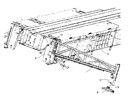
(12) Patent: (11) CA 2901620
(54) English Title: SYSTEM FOR ATTACHING A GULLWING TO A CATWALK
(54) French Title: SYSTEME POUR ATTACHER UNE AILE DE SUPPORT A UNE PASSERELLE
Status: Expired and beyond the Period of Reversal
Bibliographic Data
(51) International Patent Classification (IPC):
  • E21B 19/14 (2006.01)
(72) Inventors :
  • SWANSON, GREGORY DAVID (United States of America)
  • RAMIREZ, ALEXANDRO ROMAN (United States of America)
(73) Owners :
  • FORUM US, INC.
(71) Applicants :
  • FORUM US, INC. (United States of America)
(74) Agent: NATHAN V. WOODRUFFWOODRUFF, NATHAN V.
(74) Associate agent:
(45) Issued: 2017-01-03
(86) PCT Filing Date: 2014-03-13
(87) Open to Public Inspection: 2014-10-02
Examination requested: 2015-08-17
Availability of licence: N/A
Dedicated to the Public: N/A
(25) Language of filing: English

Patent Cooperation Treaty (PCT): Yes
(86) PCT Filing Number: PCT/US2014/025725
(87) International Publication Number: WO 2014160056
(85) National Entry: 2015-08-17

(30) Application Priority Data:
Application No. Country/Territory Date
61/780,588 (United States of America) 2013-03-13

Abstracts

English Abstract

A system for connecting a gullwing to a catwalk comprising a gullwing pin movable in an indexer groove that enables a foot pad of the gullwing to remain stationary relative to the catwalk when the gullwing is raised or lowered.


French Abstract

L'invention porte sur un système pour relier une aile de support à une passerelle, lequel système comprend une broche d'aile de support mobile dans une rainure d'indexeur qui permet à une zone de pied de l'aile de support de rester stationnaire par rapport à la passerelle quand l'aile de support est élevée ou abaissée.

Claims

Note: Claims are shown in the official language in which they were submitted.

Claims:
1. A system for attaching a gullwing to a catwalk, comprising:
a gullwing coupled to a catwalk via an indexer unit;
a pin coupled to a knuckle of the gullwing and positioned within a slot formed
in the indexer unit, wherein the pin moves within the slot in a direction
toward the
catwalk when the gullwing is raised relative to the catwalk.
2. The system of claim 1, wherein the pin moves in a substantially
horizontal
direction within the slot toward the catwalk when the gullwing is raised
relative to the
catwalk.
3. The system of claim 1, wherein the knuckle is movable relative to the
indexer
unit when the pin moves within the slot formed in the indexer unit.
4. The system of claim 3, wherein the pin is disposed through the knuckle
such
that portions of the pin extend from opposite sides of the knuckle, and
wherein the
portions of the pin are positioned within the slot formed in the indexer unit.
5. The system of claim 1, wherein a foot pad coupled to the gullwing
remains
substantially stationary relative to the catwalk when the gullwing is raised
or lowered.
6. The system of claim 5, wherein a hydraulic cylinder raises the gullwing
by
extending a rod against the foot pad.
7. The system of claim 6, wherein the indexer unit includes an indexer pin
configured to support a section of pipe that is transferred by the gullwing
when the
gullwing is raised relative to the catwalk.
8. A method of attaching a gullwing to a catwalk, comprising:
coupling a pin to a knuckle of the gullwing; and
inserting the pin into a slot formed in an indexer unit that is coupled to the
catwalk to attach the gullwing to the catwalk, wherein the pin moves within
the slot in
a direction toward the catwalk when the gullwing is raised relative to the
catwalk.

9. The method of claim 8, wherein the pin moves in a substantially
horizontal
direction within the slot toward the catwalk when the gullwing is raised
relative to the
catwalk.
10. The method of claim 8, wherein the knuckle is movable relative to the
indexer
unit when the pin moves within the slot formed in the indexer unit.
11. The method of claim 10, wherein the pin is disposed through the knuckle
such
that portions of the pin extend from opposite sides of the knuckle, and
wherein the
portions of the pin are positioned within the slot formed in the indexer unit.
12. The method of claim 8, wherein a foot pad coupled to the gullwing
remains
substantially stationary relative to the catwalk when the gullwing is raised
or lowered.
13. The method of claim 12, further comprising raising the gullwing
relative to the
catwalk by extending a rod from a hydraulic cylinder against the foot pad.
14. The method of claim 13, further comprising supporting a section of pipe
using
an indexer pin of the indexer unit, wherein the section of pipe is transferred
by the
gullwing when the gullwing is raised relative to the catwalk.
15. A system for attaching a gullwing to a catwalk, comprising:
a gullwing pin supported by the gullwing;
a groove in an indexer coupled to the catwalk, wherein the gullwing pin moves
within the groove in a direction toward the catwalk when the gullwing is
raised
relative to the catwalk.
16. The system of claim 15, wherein a foot pad coupled to the gullwing
remains
substantially stationary relative to the catwalk when the gullwing is raised
or lowered.
6

Description

Note: Descriptions are shown in the official language in which they were submitted.


CA 02901620 2015-08-17
WO 2014/160056 PCT/US2014/025725
SYSTEM FOR ATTACHING A GULLWING TO A CATWALK
BACKGROUND OF THE INVENTION
Field of the Invention
[0001] Embodiments of the invention generally relate to catwalks for conveying
pipe
to a drill floor from a lower section of a drilling rig or drill site.
Specifically,
embodiments of the invention relate to an apparatus for attaching a "gullwing"
to the
catwalk so that the gullwing pad will not move toward and away from the
catwalk as
the gullwing is raised and lowered during the conveying of pipe to the catwalk
trough.
Description of the Related Art
[0002] In a drilling operation or rig work-over operation, whether on a water-
based or
land-based drilling rig, pipe for the drilling operation, casing, or other
tubulars are
often stored at or supplied from a level that is lower than the drill floor.
Operators
typically use a "catwalk" to convey the pipe from the lower level to the drill
floor. The
pipe is typically mechanically transported (e.g. pushed and/or pulled) in a v-
shaped
trough, from a level below the rig floor to the rig floor.
[0003] Before they are positioned in the catwalk trough and transported to the
drill
floor, multiple sections of pipe or other tubulars can be positioned on
multiple
"gullwings" positioned adjacent to the catwalk. The ends of the gullwings
positioned
away from the catwalk are hydraulically raised to create a slope in the
direction of
the catwalk and trough. Prior art components known as indexers cause a single
section of pipe to roll to the trough.
[0004] One problem with existing gullwings is that the pads for the gullwing
feet will
shift away from the catwalk when the gullwing is raised, and will shift toward
the
catwalk when the gullwing is lowered. This creates a potentially dangerous
situation
in that the sliding pads could potentially injure workers working nearby, wear
down
the ground below the gullwing (thus causing the pipe to be stored in an uneven
position), or wear out the feet pads. Accordingly, it would be useful to have
a system
for connecting the gullwing to the catwalk which would minimize the movement
of the
gullwing pads when the gullwing is raised and lowered.
1

CA 02901620 2015-08-17
WO 2014/160056 PCT/US2014/025725
SUMMARY OF THE INVENTION
[0005] Embodiments of the invention provide a system for connecting a gullwing
to a
catwalk in which a gullwing pin is allowed to move in relation to the
connection point
in the catwalk instead of causing a gullwing foot pad to move relative to the
ground.
The system also allows for the quick removal of the gullwing from the catwalk
by
lifting the gullwing vertical relative to the catwalk.
BRIEF DESCRIPTION OF THE DRAWINGS
[0006] So that the manner in which the above recited aspects of the invention
can
be understood in detail, a more particular description of embodiments of the
invention, briefly summarized above, may be had by reference to embodiments,
some of which are illustrated in the appended drawings. It is to be noted,
however,
that the appended drawings illustrate only typical embodiments of this
invention and
are therefore not to be considered limiting of its scope, for the invention
may admit to
other equally effective embodiments.
[0007] Figure 1A shows a catwalk in the position in which pipe is loaded onto
the
catwalk or unloaded from the catwalk.
[0008] Figure 1 B shows the catwalk in an elevated position in which pipe is
being
conveyed to or from the drill floor.
[0009] Figure 2 shows a cross section of a catwalk where a gullwing is
connected to
an indexer module for the catwalk and, at the opposite end of the gullwing, a
hydraulic cylinder that pushes against a pad to lower one side of the
gullwing.
[oolo] Figure 3 shows the hydraulic cylinder and pad illustrated in Figure 2.
[0011] Figure 4 is a closer view of the end of the gullwing connected to the
catwalk.
[0012] Figure 5 is a cut-away view of a gullwing pin in a pin slot in the
catwalk.
[0013] Figure 6 is a top view of the pin slot.
[0014] Figure 7 is a view of the gullwing pin position adjacent to a top
knuckle of the
gullwing.
2

CA 02901620 2015-08-17
WO 2014/160056 PCT/US2014/025725
DETAILED DESCRIPTION
[0015] Figure 1A shows gullwings 1 and 2 attached to catwalk 3. Sections of
pipe
are positioned on gullwings 1 and 2. Gullwings 1 and 2 are raised temporarily
using
hydraulics to allow a section of pipe to roll onto catwalk 3 and into trough
4. The
pipe is then conveyed to the drill center on a higher level drill floor using
skate 5 as
the catwalk 3 is raised to a position shown in Figure 1 B.
[0016] Figure 2 shows a cross section of catwalk 3 and trough 4 where gullwing
1 is
connected to catwalk 3 via indexer unit 6. The connection of gullwing 2 to
catwalk 3
is identical. Hydraulic cylinder 7 is positioned on gullwing foot pad 8.
Hydraulic
cylinder 7 raises and lowers gullwing 1 by extending rod 9 against foot pad 8
as
known in prior art systems. Gullwing pin 10, which is positioned in slot 11 in
indexer
unit 6, slides back and forth in slot 11 as gullwing 1 is raised and lowered
by
hydraulic cylinder 7, allowing gullwing foot pad 8 to remain relatively still.
[0017] Figure 3 is a detailed view of hydraulic cylinder 7 attached to
gullwing 1.
Hydraulic cylinder 7 raises gullwing 1 by extending rod 9 against foot pad 8.
[0018] Figure 4 is a detailed view of gullwing 1 and gullwing pin 10 in slot
11. Pin 10
is shown in a position when pipe is not being moved toward trough 4. When
gullwing
1 is raised, pin 10 moves toward point 11A in slot 11 (e.g. in a lateral,
substantially
horizontal direction toward the catwalk 3). The gullwing 1 may support
multiple
sections of pipe when raised. At least one section of pipe rests against
indexer pin
12. Another indexer pushes the section of pipe over indexer pin 12, and that
section
of pipe rolls toward trough 4. When the indexer is retracted, the next section
of pipe
comes to rest against indexer pin 12. After all of the pipe sections have has
passed
indexer pin 12, gullwing 1 is lowered and pin 10 returns to its position shown
in
Figure 4.
[0019] Figure 5 is a detailed view of pin 10 in slot 11. Pin 10 moves toward
point
11A in slot 11 when gullwing 1 is raised. Gullwing knuckle 13 similarly moves
toward
section 11 B of slot 11 when gullwing 1 is raised. As a result of the movement
of pin
and knuckle 13, foot pad 8 shown in Figures 2 and 3 stays relatively
stationary.
[0020] Figure 6 is a top view of slot 11. Areas 110 and 11 D are the portions
of slot
11 in which the pin 10 on the opposite side of knuckle 13 are inserted.
Section 11B
3

CA 02901620 2015-08-17
WO 2014/160056 PCT/US2014/025725
is space for knuckle 13 to move into when gullwing 1 is raised and pin 10
moves
within slot 11.
[0021] Figure 7 is a top view of gullwing pin 10 positioned in gullwing 1
below
gullwing knuckle 13. Bushing 14A is positioned in a hole below gullwing
knuckle 13
and along with another bushing in a hole on the opposite side of the gullwing
allows
pin 10 to rotate within the holes as the gullwing 1 is moved up and down. This
allows the pin 10 and knuckle 13 to move back and forth in slot 11 as
described in
reference to Figs. 4, 5, and 6.
[0022] While the foregoing is directed to embodiments of the invention, other
and
further embodiments of the invention may be devised without departing from the
basic scope thereof, and the scope thereof is determined by the claims that
follow.
4

Representative Drawing
A single figure which represents the drawing illustrating the invention.
Administrative Status

2024-08-01:As part of the Next Generation Patents (NGP) transition, the Canadian Patents Database (CPD) now contains a more detailed Event History, which replicates the Event Log of our new back-office solution.

Please note that "Inactive:" events refers to events no longer in use in our new back-office solution.

For a clearer understanding of the status of the application/patent presented on this page, the site Disclaimer , as well as the definitions for Patent , Event History , Maintenance Fee  and Payment History  should be consulted.

Event History

Description Date
Time Limit for Reversal Expired 2020-03-13
Common Representative Appointed 2019-10-30
Letter Sent 2019-03-13
Letter Sent 2017-11-22
Inactive: Multiple transfers 2017-11-08
Grant by Issuance 2017-01-03
Inactive: Cover page published 2017-01-02
Pre-grant 2016-11-22
Inactive: Final fee received 2016-11-22
Notice of Allowance is Issued 2016-05-31
Letter Sent 2016-05-31
Inactive: Approved for allowance (AFA) 2016-05-24
Inactive: Q2 passed 2016-05-24
Inactive: Cover page published 2015-09-14
Inactive: IPC assigned 2015-08-28
Application Received - PCT 2015-08-28
Inactive: First IPC assigned 2015-08-28
Letter Sent 2015-08-28
Inactive: Acknowledgment of national entry - RFE 2015-08-28
All Requirements for Examination Determined Compliant 2015-08-17
National Entry Requirements Determined Compliant 2015-08-17
Request for Examination Requirements Determined Compliant 2015-08-17
Application Published (Open to Public Inspection) 2014-10-02

Abandonment History

There is no abandonment history.

Maintenance Fee

The last payment was received on 2016-12-16

Note : If the full payment has not been received on or before the date indicated, a further fee may be required which may be one of the following

  • the reinstatement fee;
  • the late payment fee; or
  • additional fee to reverse deemed expiry.

Please refer to the CIPO Patent Fees web page to see all current fee amounts.

Fee History

Fee Type Anniversary Year Due Date Paid Date
Request for examination - standard 2015-08-17
MF (application, 2nd anniv.) - standard 02 2016-03-14 2015-08-17
Basic national fee - standard 2015-08-17
Final fee - standard 2016-11-22
MF (application, 3rd anniv.) - standard 03 2017-03-13 2016-12-16
Registration of a document 2017-11-08
MF (patent, 4th anniv.) - standard 2018-03-13 2018-02-13
Owners on Record

Note: Records showing the ownership history in alphabetical order.

Current Owners on Record
FORUM US, INC.
Past Owners on Record
ALEXANDRO ROMAN RAMIREZ
GREGORY DAVID SWANSON
Past Owners that do not appear in the "Owners on Record" listing will appear in other documentation within the application.
Documents

To view selected files, please enter reCAPTCHA code :


To view images, click a link in the Document Description column. To download the documents, select one or more checkboxes in the first column and then click the "Download Selected in PDF format (Zip Archive)" or the "Download Selected as Single PDF" button.

List of published and non-published patent-specific documents on the CPD .

If you have any difficulty accessing content, you can call the Client Service Centre at 1-866-997-1936 or send them an e-mail at CIPO Client Service Centre.


Document
Description 
Date
(yyyy-mm-dd) 
Number of pages   Size of Image (KB) 
Representative drawing 2015-08-17 1 110
Drawings 2015-08-17 8 390
Description 2015-08-17 4 159
Claims 2015-08-17 2 74
Abstract 2015-08-17 1 97
Cover Page 2015-09-14 1 87
Representative drawing 2016-12-15 1 71
Cover Page 2016-12-15 1 96
Acknowledgement of Request for Examination 2015-08-28 1 176
Notice of National Entry 2015-08-28 1 202
Commissioner's Notice - Application Found Allowable 2016-05-31 1 163
Maintenance Fee Notice 2019-04-24 1 180
National entry request 2015-08-17 3 106
International search report 2015-08-17 1 55
Patent cooperation treaty (PCT) 2015-08-17 1 41
Final fee 2016-11-22 1 33