Sélection de la langue

Search

Sommaire du brevet 2901620 

Énoncé de désistement de responsabilité concernant l'information provenant de tiers

Une partie des informations de ce site Web a été fournie par des sources externes. Le gouvernement du Canada n'assume aucune responsabilité concernant la précision, l'actualité ou la fiabilité des informations fournies par les sources externes. Les utilisateurs qui désirent employer cette information devraient consulter directement la source des informations. Le contenu fourni par les sources externes n'est pas assujetti aux exigences sur les langues officielles, la protection des renseignements personnels et l'accessibilité.

Disponibilité de l'Abrégé et des Revendications

L'apparition de différences dans le texte et l'image des Revendications et de l'Abrégé dépend du moment auquel le document est publié. Les textes des Revendications et de l'Abrégé sont affichés :

  • lorsque la demande peut être examinée par le public;
  • lorsque le brevet est émis (délivrance).
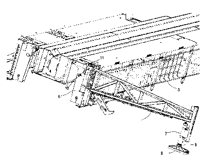
(12) Brevet: (11) CA 2901620
(54) Titre français: SYSTEME POUR ATTACHER UNE AILE DE SUPPORT A UNE PASSERELLE
(54) Titre anglais: SYSTEM FOR ATTACHING A GULLWING TO A CATWALK
Statut: Périmé et au-delà du délai pour l’annulation
Données bibliographiques
(51) Classification internationale des brevets (CIB):
  • E21B 19/14 (2006.01)
(72) Inventeurs :
  • SWANSON, GREGORY DAVID (Etats-Unis d'Amérique)
  • RAMIREZ, ALEXANDRO ROMAN (Etats-Unis d'Amérique)
(73) Titulaires :
  • FORUM US, INC.
(71) Demandeurs :
  • FORUM US, INC. (Etats-Unis d'Amérique)
(74) Agent: NATHAN V. WOODRUFFWOODRUFF, NATHAN V.
(74) Co-agent:
(45) Délivré: 2017-01-03
(86) Date de dépôt PCT: 2014-03-13
(87) Mise à la disponibilité du public: 2014-10-02
Requête d'examen: 2015-08-17
Licence disponible: S.O.
Cédé au domaine public: S.O.
(25) Langue des documents déposés: Anglais

Traité de coopération en matière de brevets (PCT): Oui
(86) Numéro de la demande PCT: PCT/US2014/025725
(87) Numéro de publication internationale PCT: WO 2014160056
(85) Entrée nationale: 2015-08-17

(30) Données de priorité de la demande:
Numéro de la demande Pays / territoire Date
61/780,588 (Etats-Unis d'Amérique) 2013-03-13

Abrégés

Abrégé français

L'invention porte sur un système pour relier une aile de support à une passerelle, lequel système comprend une broche d'aile de support mobile dans une rainure d'indexeur qui permet à une zone de pied de l'aile de support de rester stationnaire par rapport à la passerelle quand l'aile de support est élevée ou abaissée.


Abrégé anglais

A system for connecting a gullwing to a catwalk comprising a gullwing pin movable in an indexer groove that enables a foot pad of the gullwing to remain stationary relative to the catwalk when the gullwing is raised or lowered.

Revendications

Note : Les revendications sont présentées dans la langue officielle dans laquelle elles ont été soumises.


Claims:
1. A system for attaching a gullwing to a catwalk, comprising:
a gullwing coupled to a catwalk via an indexer unit;
a pin coupled to a knuckle of the gullwing and positioned within a slot formed
in the indexer unit, wherein the pin moves within the slot in a direction
toward the
catwalk when the gullwing is raised relative to the catwalk.
2. The system of claim 1, wherein the pin moves in a substantially
horizontal
direction within the slot toward the catwalk when the gullwing is raised
relative to the
catwalk.
3. The system of claim 1, wherein the knuckle is movable relative to the
indexer
unit when the pin moves within the slot formed in the indexer unit.
4. The system of claim 3, wherein the pin is disposed through the knuckle
such
that portions of the pin extend from opposite sides of the knuckle, and
wherein the
portions of the pin are positioned within the slot formed in the indexer unit.
5. The system of claim 1, wherein a foot pad coupled to the gullwing
remains
substantially stationary relative to the catwalk when the gullwing is raised
or lowered.
6. The system of claim 5, wherein a hydraulic cylinder raises the gullwing
by
extending a rod against the foot pad.
7. The system of claim 6, wherein the indexer unit includes an indexer pin
configured to support a section of pipe that is transferred by the gullwing
when the
gullwing is raised relative to the catwalk.
8. A method of attaching a gullwing to a catwalk, comprising:
coupling a pin to a knuckle of the gullwing; and
inserting the pin into a slot formed in an indexer unit that is coupled to the
catwalk to attach the gullwing to the catwalk, wherein the pin moves within
the slot in
a direction toward the catwalk when the gullwing is raised relative to the
catwalk.

9. The method of claim 8, wherein the pin moves in a substantially
horizontal
direction within the slot toward the catwalk when the gullwing is raised
relative to the
catwalk.
10. The method of claim 8, wherein the knuckle is movable relative to the
indexer
unit when the pin moves within the slot formed in the indexer unit.
11. The method of claim 10, wherein the pin is disposed through the knuckle
such
that portions of the pin extend from opposite sides of the knuckle, and
wherein the
portions of the pin are positioned within the slot formed in the indexer unit.
12. The method of claim 8, wherein a foot pad coupled to the gullwing
remains
substantially stationary relative to the catwalk when the gullwing is raised
or lowered.
13. The method of claim 12, further comprising raising the gullwing
relative to the
catwalk by extending a rod from a hydraulic cylinder against the foot pad.
14. The method of claim 13, further comprising supporting a section of pipe
using
an indexer pin of the indexer unit, wherein the section of pipe is transferred
by the
gullwing when the gullwing is raised relative to the catwalk.
15. A system for attaching a gullwing to a catwalk, comprising:
a gullwing pin supported by the gullwing;
a groove in an indexer coupled to the catwalk, wherein the gullwing pin moves
within the groove in a direction toward the catwalk when the gullwing is
raised
relative to the catwalk.
16. The system of claim 15, wherein a foot pad coupled to the gullwing
remains
substantially stationary relative to the catwalk when the gullwing is raised
or lowered.
6

Description

Note : Les descriptions sont présentées dans la langue officielle dans laquelle elles ont été soumises.

CA 02901620 2015-08-17
WO 2014/160056 PCT/US2014/025725
SYSTEM FOR ATTACHING A GULLWING TO A CATWALK
BACKGROUND OF THE INVENTION
Field of the Invention
[0001] Embodiments of the invention generally relate to catwalks for conveying
pipe
to a drill floor from a lower section of a drilling rig or drill site.
Specifically,
embodiments of the invention relate to an apparatus for attaching a "gullwing"
to the
catwalk so that the gullwing pad will not move toward and away from the
catwalk as
the gullwing is raised and lowered during the conveying of pipe to the catwalk
trough.
Description of the Related Art
[0002] In a drilling operation or rig work-over operation, whether on a water-
based or
land-based drilling rig, pipe for the drilling operation, casing, or other
tubulars are
often stored at or supplied from a level that is lower than the drill floor.
Operators
typically use a "catwalk" to convey the pipe from the lower level to the drill
floor. The
pipe is typically mechanically transported (e.g. pushed and/or pulled) in a v-
shaped
trough, from a level below the rig floor to the rig floor.
[0003] Before they are positioned in the catwalk trough and transported to the
drill
floor, multiple sections of pipe or other tubulars can be positioned on
multiple
"gullwings" positioned adjacent to the catwalk. The ends of the gullwings
positioned
away from the catwalk are hydraulically raised to create a slope in the
direction of
the catwalk and trough. Prior art components known as indexers cause a single
section of pipe to roll to the trough.
[0004] One problem with existing gullwings is that the pads for the gullwing
feet will
shift away from the catwalk when the gullwing is raised, and will shift toward
the
catwalk when the gullwing is lowered. This creates a potentially dangerous
situation
in that the sliding pads could potentially injure workers working nearby, wear
down
the ground below the gullwing (thus causing the pipe to be stored in an uneven
position), or wear out the feet pads. Accordingly, it would be useful to have
a system
for connecting the gullwing to the catwalk which would minimize the movement
of the
gullwing pads when the gullwing is raised and lowered.
1

CA 02901620 2015-08-17
WO 2014/160056 PCT/US2014/025725
SUMMARY OF THE INVENTION
[0005] Embodiments of the invention provide a system for connecting a gullwing
to a
catwalk in which a gullwing pin is allowed to move in relation to the
connection point
in the catwalk instead of causing a gullwing foot pad to move relative to the
ground.
The system also allows for the quick removal of the gullwing from the catwalk
by
lifting the gullwing vertical relative to the catwalk.
BRIEF DESCRIPTION OF THE DRAWINGS
[0006] So that the manner in which the above recited aspects of the invention
can
be understood in detail, a more particular description of embodiments of the
invention, briefly summarized above, may be had by reference to embodiments,
some of which are illustrated in the appended drawings. It is to be noted,
however,
that the appended drawings illustrate only typical embodiments of this
invention and
are therefore not to be considered limiting of its scope, for the invention
may admit to
other equally effective embodiments.
[0007] Figure 1A shows a catwalk in the position in which pipe is loaded onto
the
catwalk or unloaded from the catwalk.
[0008] Figure 1 B shows the catwalk in an elevated position in which pipe is
being
conveyed to or from the drill floor.
[0009] Figure 2 shows a cross section of a catwalk where a gullwing is
connected to
an indexer module for the catwalk and, at the opposite end of the gullwing, a
hydraulic cylinder that pushes against a pad to lower one side of the
gullwing.
[oolo] Figure 3 shows the hydraulic cylinder and pad illustrated in Figure 2.
[0011] Figure 4 is a closer view of the end of the gullwing connected to the
catwalk.
[0012] Figure 5 is a cut-away view of a gullwing pin in a pin slot in the
catwalk.
[0013] Figure 6 is a top view of the pin slot.
[0014] Figure 7 is a view of the gullwing pin position adjacent to a top
knuckle of the
gullwing.
2

CA 02901620 2015-08-17
WO 2014/160056 PCT/US2014/025725
DETAILED DESCRIPTION
[0015] Figure 1A shows gullwings 1 and 2 attached to catwalk 3. Sections of
pipe
are positioned on gullwings 1 and 2. Gullwings 1 and 2 are raised temporarily
using
hydraulics to allow a section of pipe to roll onto catwalk 3 and into trough
4. The
pipe is then conveyed to the drill center on a higher level drill floor using
skate 5 as
the catwalk 3 is raised to a position shown in Figure 1 B.
[0016] Figure 2 shows a cross section of catwalk 3 and trough 4 where gullwing
1 is
connected to catwalk 3 via indexer unit 6. The connection of gullwing 2 to
catwalk 3
is identical. Hydraulic cylinder 7 is positioned on gullwing foot pad 8.
Hydraulic
cylinder 7 raises and lowers gullwing 1 by extending rod 9 against foot pad 8
as
known in prior art systems. Gullwing pin 10, which is positioned in slot 11 in
indexer
unit 6, slides back and forth in slot 11 as gullwing 1 is raised and lowered
by
hydraulic cylinder 7, allowing gullwing foot pad 8 to remain relatively still.
[0017] Figure 3 is a detailed view of hydraulic cylinder 7 attached to
gullwing 1.
Hydraulic cylinder 7 raises gullwing 1 by extending rod 9 against foot pad 8.
[0018] Figure 4 is a detailed view of gullwing 1 and gullwing pin 10 in slot
11. Pin 10
is shown in a position when pipe is not being moved toward trough 4. When
gullwing
1 is raised, pin 10 moves toward point 11A in slot 11 (e.g. in a lateral,
substantially
horizontal direction toward the catwalk 3). The gullwing 1 may support
multiple
sections of pipe when raised. At least one section of pipe rests against
indexer pin
12. Another indexer pushes the section of pipe over indexer pin 12, and that
section
of pipe rolls toward trough 4. When the indexer is retracted, the next section
of pipe
comes to rest against indexer pin 12. After all of the pipe sections have has
passed
indexer pin 12, gullwing 1 is lowered and pin 10 returns to its position shown
in
Figure 4.
[0019] Figure 5 is a detailed view of pin 10 in slot 11. Pin 10 moves toward
point
11A in slot 11 when gullwing 1 is raised. Gullwing knuckle 13 similarly moves
toward
section 11 B of slot 11 when gullwing 1 is raised. As a result of the movement
of pin
and knuckle 13, foot pad 8 shown in Figures 2 and 3 stays relatively
stationary.
[0020] Figure 6 is a top view of slot 11. Areas 110 and 11 D are the portions
of slot
11 in which the pin 10 on the opposite side of knuckle 13 are inserted.
Section 11B
3

CA 02901620 2015-08-17
WO 2014/160056 PCT/US2014/025725
is space for knuckle 13 to move into when gullwing 1 is raised and pin 10
moves
within slot 11.
[0021] Figure 7 is a top view of gullwing pin 10 positioned in gullwing 1
below
gullwing knuckle 13. Bushing 14A is positioned in a hole below gullwing
knuckle 13
and along with another bushing in a hole on the opposite side of the gullwing
allows
pin 10 to rotate within the holes as the gullwing 1 is moved up and down. This
allows the pin 10 and knuckle 13 to move back and forth in slot 11 as
described in
reference to Figs. 4, 5, and 6.
[0022] While the foregoing is directed to embodiments of the invention, other
and
further embodiments of the invention may be devised without departing from the
basic scope thereof, and the scope thereof is determined by the claims that
follow.
4

Dessin représentatif
Une figure unique qui représente un dessin illustrant l'invention.
États administratifs

2024-08-01 : Dans le cadre de la transition vers les Brevets de nouvelle génération (BNG), la base de données sur les brevets canadiens (BDBC) contient désormais un Historique d'événement plus détaillé, qui reproduit le Journal des événements de notre nouvelle solution interne.

Veuillez noter que les événements débutant par « Inactive : » se réfèrent à des événements qui ne sont plus utilisés dans notre nouvelle solution interne.

Pour une meilleure compréhension de l'état de la demande ou brevet qui figure sur cette page, la rubrique Mise en garde , et les descriptions de Brevet , Historique d'événement , Taxes périodiques et Historique des paiements devraient être consultées.

Historique d'événement

Description Date
Le délai pour l'annulation est expiré 2020-03-13
Représentant commun nommé 2019-10-30
Lettre envoyée 2019-03-13
Lettre envoyée 2017-11-22
Inactive : Transferts multiples 2017-11-08
Accordé par délivrance 2017-01-03
Inactive : Page couverture publiée 2017-01-02
Préoctroi 2016-11-22
Inactive : Taxe finale reçue 2016-11-22
Un avis d'acceptation est envoyé 2016-05-31
Lettre envoyée 2016-05-31
Inactive : Approuvée aux fins d'acceptation (AFA) 2016-05-24
Inactive : Q2 réussi 2016-05-24
Inactive : Page couverture publiée 2015-09-14
Inactive : CIB attribuée 2015-08-28
Demande reçue - PCT 2015-08-28
Inactive : CIB en 1re position 2015-08-28
Lettre envoyée 2015-08-28
Inactive : Acc. récept. de l'entrée phase nat. - RE 2015-08-28
Toutes les exigences pour l'examen - jugée conforme 2015-08-17
Exigences pour l'entrée dans la phase nationale - jugée conforme 2015-08-17
Exigences pour une requête d'examen - jugée conforme 2015-08-17
Demande publiée (accessible au public) 2014-10-02

Historique d'abandonnement

Il n'y a pas d'historique d'abandonnement

Taxes périodiques

Le dernier paiement a été reçu le 2016-12-16

Avis : Si le paiement en totalité n'a pas été reçu au plus tard à la date indiquée, une taxe supplémentaire peut être imposée, soit une des taxes suivantes :

  • taxe de rétablissement ;
  • taxe pour paiement en souffrance ; ou
  • taxe additionnelle pour le renversement d'une péremption réputée.

Veuillez vous référer à la page web des taxes sur les brevets de l'OPIC pour voir tous les montants actuels des taxes.

Historique des taxes

Type de taxes Anniversaire Échéance Date payée
Requête d'examen - générale 2015-08-17
TM (demande, 2e anniv.) - générale 02 2016-03-14 2015-08-17
Taxe nationale de base - générale 2015-08-17
Taxe finale - générale 2016-11-22
TM (demande, 3e anniv.) - générale 03 2017-03-13 2016-12-16
Enregistrement d'un document 2017-11-08
TM (brevet, 4e anniv.) - générale 2018-03-13 2018-02-13
Titulaires au dossier

Les titulaires actuels et antérieures au dossier sont affichés en ordre alphabétique.

Titulaires actuels au dossier
FORUM US, INC.
Titulaires antérieures au dossier
ALEXANDRO ROMAN RAMIREZ
GREGORY DAVID SWANSON
Les propriétaires antérieurs qui ne figurent pas dans la liste des « Propriétaires au dossier » apparaîtront dans d'autres documents au dossier.
Documents

Pour visionner les fichiers sélectionnés, entrer le code reCAPTCHA :


Pour visualiser une image, cliquer sur un lien dans la colonne description du document. Pour télécharger l'image (les images), cliquer l'une ou plusieurs cases à cocher dans la première colonne et ensuite cliquer sur le bouton "Télécharger sélection en format PDF (archive Zip)" ou le bouton "Télécharger sélection (en un fichier PDF fusionné)".

Liste des documents de brevet publiés et non publiés sur la BDBC .

Si vous avez des difficultés à accéder au contenu, veuillez communiquer avec le Centre de services à la clientèle au 1-866-997-1936, ou envoyer un courriel au Centre de service à la clientèle de l'OPIC.


Description du
Document 
Date
(aaaa-mm-jj) 
Nombre de pages   Taille de l'image (Ko) 
Dessin représentatif 2015-08-17 1 110
Dessins 2015-08-17 8 390
Description 2015-08-17 4 159
Revendications 2015-08-17 2 74
Abrégé 2015-08-17 1 97
Page couverture 2015-09-14 1 87
Dessin représentatif 2016-12-15 1 71
Page couverture 2016-12-15 1 96
Accusé de réception de la requête d'examen 2015-08-28 1 176
Avis d'entree dans la phase nationale 2015-08-28 1 202
Avis du commissaire - Demande jugée acceptable 2016-05-31 1 163
Avis concernant la taxe de maintien 2019-04-24 1 180
Demande d'entrée en phase nationale 2015-08-17 3 106
Rapport de recherche internationale 2015-08-17 1 55
Traité de coopération en matière de brevets (PCT) 2015-08-17 1 41
Taxe finale 2016-11-22 1 33