Note: Descriptions are shown in the official language in which they were submitted.
CA 02901688 2015-08-27
FLUID DISPENSER
FIELD
The invention relates to dispensers and, more specifically, to a cooled fluid
dispensing system.
BACKGROUND
Water coolers have been present for many decades, and are ever present in
homes
and offices to facilitate the consumption of cold water. Conventionally, a
lever is
activated in order to allow for the dispensing of either cold or ambient
temperature water.
Predominantly in offices, a large water bottle is opened, turned upside down,
and forcibly
inserted into an aperture that receives the water and allows it to be
dispensed. Gravity
acts as the mechanism to channel the water from the bottle to the dispenser.
Other
mechanisms are used as well, involving motors or other means to allow flow of
water
from a bottle to a spout.
Devices have been designed to facilitate the dispensing of water. US Patent
Nos.
7,882,705 (Flax), 7,131,556 (Tseng), 4,993,229 (Baus) are examples of products
that cool
water for later dispensing.
Specifically, Baus discloses a water cooler with a thermoelectric cooler that
cools
water in a receptacle, as received from a bottle which was turned upside down
and
inserted within an aperture of the receptacle. Unfortunately, the bottle as
disclosed and
required for Baus' device needs to have its cap removed, and then turned
upside down
and inserted within. This leads to spillage of water from the bottle as it is
turned upside
down. Also, the size of the bottle is very cumbersome; it requires that
someone with
sufficient strength and dexterity is able to heave the bottle onto the cooler
to properly
dispense the water.
On the other hand, Tseng discloses a water cooler that is meant for
pressurized
drinks; however, it is also useful for regular beverages. Tseng discloses that
in this
instance, the bottle is to sit upright beside the water cooler. Meanwhile, the
cooler is
1
CA 02901688 2015-08-27
connected to the bottle by means of tubes. Water is dispensed from the bottle
through
another tube which runs all the way to the bottom of said bottle, feeding the
water cooler
which then cools the liquid before dispensing. Tseng also includes a means to
allow for a
device to be fastened directly onto the spout of the cooler which can minimize
space.
Unfortunately, Tseng's device does take up an unnecessary amount of space, and
requires
mechanical components that are otherwise unnecessary when dealing with
stagnant or
simply non-pressurized water.
Finally, Flax discloses a water cooler that comprises its own inner water tank
connected to a bottle and a water filtration system. The bottle is turned
upside down and
fed into an aperture where the water is filtered before it lays in the water
cool and gets
chilled for consumption. This device is more compact; however, it still
requires one to
open the bottle cap and turn the bottle upside down for eventual dispensing.
As was the
case in Baus, this can be inconvenient and it provides spillage and discomfort
for the user
setting the bottle in the system.
As such, there is a need for a device that will overcome the aforementioned
deficiencies. Indeed, there is a need in the market for a product that is
smaller and more
compact, will be able to pierce the bottle cap in order to eliminate the
spilling of water to
the surrounding area, and provide the necessary valves to allow for air to
properly enter
both the bottle and the water tank. Said type of device will be further
described below.
2
CA 02901688 2015-08-27
SUMMARY
In an aspect, the present invention provides a fluid dispenser comprising a
housing for substantially encasing the fluid dispenser; a receiving means
connected to the
housing for receiving and positioning a water bottle within the fluid
dispenser; a pump
connected to the receiving means to transfer water out of the water bottle; a
water tank
and heat sink connected to the pump for storing and cooling the water; a spout
connected
to the water tank to dispense water from the fluid dispenser; wherein the
receiving means
is positioned on a base of the fluid dispenser.
3
CA 02901688 2015-08-27
BRIEF DESCRIPTION OF THE DRAWINGS
The following figures serve to illustrate various embodiments of features of
the
invention. These figures are illustrative and are not intended to be limiting.
Figure 1 is a perspective view illustrative of a fluid dispenser according to
a first
embodiment as described in the present invention;
Figure 2a is a front perspective view illustrative of a fluid dispenser
without its
housing according to a first embodiment as described in the present invention;
Figure 2b is a rear perspective view illustrative of a fluid dispenser without
its
housing according to a first embodiment as described in the present invention;
Figure 3 is a front perspective view illustrative of a fluid dispenser without
its
housing and water tank housing according to a first embodiment as described in
the
present invention;
Figure 4a is a perspective view of a transparent water tank with a partial
cooling
system and piercing member of a fluid dispenser according to a first
embodiment as
described in the present invention;
Figure 4b is a perspective view of a transparent water tank with a partial
cooling
system and piercing member including a carriage of a fluid dispenser according
to a first
embodiment as described in the present invention;
Figure 4c is a perspective view of a cooling system fastened to a transparent
water
tank of a fluid dispenser according to a first embodiment as described in the
present
invention;
Figure 5a is a perspective view of a piercing member of a fluid dispenser
without
a carriage according to a first embodiment as described in the present
invention;
Figure 5b is a perspective view of a piercing member of a fluid dispenser with
a
carriage according to a first embodiment as described in the present
invention;
4
CA 02901688 2015-08-27
Figure 5c is a perspective view of a gasket attached to a carriage of a fluid
dispenser according to a first embodiment as described in the prevent
invention;
Figure 5d is an upper perspective view of a piercing member within a gasket of
a
fluid dispenser according to a first embodiment as described in the prevent
invention;
Figure 6 is a perspective view of a piercing member of a fluid dispenser with
a
hooded vent according to a second embodiment as described in the present
invention;
Figure 7 is a cross-sectional view of a piercing member of a fluid dispenser
with a
hooded vent according to a second embodiment as described in the present
invention;
Figure 8 is a perspective view illustrative of a fluid dispenser according to
a third
embodiment as described in the present invention;
Figure 9 is a perspective view illustrative of a fluid dispenser without its
housing
according to a third embodiment as described in the present invention;
Figure 10 is a perspective view illustrative of a first check valve tube
connected to
a first check valve and a cooling system connected to a first water delivery
tube according
to a third embodiment as described in the present invention;
Figure 11 is a perspective view illustrative of a piercing means fastened
within a
support means of a fluid dispenser according to a third embodiment as
described in the
present invention;
Figure 12 is a perspective view illustrative of a fluid dispenser without its
housing
according to a fourth embodiment as described in the present invention;
Figure 13 is a perspective view of a receiving means fastened on a water
bottle,
having a first water delivery tube and a first check valve tube secured within
said
receiving means according to a fourth embodiment as described in the present
invention;
Figure 14 is a perspective view of a fluid dispenser according to a fifth
embodiment of the present invention;
CA 02901688 2015-08-27
Figure 15 is a perspective view of a fluid dispenser without the housing
according
to a fifth embodiment of the present invention;
Figure 16 is a perspective view of a fluid dispenser without the housing and
half
of the water tank housing according to a fifth embodiment of the present
invention;
Figure 17 is a perspective view of a fluid dispenser without the housing and
half
of the water housing and water tank according to a fifth embodiment of the
present
invention; and,
Figure 18 is an exploded view of the water tank housing, water tank, float
valve
and heat sink according to a fifth embodiment of the present invention.
6
CA 02901688 2015-08-27
DETAILED DESCRIPTION
The present device will now be described more fully hereinafter with reference
to
the accompanying drawings, in which preferred and other embodiments of the
device are
shown. No embodiment described below limits any claimed device and any claimed
device may cover processes or apparatuses that are not described below. The
claimed
devices are not limited to apparatuses or processes having all the features of
any one
apparatus or process described below or to features common to multiple or all
of the
apparatuses described below. It is possible that an apparatus or process
described below
is not an embodiment of any claimed device. The applicants, inventors or
owners reserve
all rights that they may have in any device claimed in this document, for
example the
right to claim such an device in a continuing application and do not intend to
abandon,
disclaim or dedicate to the public any such device by its disclosure in this
document.
With reference to Figure 1 and according to a first embodiment of the present
invention, a fluid dispenser 10 is preferably comprised of a housing 15 for
substantially
encasing the fluid dispenser 10, including a removable lid 17 and a dispensing
button 20
electrically connected to a pump (not shown). Pressing downwards on the
dispensing
button 20 activates a pump (not shown) which pumps water from a bottle 22
through the
fluid dispenser 10 and ultimately out of a spout (not shown) and into a cup
23. A worker
skilled in the relevant art would appreciate that the bottle 22 could be any
size; however,
given the compactness of the dispenser 10 the ideal is between 1-20L. A spill
tray 25 is
present which is well known in the art and serves to catch any spilled water,
either from
early removal of the cup 23 or from overspill of the cup 23. To insert the
bottle 22, the
removable lid 17 is removed, and the bottle 22 is inserted upside down into a
receiving
means (not shown) comprised of a piercing means (not shown) which pierces the
cap of
the bottle 22 to allow the water or other liquid to flow freely into a water
tank (not
shown). The removable lid 17 is replaced back onto the housing 15, which
conceals said
bottle 22 and makes the fluid dispenser 10 more physically appealing and less
cumbersome to handle. One of the primary features of the fluid dispenser 10 is
its
compact size allowing for the bottle 22 to be located adjacent, i.e. in the
same horizontal
plane, to the fluid dispenser 10. Said fluid dispenser 10 is further comprised
of a cooling
7
CA 02901688 2015-08-27
system (not shown) and spout (not shown) which are located within the housing
15, and
unlike conventional water dispensers that allow for a cooling system and spout
below the
bottle, the present fluid dispenser 10 allows for them to be adjacent to the
bottle 22.
With reference to Figures 2a and 2b and according to one embodiment of the
present invention, a fluid dispenser 10 is generally shown without the
housing, removable
lid and dispensing button. The fluid dispenser 10 is more generally comprised
of a water
tank housing 30 which houses a water tank (not shown), a receiving means 35 to
receive
the cap and neck of a bottle, first and second check valve tubes 40, 42,
respectively
connected to first and second check valves 45, 47, pump 50, fan 52, heat sink
envelope
55, first and second water delivery tubes 60, 62 and spout 65. As water is
expelled from
the bottle, it enters and accumulates into a water tank (not shown) located
and secured
within the water tank housing 30. First check valve tube 40 and first check
valve 45 are
designed such that surrounding ambient air can flow into the bottle, while
said bottle is
emptied into the water tank (not shown). When the dispensing button (not
shown) is
activated, the spout 65, electrically connected to the pump 50, activates said
pump 50
such that water is sucked from the water tank (not shown), through first water
delivery
tube 60 which is operatively engaged with the pump 50, then into said pump 50,
through
to the second water delivery tube 62 which is also operatively engaged with
said pump
50, and ultimately out of the spout 65. As water draws out of the water tank
(not shown),
second check valve tube 42 and second check valve 47 allow air to enter said
water tank
(not shown). If water does make its way up the second check valve tube 42, a
small float
(not shown) located within the second check valve 47 will be lifted by the
water up
against an opening and block the escape of said water. When the water recedes,
the float
(not shown) will come down and allow air to be sucked back into the water tank
(not
shown). A temperature sensor (not shown) is located within the housing (not
shown) over
the water tank housing 30, and dips into a cavity 69 leading to the water tank
(not shown)
in order to regulate and maintain a correct water temperature, as desired.
Said
temperature sensor is well known in the art and will be further connected to
the cooling
system (not shown) to regulate the temperature. In order to keep the fluid
dispenser 10
compact, it is designed such that the bottle is hidden within the housing (not
shown).
Therefore, as the bottle is located beside the spout 65 rather than above it,
the water tank
8
CA 02901688 2015-08-27
housing 30 must, by virtue of those design limitations, be located at a point
that lower
than said spout 65. Unlike prior art which has the bottle above or below the
spout, in the
fluid dispenser 10 the bottle is adjacent to the spout 65 and in the same
horizontal plane
as the fluid dispenser 10 and thus necessitates the use of a pump 50 to carry
water from
the water tank (not shown) through to the spout 65. The fluid dispenser 10
further
comprises an electronic circuitry box 70 which is fastened to an air flow
director 75. The
electronic circuitry box 70 is electrically connected to a power source (not
shown), pump
50 and a cooling system (not shown). The cooling system is comprised of the
fan 52, heat
sink envelope 55, heat sink (not shown) and heating element (not shown). As
such, half
of the cooling system which includes the heat sink (not shown) is encased
within the
water tank (not shown) to perpetually cool the stagnant water. The functioning
of the
cooling system will be further detailed below.
With reference to Figure 3 and according to one embodiment of the present
invention, a water tank 80 for storing water is shown secured to the housing
(not shown)
and connected to the first water delivery tube 60, as well as first and second
check valve
tubes 40, 42 by means of first, second and third hoses 85, 87, 89,
respectively. In order
for water to exit the bottle or the water tank 80, air needs to be allowed to
enter said
medium and create the proper fluid flow. Therefore, while first hose 85 allows
the exit of
water from the bottle and water tank 80; second and third hoses 87, 89 allow
for the entry
of air into the bottle or water tank 80 respectively. Meanwhile, the fan 52
and heat sink
envelope 55 are engaged with the water tank 80 such that the cooling system
(not shown)
such as Peltier cooler, can have its cooling portion such as a heat sink (not
shown) within
the water tank 80 to cool the stagnant water within it, and heating portion
such as a
heating element (not shown), such that the fan 52 can dissipate the heat, by
moving the
air from said heating portion into the air flow director 75.
With reference to Figures 4a and 4b and according to one embodiment of the
present invention, the water tank 80 is shown transparently, such that a heat
sink 95 is
visible, connected to the inside of said water tank 80 to come into contact
with the
stagnant water within. While Figure 4a shown the water tank 80 without a
carriage 99,
Figure 4b shows the water tank 80 with said carriage 99. A heating element 105
is shown
9
CA 02901688 2015-08-27
opposite the heat sink 95, which will become hot as is well-known in the art
of
thermoelectric coolers. A fan (not shown) is secured to the heat sink envelope
(not
shown) and ultimately to the heating element 105 in order to distribute the
warm air
surrounding said heating element 105 out of the fluid dispenser 10 by means of
air flow
director (not shown) and small openings (not shown) on the housing (not
shown). Said
fan (not shown), heat sink envelope (not shown) heat sink 95 and heating
element 105
form the cooling system of the present invention. A piercing member 98 is
shown,
protruding from an opening 100 of the water tank 80 and fastened to said water
tank 80
by means of carriage 99. Said piercing member 98 has a cutting tip 116 which
pierces the
bottle, and allows water to flow into the water tank 80. Said piercing member
98 and
cutting tip 116 will be further described below. The first hose 85 is also
shown which is
linked within the water tank 80 and allows water to be sucked into it and
eventually to the
spout (not shown). The first hose 85 does not protrude all the way down into
the water
tank 80 such that the water level within the water tank 80 is always high and
thus the
water tank 80 is always full. Should the water level go below the length of
the first hose
85, the water bottle (not shown) must be replaced.
With specific reference to Figure 4b and according to one embodiment of the
present invention, a carriage 99 is fastened to the water tank 80 by means of
small
notches (not shown). The carriage 99 is secured over stabilizing means 110,
said
stabilizing means 110 being in a contracted position therein.
With reference to Figure 4c and according to one embodiment of the present
invention, the cooling system is shown fastened to the water tank 80. Said
cooling system
is comprised of the fan 52, heat sink envelope 55, heating element 105 and
heat sink 95,
and its functioning was explained above.
With reference to Figure 5a and according to one embodiment of the present
invention, the piercing member 98 is shown connected to a stabilizing means
110. Said
stabilizing means 110 allows for the re-positioning of the bottle should said
bottle be
inserted off-centre. In order words, when the bottle is introduced into the
receiving means
(not shown) and ultimately into an aperture (not shown) of the water tank (not
shown) by
CA 02901688 2015-08-27
its cap, the cutting tip 116 of the piercing member 98 will perforate said
cap. Water will
flow generally both into and around first check valve tube 40 and will then
flow out of
slits 120 positioned on the piercing member 98. From the slits 120, the water
will then
flow into the water tank (not shown). While some water flows into the first
check valve
tube 40, the upwards positioning of the first check valve tube 40 will
generally prevent
said water from flowing through the first check valve tube 40 all the way to
first check
valve (not shown). However, if water does eventually flow to first check valve
(not
shown), it is prevented from escaping by the inherent function of said first
check valve
(not shown), which is to say that the first check valve (not shown) will close
when water
pressure is created in the first check valve tube 40.
With reference to Figures 5b, 5c and 5d and according to one embodiment of the
present invention, the stabilizing means 110 is secured within the carriage
99. The
carriage 99 is further comprised of notches 125 in order to be secured within
the water
tank (not shown). When the bottle is placed over the piercing member 98, the
cap of the
bottle is flush against a seal ring 130 located within the receiving means 35.
In turn, the
receiving means 35 is flush against the carriage 99 as is specifically shown
in Figure 5b.
The shape of the receiving means 35 allows for the bottle to be placed off-
centre relative
to carriage 99 and stabilizing means 110, and the seal ring 130 prevents water
to flow into
the inner portion of the receiving means 35, thereby forcing said water only
into the
piercing member 98 and thus ultimately into the water tank (not shown).
With reference to Figures 6 and 7 and according to a second embodiment of the
present invention, the piercing means 98 is shown further comprised of a
hooded vent
421. The first check valve tube 440 is terminated by said hooded vent 421 in
order to
allow air to enter the water bottle, without allowing any water to enter the
first check
valve tube 440. This is in direct contrast with the first embodiment, where
water will
inevitably flow into the first check valve tube by reason of the inherent
positioning of the
first check valve tube opening. Therefore, the addition of the hooded vent 421
obviates
the need for the first check valve. Arrow 422 shows the movement of the water
that will
originate from the water bottle being positioned upset down over the gasket
(not shown).
Said arrow 422 shows one possible path that the water could take in order to
get into the
11
CA 02901688 2015-08-27
water tank (not shown). In contrast, arrow 423 shows the path that air will
travel, along
first check valve tube 440 and under the hooded vent 421, and ultimately into
the water
bottle. A worker skilled in the art would appreciate that water exiting the
water bottle and
coming into the water tank (not shown) will be prevented from directly
entering the first
check valve tube 440 as the hooded vent 421 covers the upper opening of said
first check
valve tube 440.
With reference to Figures 8 and 9 and according to a third embodiment of the
present invention, the fluid dispenser 210 is shown generally comprised of a
housing 215,
and a receiving means 235 engaged with said housing 215 for receiving and
positioning a
water bottle within the fluid dispenser 210. A first water delivery tube 260
is engaged
with the receiving means 235, and serves to direct a water flow from the water
bottle,
through a cooling member 295 of a cooling system, a pump 250 and out of a
spout 265. A
piercing member 298 is also present which serves to pierce the neck of the
water bottle in
order to allow water to flow through and into the first water delivery tube
260. A first
check valve tube 240 is shown located within the piercing member 298 and
allows air to
enter the water bottle from the first check valve 245, as is necessary under
operating
conditions. A support means 231 is also shown fastened to both the base 211
and the
receiving means 235 of the fluid dispenser 210, in order to provide the
necessary support
for said receiving means 235 when the water bottle is placed upon it. During
operation,
water will flow from the water bottle through the first water delivery tube
260. Said first
water delivery tube 260 is operatively engaged with the cooling member 295 of
the
cooling system, which serves to cool water immediately as it is flowing from
the water
bottle to the spout 265. As was the case in the first embodiment, the cooling
system is
comprised of the cooling member 295, a heating element 205, a heat sink
envelope 255
and a fan 252. In this third embodiment, the cooling member 295 is designed to
allow the
first water delivery tube 260 to coil within it, in order to sufficiently cool
the water from
the water bottle approximately 10 degrees Celsius. A pump 250 is operatively
engaged
with the first water delivery tube to provide a suction means for water to be
directed from
the water bottle through to the spout 265, said spout 265 being also connected
to the
water delivery tube 260 to provide a channel for water to be expelled from the
fluid
dispenser 210. As in the first embodiment, once the dispensing button 220 is
pushed, it
12
CA 02901688 2015-08-27
activates the spout 265 which is electrically engaged with the pump 250 to
pump water
from the water bottle and through to the cooling member 295. The use of the
first check
valve 245 and first check valve tube 240 in combination with the receiving
means 235
allows the water bottle to be positioned in the same horizontal plane as the
fluid dispenser
210, thereby providing a compact size to the said fluid dispenser 210.
With reference to Figure 10 and according to a third embodiment of the present
invention, the cooling system comprised of the cooling means 295, heating
element 205,
heat sink envelope 255 and fan 252, is shown having its cooling means 295
connected to
the first water delivery tube 260. In turn, the first water delivery tube 260
is terminated in
a piercing member 298, further comprised of a cutting tip 216. Meanwhile, a
first check
valve tube 240 is shown, having a first end terminating in the first check
valve 245, while
the second end terminates within the piercing member 298 of the first water
delivery tube
260. It is to be appreciated that the first check valve tube 240 must
eventually be
separated from the first water delivery tube 260 in order to function
properly. Indeed, the
first check valve tube 240 requires to be designed in order to be separated
from the first
water delivery tube 260 in order to reach the first check valve 245.
With reference to Figure 11 and according to a third embodiment of the present
invention, the support means 231 is shown, having the first check valve tube
240 and first
water delivery tube 260 fastened to said support means 231. The piercing
member 298
protrudes from the support means 231 in order to pierce the bottle, and is
supported by
said support means 231 to provide the necessary force to pierce the neck of
the bottle in
operation.
With reference to Figure 12 and according to a fourth embodiment of the
present
invention, a fluid dispenser 310 is shown comprised of a receiving means 335,
releasably
fastened to the housing (not shown) and connected to the first water delivery
tube 360
and first check valve tube 340. Together, the receiving means 335, first water
delivery
tube 360 and first check valve tube 340 can be disconnected from the housing
(not
shown) in order to connect to a water bottle. Indeed, the first water delivery
tube 360 and
first check valve tube 340 are lengthy and coiled within the housing (not
shown) such that
13
CA 02901688 2015-08-27
they can be extended towards a water bottle. Therefore, the water bottle can
be in an
initial upright position, before the receiving means 335 along with the first
water delivery
tube 360 and first check valve tube 340 are removed from the fluid dispenser
310. Said
receiving means 335 is then placed onto the neck of the water bottle and forms
a sealed
connection therewith to prevent the egress of water, eliminating the need for
a piercing
means. The water bottle is then positioned upside down within the fluid
dispenser 310, in
the same horizontal plane as said fluid dispenser 310. In order to properly
position the
water bottle on the fluid dispenser 310, the first water delivery tube 360 and
first check
valve tube 340 must be coiled back to be stored within the housing (not
shown). A
worker skilled in the relevant art would appreciate that the receiving means
335 could be
any type of rubber material that can deform onto the neck of the water bottle
and
sealingly squeeze in place. Alternatively, said receiving means 335 could be a
snap-on
type or of threaded type for engagement onto the neck of the water bottle,
without
departing from the scope of the invention. The remainder of the functioning of
the fluid
dispenser 310 is much the same as is the case in the third embodiment. That is
to say, a
pump 350 is operatively engaged with the first water delivery tube 360 to
provide a
suction means for water to be directed from the water bottle out through a
spout 365, said
spout 365 being connected to the first water delivery tube 360 to provide a
channel for
water to be expelled from the fluid dispenser 310, while the first water
delivery tube 360
is engaged with the receiving means 335 to direct water out of the water
bottle.
With reference to Figure 13 and according to a fourth embodiment of the
present
invention, the receiving means 335 is fastened onto the water bottle 322,
having the first
water delivery tube 360 and first check valve tube 340 secured within the
receiving
means 335 and into the water bottle 322 for dispensing water and allow air to
flow into
said water bottle 322 as it empties itself through continued use.
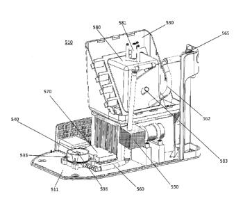
With reference to Figure 14 and according to a fifth embodiment of the present
invention, the fluid dispenser 510 is shown, with the housing 515 having a
depression
512 in order to properly allow for a bottle (not shown) having a handle to be
placed
securely onto the receiving means 535.
14
CA 02901688 2015-08-27
With reference to Figures 15, 16 and 17, the fluid dispenser 510 is shown
without
a housing (not shown) for substantially encasing the fluid dispenser 510, a
receiving
means 535 connected to the housing (not shown) for receiving and positioning a
water
bottle within the fluid dispenser 510, a pump 550 connected to the receiving
means 535
to transfer water out of the water bottle, a water tank 580 and heat sink 595
connected to
the pump 550 for storing and cooling the water, a spout 565 connected to the
water tank
580 to dispense water from the fluid dispenser 510. The receiving means 535 is
positioned on a base 511 of the fluid dispenser 510 and located adjacent to
the water tank
580 and therefore allows the bottle to sit on the same horizontal plane as the
water tank
580, which reduces the space taken in one's kitchen for the fluid dispenser
510. In
operation, the bottle is placed upside down into the receiving means 535,
where said
bottle is pierced by a piercing member 598 as described above. As the spout
565 is
electrically connected to the pump 550, once said spout 565 is pressed, the
pump 550 is
activated and pumps water from the water bottle into the water tank 580
through a first
water delivery tube 560. A worker skilled in the relevant art would appreciate
that the
first water delivery tube 560 could be absent such that the pump 550 would be
connected
directly to the receiving means 535 without departing from the scope of the
invention. If
the water tank 580 is empty, water begins to fill the water tank 580 and will
not yet be
expelled from the spout 565 as the air will escape from a passage 581 located
at the top of
the water tank 580, said passage 581 at a lower height than that of the spout
565. A float
valve 582 is positioned on the inside upper portion of the water tank 580, and
serves to
block the escape of air through the passage 581 as the water level within the
water tank
580 increases. Indeed, as the spout 565 is still activated and thus the pump
550 pumps
water into the water tank 580, the water eventually reaches the level of the
float valve
582. At that point, a float (not shown) within the float valve is pushed
upwardly, blocking
the escape of air through the passage 581. At this point, water will be forced
to be
expelled out of the spout 565 as the only means of escape. During non-use,
water within
the water tank 580 is stagnant and therefore the heat sink 595 located on
lower inside
portion of the water tank 580 will cool the water, with the water located at
the lower end
of the water tank 580 being the coldest. Water will flow from a lower end of
the water
tank 580 through a second water delivery tube 562 in order to deliver the
coldest water to
CA 02901688 2015-08-27
the spout 565. Once the bottle is empty, a new bottle is placed onto the
receiving means
535 and the process resumes. A fan 554 is positioned on the fluid dispenser
510 in order
to expel any heat generated from the heat sink. An electronic circuitry box
570 is also
positioned on the base 511 of the fluid dispenser 510 and in front of the main
heat sink to
improve electronics cooling and to house the circuitry required for the pump,
or for other
equipment such as a thermocouple, etc. Said thermocouple (not shown) would be
attached to a protrusion 583 of the water tank 580. While the spout 565 is not
described
in great detail, a worker skilled in the art would appreciate that pressing
the spout 565
will firstly mechanically activate a check valve located within the spout 565
to allow
water to be expelled from the spout, and secondly electrically activate a
switch which will
in turn activate the pump 550 which will force water out of the bottle and
through the
spout 565. This sequence of activation clears the passage to allow for the
water to be able
to flow through the spout 565 first before the pump is activated second. The
receiving
means 535 of the fluid dispenser 510 is similar to the functioning in the
other
embodiments. Namely, the receiving means 535 is comprised of a piercing member
598
which can pierce the top of a bottle, and connected to a first water delivery
tube 560 or a
pump 550 directly to funnel the water into the water tank 580. A first check
valve tube
540 is also present connected to a first check valve (not shown), which will
also
separately pierce the bottle and allow air to enter said bottle without
spilling any water
and therefore for water to exit the bottle through the piercing member 598.
With reference to Figure 18 and according to another embodiment of the present
invention, the water tank 580 and water tank housing 530 are shown as an
Exploded
view. The area defined in between the water tank 580 and the water tank
housing 530
allows for an insulation foam (not shown) to be inserted therein and keep the
water tank
580 as cold as possible. The water tank 580 is comprised of flanges 584 which
are glued
one to the other for enclosing the water tank 580. The water tank 580 is
further comprised
of fins 586 for securing into grooves 587 of the water tank housing 530. These
fins and
586 and grooves 587 also prevents the insulation foam (not shown) to cause any
unwanted wall deflection when said foam (not shown) expands. Further, both the
water
tank 580 and the water tank housing 530 are shaped so as to only create a two-
part mold
thus making the molding process easier and cheaper.
16
CA 02901688 2015-08-27
Although the device has been described above by reference to certain
embodiments of the device, the device is not limited to the embodiments
described above.
Modifications and variations of the embodiments described above will occur to
those
skilled in the art in light of the above teachings. Moreover, with respect to
the above
description, it is to be repulsed that the optimum dimensional relationships
for the
component members of the present device may include variations in size,
material, shape,
form, funding and manner of operation.
17