Note: Descriptions are shown in the official language in which they were submitted.
CA 02901836 2015-08-26
1
Generic channel filter
Field of the invention
The present invention relates to a channel filter for a communication
apparatus or
for a data transmission link, in particular for a satellite transmission link,
in
particular for a satellite radio transmission link. The satellite radio
transmission link
may be, for example, a Ka band transmission link in a frequency range from
17.7 -
21.2 GHz for the downlink and 27.5 - 31 GHz for the uplink, or may be a Ku or
X
band implementation in a range of 11 or 7 GHz.
Background of the invention
Resonators in the form of a passive component can be used as a channel filter
in
radio transmission links. Channel filters used in practice usually consist of
a
plurality of coupled resonators. With increasing frequency of the signal
transmission on a radio link, the requirements on the filter change, in
particular the
structural and spatial requirements on the one hand as well as the demands on
the usable bandwidth of a filter. The usable bandwidth here is that frequency
bandwidth at which a filter response around a central frequency is constant or
nearly constant.
Depending on the resonant frequency of a filter, it is usually necessary to
adjust,
for example, the geometrical dimensions of a filter.
Channel filters may be used, for example, in so-called output multiplexers. A
typical output multiplexer comprises channel filters, which are connected to a
waveguide busbar. One object of the output multiplexer is to combine
narrowband
high power communication signals on a common waveguide (the so-called
busbar). The channel filters and busbar are coordinated in a complex
development
process. The individual parts for the channel filters as well as the busbar
and any
CA 02901836 2015-08-26
2
necessary additional parts can usually only be ordered and manufactured after
the
end of this development process.
In the currently commonly used Invar circular waveguide technology, as well as
all
other available technologies, various complex construction and development
processes are to be observed, as these devices may comprise many customized
individual parts. The individual parts must usually be individually
manufactured
and procured for each channel filter. By means of the adjusting screws which
are
provided in this technology, a fine adjustment of the resonant frequency in
the
range of a few parts per thousand of the resonant frequency can occur.
However,
a free setting of the filter frequency (resonant frequency) is not possible.
With the TE01n mode, which is frequently used for the temperature compensation
of aluminum filters, it is possible in contrast to displace a complete end
wall of the
resonator, as these modes do not require wall currents from side walls to the
end
wall. This structure is usually used for the compensation of temperature
influences.
Summary of the invention
It can be regarded as an object of the invention to provide a channel filter,
the
resonant frequency of which is adjustable in a wide frequency band.
This object is achieved by the subject of the independent claim. Further
exemplary
embodiments of the invention arise from the dependent claims as well as the
following description.
According to a first aspect of the invention, a channel filter for a
communication
apparatus is provided. The channel filter comprises a first resonator, a
coupling
element having a first longitudinal section and a second longitudinal section,
and a
first adjusting element. The coupling element is designed to couple the first
resonator at least indirectly with an input or output of the channel filter,
wherein the
CA 02901836 2015-08-26
3
first longitudinal section has a greater width than the second longitudinal
section,
and wherein the first adjusting element is disposed at least partially in the
first
longitudinal section and at least partially in the second longitudinal
section.
The amount of energy coupled by means of the coupling element is relevant in
particular for filter characteristics such as bandwidth and alignment.
Therefore, it
may be beneficial if this can be set over the widest possible frequency range.
The first adjusting element is used for adjusting the coupling element. This
may
substantially replace in one embodiment an upper part of the coupling element
and can thus represent in particular a variably configurable coupling element.
The
upper part of the coupling element can either be replaced entirely by the
adjusting
element or be partially present or present in a reduced form. In one
embodiment,
the adjusting element can be designed as a metallic or dielectric screw,
wherein
the metallic screw reduces the amount of coupled energy and the dielectric
screw
increases this.
The first adjusting element extends in a longitudinal direction of the
coupling
element at least partially in the first longitudinal section and the second
longitudinal section. In other words, the first adjusting element is disposed
at the
transition between the first longitudinal section and the second longitudinal
section.
The first adjusting element enables a movement transverse to the longitudinal
direction of the channel filter, i.e. toward and away from the center point of
the
coupling element.
According to one embodiment of the invention, the first longitudinal section
is a
coupling iris.
The coupling iris is designed to couple the first resonator to an adjacent or
immediately adjacent resonator. An adjusting movement of the first adjusting
CA 02901836 2015-08-26
4
element extends transversely to the coupling direction of the coupling iris
between
the first resonator and the adjacent resonator, wherein the coupling direction
usually runs in the direction of the longitudinal direction of the channel
filter.
According to a further embodiment of the invention, the second longitudinal
section is a waveguide.
The cross section of the waveguide is larger than the cross section of the
coupling
iris. As a measure may also be used the size of the coupling iris as well as
the
waveguide in a direction orthogonal to the longitudinal direction of the
channel
filter. The size of the waveguide is greater than the size of the coupling
iris.
According to a further embodiment of the invention, the first adjusting
element is
designed and disposed such that it protrudes in a direction transverse to a
longitudinal direction of the coupling element over a side surface of the
first
longitudinal section.
This may mean that the geometric dimensions of the first adjusting element,
such
as the diameter or at least one edge length, are greater than the width of the
first
longitudinal section. The first adjusting element may be disposed such that it
protrudes over a single or over two side surfaces, in particular over two
opposite
side surfaces of the first longitudinal section.
The first adjusting element may be disposed centrally or eccentrically
(eccentric)
with respect to the first longitudinal section. If the first adjusting element
is
disposed eccentrically, it may in particular protrude only over a single side
surface
of the first longitudinal section. In the case of an eccentric disposition of
the first
adjusting element, this may protrude over a side surface, even if its diameter
or its
edge length is smaller than the width of the first longitudinal section.
The first adjusting element may be an adjusting screw, which is substantially
cylindrically designed. In the case of a central disposition of the adjusting
screw
CA 02901836 2015-08-26
with respect to the first longitudinal section, the diameter of the adjusting
element
is greater than the width of the first longitudinal section.
According to a further embodiment of the invention, the first adjusting
element is
5 disposed in a first longitudinal section, such that it extends in a
longitudinal
direction into the second longitudinal section, between two opposite side
surfaces
of the second longitudinal section.
In other words, this means that the entire adjusting element is not disposed
between two side surfaces of the second longitudinal section, but rather only
that
part of the adjusting element which is located in the longitudinal direction
of the
coupling element in the second longitudinal section.
In the case that the first adjusting element is an adjusting screw, the
diameter is
smaller than the width of the second longitudinal section, and the adjusting
screw
does not protrude over any side surfaces of the second longitudinal section.
According to a further embodiment of the invention, a coupling angle of the
coupling element with the first resonator has a deviation of 00 with respect
to the
first longitudinal direction of the channel filter.
The coupling with an angle deviating by 00 can also help to ensure that a
desired
coupling value is reached and can thus contribute to the adjustment of the
coupling element and the alignment of the operating frequency of the channel
filter.
In particular, the coupling angle between the longitudinal direction of the
coupling
element and the longitudinal direction of the channel filter may be between 1
and
900, more preferably between 1 and 450 (respectively in the geometrically
positive
or negative sense, that is, counterclockwise or clockwise).
CA 02901836 2015-08-26
6
According to a further embodiment of the invention, the channel filter has a
second
resonator, which is coupled with the first resonator via the coupling element.
The channel filter may comprise a plurality of resonators which are
respectively
coupled to one another via a coupling element.
According to a further embodiment of the invention, a coupling angle of the
coupling element with the second resonator deviates with respect to the
longitudinal direction of the channel filter from the coupling angle of the
coupling
element with the first resonator with respect to the longitudinal direction of
the
channel filter.
In one embodiment, the coupling angle of a coupling element between a first
resonator and a second resonator differs from the coupling angles of a
coupling
element between the second resonator and a third resonator.
According to a further embodiment of the invention, the first resonator has a
second adjusting element, which is designed for a coarse adjustment of the
resonant frequency of the first resonator.
Coarse adjustment means here that the operating frequency can be changed in a
frequency range of up to +1- 40%, in particular +1- 10% to 20% of its current
value.
It can in particularly be made possible by the second adjusting element that a
channel filter may be used for different operating frequencies without
necessitating
a new development of a channel filter.
The second adjusting element is here disposed such that it protrudes into an
interior space of the resonator and can be moved in this interior space such
that its
disposition in the interior space can be altered.
CA 02901836 2015-08-26
7
According to a further embodiment of the invention, the first resonator has a
third
adjusting element, which is designed for a fine adjustment of the resonant
frequency of the first resonator.
Through the interaction of the second and third adjusting elements, both a
complete change of the operating frequency (coarse adjustment) as well as an
alignment, for example to manufacturing tolerances (fine adjustment), may
occur.
According to a further embodiment of the invention, the third adjusting
element is
mechanically coupled to the second adjusting element.
Thus, when the second adjusting element is moved, the third adjusting element
is
carried along, so that by means of the third adjusting element occurs a fine
adjustment based on the coarse adjustment prescribed by the second adjusting
element.
According to a further embodiment of the invention, the third adjusting
element is
movable with respect to the second adjusting element.
In other words, an adjusting movement of the third adjusting element is made
relative to the second adjusting element.
According to a further embodiment of the invention, the channel filter has a
shorting element, which is disposed to bridge at least the second resonator.
The shorting element may also be designated as a bridging element, which
bridges one or more adjacent resonators.
In summary, the channel filter according to one embodiment of the invention
can
be described as follows.
CA 02901836 2015-08-26
8
The channel filter, for example an output multiplexer, can be designed such
that
the following conditions are met: a generic channel filter is independent of
the
project-based development and design process; the primary filter parts are
identical across projects and can be pre-purchased and kept in stock; faster
assembly of the individual parts is possible; an output multiplexer assembled
with
the use of such a generic channel filter can be set through adjustment of the
entire
waveguide band.
One aspect of the channel filter is to realize by means of a TE01n
implementation
a channel filter for an output multiplexer which is as widely adjustable in
frequency
and bandwidth as possible. The adjustability of the frequency is limited
ideally only
by the failure-mode-free region of the useful mode, which in the Ka band is
approximately 1 GHz. To cover a larger frequency range, however, the
geometrical dimensions such as the diameter of the resonators can be easily
adjusted. The implementation is independent of the frequency band, a Ka band
implementation at 20 GHz/30 GHz is as possible as a Ku or X band
implementation in the region of 11, or 7 GHz.
The properties of the resonance mode are used to preset the frequency by means
of a coarse adjusting plate. Fine adjustment may take place using a fine
adjusting
screw integrated in the coarse adjusting plate.
The adjustment of the coupling can occur, for example, by means of iris
adjusting
screws. These screws can be significantly larger than the actual iris is long
or
wide. With such iris adjusting screws, the cross section of the iris can be
effectively reduced. The overlapping region with the waveguide (i.e. the area
in
which the screw protrudes over the iris) can be dimensioned such that it is
operated at the filter frequency above its so-called cut-off frequency. The
cut-off
frequency is that frequency above which an electromagnetic wave energy is
transported, and below which can be detected only an electromagnetic field.
CA 02901836 2015-08-26
9
The resonators may particularly be disposed such that the lateral distance of
the
filter from the busbar can be kept constant for different operating
frequencies and
in addition, the total length does not exceed a predetermined length. This is
partly
due to the fact that the maximum total length of the multiplexer is typically
limited
by the spatial requirements in the usage environment of the channel filter. An
increased distance between the channels may therefore reduce the possible
number of channels. On the other hand, the degradation of filter performance
can
increase with increasing distance of the channels from the bus bar,
particularly
with respect to temperature.
The resonators are in particular disposed in a row. A desired channel spacing
can
thereby be realized on the busbar. Electrically, this structure of the channel
filter
corresponds to a so-called extracted pole structure, that is, a filter with
transmission zero points can be realized. A connecting waveguide between the
poles can be conducted above or below the two pole resonators. It can either
be
conducted centrally or slightly laterally offset with respect to a
longitudinal axis or
central axis of the channel filter, in order to facilitate the accessibility
of the
adjusting screws and plates.
The coupling irises may either be disposed in a direct line or directed at any
desired angle from the resonator, for example for targeted suppression of
interference modes. In particular the coupling iris between the first and
second
resonator of the busbar may be longer than the rest of the coupling irises in
one
embodiment, so that the couplings can be realized in an arc. As a result, the
electrically necessary coupling value may no longer be achieved. To solve this
problem, a section of waveguide with a widened cross section may be introduced
between the short coupling and decoupling irises. The waveguide corresponds
here to the second longitudinal section of the coupling element. In
particular, the
depth of the iris may be of significance, as it may depend on the depth of the
iris
whether the iris acts evanescently (damping), or allows the propagation of an
electromagnetic wave.
CA 02901836 2015-08-26
Optional variable shorts, which can be realized by means of shorting plates,
can
be introduced on the connecting waveguide between the extracted poles. The
connecting waveguide can be made, for example, from half-shells which are
screwed together or from aluminum sections. Optionally, the waveguide can be
5 outfitted on one or both sides with a replaceable shorting plate to
increase the
adjustment range. Further adjusting elements in the form of adjusting screws
can
additionally be placed in the connecting waveguide.
The pole resonators may either be disposed at the filter input or at any
desired
10 location in the filter. The filter order can be easily expanded by
adding more
resonators at the input or output. The addition of further pole resonators is
also
possible.
For a reduction of the temperature dependence, the filter can either be made
from
temperature-stable materials, such as Inver, or from temperature-instable
materials, such as aluminum, wherein it is outfitted with a temperature
compensation unit.
The properties of the channel filter can be described as follows.
The channel filter enables use at differing operating frequencies, which can
deviate strongly from one another, at constant mechanical dimensions such as
length and width. This is a generic channel filter, so that a new development
for
different operating frequencies and areas of application can be avoided.
During
development, it may be necessary only to supply the adjustment data. Identical
parts sets for the generic channel filter can be obtained in large quantities,
since
an individual design of the components depending on the operating frequency is
not required. A significant reduction in the development time can take place
through a reduction of development effort and elimination of project-related
design
and manufacturing time. Cost savings can be enabled through mass production,
elimination of design costs and partial elimination of development costs. The
channel filter enables an individual adjustment with a large adjustment range,
so
CA 02901836 2015-08-26
11
that an achievable production accuracy of generic parts is sufficient and the
individual parts need not be made in view of the future operating frequency.
By
producing large numbers of like parts, the possibility arises for automation
of the
adjustment. A high degree of planning security can result from standard
processes
and parts. With respect to consideration of thermal and mechanical parameters
during the development of a channel filter, generic analysis with worst-case
values
is possible. Irrespective of the target frequency and the bandwidth of a
channel
filter, identical components may be used due to the different adjusting
possibilities.
The center frequency of the filter is substantially determined by the resonant
frequency of the filter resonators. As described above, a second adjusting
element
in the form of an adjusting plate can be used for coarse adjustment of the
resonant
frequency. Such an adjusting plate enables setting of the frequency in very
broad
ranges. A third adjusting element in the form of a screw which has a smaller
cross
section or diameter than the adjusting plate and may be disposed in the axis
of the
plate, further enables the fine adjustment of the filter. The third adjusting
element
may comprise metallic or dielectric material.
Brief description of the drawings
Hereinafter will be more nearly discussed with reference to the accompanying
drawings exemplary embodiments of the invention. The representations are
schematic and not to scale. Like reference characters refer to identical or
similar
elements.
Figure 1 shows a schematic representation of a channel filter according
to
one embodiment of the invention.
Figure 2 shows a schematic representation of a resonator of a channel
filter
according to a further embodiment of the invention.
CA 02901836 2015-08-26
12
Figure 3 shows a schematic representation of a channel filter according
to a
further embodiment of the invention.
Figure 4 shows a schematic representation of a channel filter according
to a
further embodiment of the invention.
Figure 5 shows a schematic representation of a channel filter according
to a
further embodiment of the invention.
Figure 6 shows a schematic representation of a channel filter according to
a
further embodiment of the invention.
Figure 7 shows a schematic representation of a channel filter according
to a
further embodiment of the invention.
Figure 8 shows a schematic representation of a channel filter according
to a
further embodiment of the invention.
Figure 9 shows a schematic representation of a channel filter according
to a
further embodiment of the invention.
Detailed description of exemplary embodiments
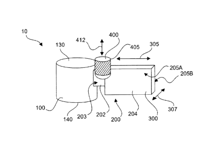
Fig. 1 shows a part of a channel filter 10 having a resonator 100 and a
coupling
element 200 coupled thereto.
The resonator is designed as a cylindrical cavity with two opposing base or
end
surfaces 130, 140. The coupling element 200 is coupled to a circumferential
surface of the cylindrical cavity.
The coupling element 200 has a first longitudinal section 202 and a second
longitudinal section 204. A first adjusting element 400 is disposed such that
it
CA 02901836 2015-08-26
13
extends in a direction transverse to the longitudinal direction 305 of the
coupling
element 200 in both the first longitudinal section 202 and the second
longitudinal
section 204, and that it enables an adjusting movement in the direction of the
arrow 412.
The first longitudinal section has a side surface 203. The cross section or
the base
surface 405 of the adjusting screw 400 is designed such or the adjusting screw
400 disposed such that the adjusting screw protrudes over the side surface 203
(out of the drawing plane toward the viewer, in the direction of arrow 307,
which
indicates the width of the first coupling element). In one embodiment, the
adjusting
screw may also protrude over the side surface of the first longitudinal
section 202
in the rear in fig. 1.
The second longitudinal section 204 is wider in direction 307 than the first
longitudinal section 202. The adjusting screw 400 is designed and disposed
such
that it is located in the region of the second longitudinal section 204
between the
side surfaces 205A, 205B.
The dimensions of the channel filter are frequency dependent. For a channel
filter
in the Ku band, the first longitudinal section 202 may have a width of a few
cm, for
example between 3 and 5 cm, and the second longitudinal section 204 can have a
width of over 5 cm, for example between 5 and 12 cm, in particular
approximately
9.5 cm. The diameter of the adjusting screw 400 may be greater in one
embodiment than the width of the first longitudinal section 202 and smaller
than
the width of the second longitudinal section 204.
Fig. 2 shows a resonator 100 having a second adjusting element 110 comprising
an adjusting plate 114 and a shaft 116 designed with both a third adjusting
element 120 and an adjusting screw, which is disposed in the shaft 116 and can
be moved relative to the second adjusting element 110 through a rotational
movement of the adjusting screw 120. The second adjusting element 110 can also
CA 02901836 2015-08-26
14
execute the adjusting movement by means of a rotational movement of the shaft
116 with respect to the base surface 130 of the resonator.
Both the second adjusting element and the third adjusting element enable an
adjusting movement in a direction along the arrow 112, 122.
The adjusting plate 114 can be designed to execute an adjusting movement of
several cm, for example between 1 cm and 4 cm. The adjusting screw 120 can be
designed to execute an adjusting movement of a few tenths of a mm up to a few
mm, for example between 0.1 mm up to 2 mm. The adjusting screw 120 has a
smaller cross section than the adjusting plate 114 and the shaft 116.
Fig. 3 shows a side view (above) and plan view (below) of a channel filter 10
with
four resonators 100, wherein directly adjacent resonators are respectively
coupled
together via a coupling element. The channel filter 10 further comprises a
connecting element 500.
The width 16 and length 18 of the channel filter can be held constant or
substantially constant independent of the operating frequency, meaning that no
adjustments of the geometric dimensions of the channel filter depending on a
desired operating frequency are necessary.
Fig. 4 shows a channel filter 10 having a filter input 12 and a filter output
14. The
longitudinal direction of the channel filter is indicated by a dotted line. A
connecting
element 500 connects two resonators.
Fig. 5 shows a channel filter 10 in a view of the resonator assembly from
above. A
waveguide 600 is disposed between the poles and can be laterally displaced
with
respect to a longitudinal axis of the channel filter 10 for better access to
the
adjusting elements 110, 120. The waveguide can alternatively be disposed
centrally.
CA 02901836 2015-08-26
Fig. 6 shows a channel filter 10 with coupling elements 200, which are coupled
with the resonators 100 at various angles 210 with respect to the longitudinal
direction of the channel filter. The connecting waveguide 600 is disposed
centrally,
and can also be laterally displaced for better accessibility of the adjusting
5 elements, as has been shown in fig. 5.
Fig. 7 shows a channel filter 10 with coupling coupling elements 200, which
are
coupled with the resonators 100 at various angles 210 with respect to the
10 longitudinal direction of the channel filter and a laterally displaced
connecting
waveguide 600. The coupling at different angles is executed as a waveguide
structure with enlarged cross section 300 in the central region, in order to
achieve
a desired coupling value. Sections 200 and 300 represent the first
longitudinal
section and the second longitudinal section of the coupling element between
two
15 resonators.
Fig. 8 shows a channel filter 10, wherein the connecting waveguide 600 is
displaced in the longitudinal direction with respect to the embodiment in fig.
7,
meaning that it bridges other resonators.
Fig. 9 shows a channel filter 10 and indicates expansion possibilities for a
higher-
circuit filter (any number of resonators may be added, these are shown as
dotted
lines).
CA 02901836 2015-08-26
16
List of reference characters
channel filter
12 input
5 14 output
16 width
18 length
100 resonator
110 second adjusting element
10 112 adjusting movement
114 plate
116 shaft
120 third adjusting element
122 adjusting movement
130 first surface
140 second surface
200 coupling iris
202 first longitudinal section
203, 205 side surface
204 second longitudinal section
210 coupling angle
300 waveguide
305 longitudinal direction
307 width
400 first adjusting element
405 base surface
412 adjusting movement
500 connecting element
600 shorting element