Note: Descriptions are shown in the official language in which they were submitted.
CA 02902109 2015-08-21
WO 2014/132049 PCT/GB2014/050559
1
APPARATUS FOR THE GENERATION OF LOW-ENERGY X-RAYS
Field of the Invention
The present invention relates to apparatus for the generation of X-rays. It is
particularly applicable, but by no means limited, to low-energy X-ray
generators for
sterilising medical articles, pharmaceutical products, or packaging for food
or drink
products. Other possible applications are discussed below.
Background to the Invention
X-ray generators are often used in manufacturing or packaging facilities to
sterilise
medical articles, pharmaceutical products, or packaging for food or drink
products.
In such applications, such as the sterilisation of packaging, conventionally
the
article to be sterilised is exposed to X-ray radiation produced by means of a
radioactive source such as radioactive cobalt. Such radiation comprises "hard"
X-
rays, i.e. radiation having a high energy, measured in millions of electron
volts
(eV).
"Hard" X-rays are typically produced by a radioactive decay process, when
nuclei
undergo a transition into a different element of the periodic table,
simultaneously
emitting energy through electromagnetic waves. This happens in so-called
"Gamma-factories", which utilize the decay of radioactive cobalt and emit high-
energy X-ray photons (in this particular case called gamma-particles, although
this
is still X-ray radiation, just having a specific energy or wavelength).
Current sterilisation standards require a dosage of the order of 25 kGy
(kilograys)
to achieve efficient destruction of bacteria to an acceptable level. Such a
dosage
requires exposure of the packaging to a radioactive source for a prolonged
period
of time, usually several hours. For this to be practicable, such sterilisation
is
generally carried out in batches comprised of one or more pallet-loads of
products.
This is possible because the "hard" X-rays, by virtue of their high energy,
have the
ability to penetrate deep into a large stack of packages.
CA 02902109 2015-08-21
WO 2014/132049 PCT/GB2014/050559
2
However, more recently, as discussed in GB 2444310 A, it has been found that
low energy or "soft" X-rays can be better suited to the sterilisation of
surfaces.
"Soft" X-rays are characterised by being of relatively low energy, with
quantum
energies predominantly in the range of 5 to 20 keV. Because of their low
energy,
these soft X-rays have higher absorption. As a result, the efficiency of the X-
rays
in destroying bacteria on the surface is high and the total exposure that is
required
may be lower that when using high energy X-rays. The lower X-ray dosage is
also
desirable in that it reduces the risk of damaging the material being
sterilised, and
the softness of the X-rays also allows them to be used safely in a production
line
without risk to personnel or the need for extensive lead shielding.
Such "soft" X-rays can be generated using a particle accelerator (for example,
an
electron gun) to generate a flow of charged particles. When these particles
are
decelerated due to the interaction with matter ¨ for example, when they hit a
metal
target ¨ they emit electromagnetic radiation. If the initial energy of the
particle
beam is sufficiently high, the electromagnetic radiation is located in the X-
ray
range of the emission spectrum.
Electrons also emit X-rays when they change the direction of their motion, as
in
the case of synchrotrons (synchrotron radiation can be generated in a broad
spectral range, including X-rays).
In the present work, we deal with the acceleration-based approach to soft X-
ray
production. The majority of X-ray sources operate at low-power levels (as
these
are medical/dental X-ray apparatuses, non-destructive testing (NDT) and
luggage
screening equipment). This is determined by the specific tasks of the
equipment:
they have to produce an X-ray beam which will assure the best possible image
quality. Also, these sources are typically generated as a point-like source,
due to
the requirements of X-ray imaging. The best way to create such beams for
imaging applications is to accelerate electrons in a vacuum and then to direct
them
onto a metal target.
CA 02902109 2015-08-21
WO 2014/132049 PCT/GB2014/050559
3
However, vacuum-based X-ray tubes with heated cathodes are not well suited for
long periods of heavy duty operation, as would be the case with sterilisation
applications. Therefore, in the present work, we have chosen an approach to X-
ray production based on the generation of electrons in gas-filled devices with
cold
cathodes, rather than in vacuum-based electron beam sources with heated
filaments.
Existing "soft" X-ray generator systems, such as the one disclosed in
GB 2444310 A, suffer from a number of disadvantages, at least in part
resulting
from the arrangement of the cathode and anode electrodes and the occurrence of
arcing between them. Arcing between the electrodes, and the consequent erosion
of the electrodes, leads to a decrease in the operational lifetime of the
system. It
also affects its ability to produce stable, reliable and reproducible X-rays
homogeneously over a large cross-section of the emitter head, and to provide
continuous and consistent operation.
Embodiments of the present invention therefore seek to achieve one or more of
the following: (1) to increase the operational lifetime of the X-ray generator
system;
(2) to enable it to operate over a large cross-section of the X-ray emitter
head; (3)
to improve stability and reproducibility (minimizing pulse to pulse variation
of
energy generated) of the device; and (4) to avoid arcing and discharge
instabilities
which reduce the reliability of the device when used in industrial settings
requiring
high levels of continuous and consistent operation.
Summary of the Invention
According to a first aspect of the present invention there is provided an X-
ray
source as defined in Claim 1 of the appended claims. Thus, there is provided
an
X-ray source for producing soft X-rays, the X-ray source comprising: a cathode
having an electron-emitting structure supported by a support structure, the
electron-emitting structure being at least partially transparent to X-rays
within a
region bounded by the support structure; an anode having an X-ray emitting
surface parallel to the electron-emitting structure of the cathode; and an
electrically
insulating spacer arranged between the anode and the cathode; wherein the
CA 02902109 2015-08-21
WO 2014/132049 PCT/GB2014/050559
4
electron-emitting structure of the cathode and the X-ray emitting surface of
the
anode are arranged such that, in use, the electron-emitting structure is
operable to
bombard the anode with electrons, causing X-rays to be emitted from the X-ray
emitting surface and to pass through the cathode; and wherein the insulating
spacer is arranged between the anode and the support structure of the cathode
and projects beyond the support structure, across part of the anode, into the
said
region.
The expression "region bounded by the support structure" as used above and
herein should be interpreted broadly, to encompass an arrangement in which the
support structure is present on only two opposing sides of the region in
question,
as well as arrangements in which the support structure substantially or
completely
surrounds the region in question.
By virtue of the insulating spacer projecting beyond the cathode support
structure,
into the said region, across part of the anode, this avoids or at least
mitigates the
formation of places in the vicinity of the cathode and anode where the
electric field
strength could otherwise rise substantially.
In effect, the insulating spacer
"smoothes" the electric field distribution in the vicinity of the anode and
cathode.
This reduces the probability of electric breakdown between the cathode and
anode
electrodes, thereby reducing the likelihood of arcing between the electrodes,
and
reducing the occurrence of erosion of the electrodes. As a consequence, this
increases the operational lifetime of the X-ray generator system, makes it
more
usable for continuous and consistent operation at elevated power levels,
enables it
to deliver a more homogeneous discharge over a large cross-section of the X-
ray
emitter head, and improves the overall stability, reliability and
reproducibility of the
device.
In a presently-preferred embodiment the distance of projection of the
insulating
spacer beyond the cathode support structure, into the said region, is about 15
mm.
This has been found to give optimum results.
CA 02902109 2015-08-21
WO 2014/132049 PCT/GB2014/050559
Preferably the width of the X-ray emitting surface not covered by the
insulating
spacer is in the range of about 3 cm to about 10 cm.
Preferably the thickness of the insulating spacer is about 2 mm.
5
Preferably the insulating spacer is made of a ceramic material such as alumina
(A1203). However, other insulating materials (in particular, other ceramics)
may be
used instead.
Preferably the electron-emitting structure of the cathode has a grid or mesh
structure. Particularly preferably the geometric transparency of the grid or
mesh
structure is about 70% to 80%.
Preferably the X-ray source further comprises an X-ray transparent window on
the
opposite side of the cathode from the anode, the window defining a chamber
between the window and the anode. In the presently-preferred embodiment this
chamber contains a gas at sub-atmospheric pressure. The gas may be an inert
gas such as helium or nitrogen, or may be air. Preferably a molecular sieve is
provided between the gas supply and the chamber, to prevent moisture or dust
etc. from entering the chamber. A vacuum pump may also be provided in
communication with the chamber, to achieve and maintain sub-atmospheric
pressure within the chamber.
Preferably the X-ray transparent window comprises Kapton TM (RTM), as this has
been found to have advantageous properties (including becoming stronger when
exposed to X-rays, whereas other materials can break down or become brittle
over
time).
Particularly preferably the window is formed of an electrically conductive
material,
or further comprises a coating formed of an electrically conductive material.
This
enables the window to be held at the same electric potential as the electron-
emitting structure of the cathode, thereby preventing charged particles from
the
cathode being accelerated towards the window and damaging it. Accordingly, the
CA 02902109 2015-08-21
WO 2014/132049 PCT/GB2014/050559
6
window may advantageously be electrically connected to the electron-emitting
structure of the cathode.
Preferably the anode is formed of a metal block, at least several millimetres
in
thickness.
Preferably the anode further comprises cooling means, such as one or more
cooling pipes in thermal communication with the anode.
Preferably the electron-emitting structure of the cathode is at least partly
formed of
copper. Preferably the anode is also at least partly formed of copper. For
example, it may be formed of bulk copper, or iron coated with copper. Although
copper is our presently-preferred material for the cathode and anode, other
materials may be used instead, provided they have characteristic emission
lines in
the spectral range below 10-12 keV.
The X-ray source may further comprise a power supply cable electrically
connected to the anode.
Preferably the X-ray source further comprises isolation material configured to
match the wave impedance of the power supply cable with the wave impedance of
the anode. This advantageously reduces reflections of the voltage pulses
applied
to the emitter head.
Preferably the electron-emitting structure of the cathode is at ground
potential.
Preferably the electron-emitting structure of the cathode is electrically
connected
to the cathode support structure, enabling the electron-emitting structure and
the
cathode support structure to be held at a common potential.
Preferably the cathode support structure is connected to, or integrally formed
with,
a housing structure for the X-ray source. The housing structure may be
arranged
around at least part of the anode.
CA 02902109 2015-08-21
WO 2014/132049 PCT/GB2014/050559
7
Preferably the insulating spacer extends between the housing structure and the
anode.
Preferably the X-ray source further comprises means for generating a voltage
between the anode and the cathode.
Particularly preferably the means for generating a voltage comprises inductive
energy storage means. With such an arrangement, rising current results in a
voltage rise on the inductors, thus effectively reducing the voltage applied
to any
spark that may be created within the X-ray generator ¨ effectively functioning
as a
self-damping limiter. This further improves the operational stability and
longevity
of the X-ray device.
Preferably the means for generating a voltage is configured to supply high-
voltage
short-duration pulses to the anode.
Preferably the X-ray source is configured to emit X-rays with quantum energies
in
the range of 5 keV to 20 keV, although this energy may be increased if
required by
a particular application.
According to a second aspect of the invention there is provided sterilisation
apparatus comprising an X-ray source in accordance with the first aspect of
the
invention.
According to a third aspect of the invention there is provided a production
line or a
manufacturing or packaging facility comprising sterilisation apparatus in
accordance with the second aspect of the invention.
According to a fourth aspect of the invention there is provided a method of
sterilising an article, the method comprising irradiating the article with X-
ray
radiation using an X-ray source in accordance with the first aspect of the
invention.
CA 02902109 2015-08-21
WO 2014/132049 PCT/GB2014/050559
8
The article being irradiated may be, for example, a medical article, a
pharmaceutical product, packaging material for a food or drink product, a
plastic
film, a blood sample, or a foodstuff or beverage.
According to a fifth aspect of the invention there is provided an outcoupling
window for an X-ray source, the window comprising a material that is at least
partially transparent to X-rays; wherein the window is formed of an
electrically
conductive material or further comprises a coating formed of an electrically
conductive material.
Brief Description of the Drawings
Embodiments of the invention will now be described, by way of example only,
and
with reference to the drawings in which:
Figure 1 is a schematic cross-sectional diagram of an X-ray generator
according to
an embodiment of the present invention;
Figure 2 illustrates X-ray transmission data for a KaptonTM window of the X-
ray
generator (the plotted data being X-ray transmission data in respect of Kapton
TM
polyimide film 75 pm thick);
Figure 3 is a plot of mass-energy absorption coefficient versus photon energy
for
typical plastic packaging material (of density 1 g cm-3);
Figure 4 is a plot of dose efficiency as a function of photon energy;
Figure 5 illustrates the generation of X-rays by an electron beam impinging on
a
metal target;
Figures 6a, 6b and 6c provide a comparison of theoretical and experimental
bremsstrahlung spectra;
Figure 7 is a plot showing the intensity of Cu Ka characteristic radiation;
Figure 8 is a schematic diagram of production line apparatus in which a
plastic film
is sterilised with X-rays;
Figure 9 is a plot showing specific dose-rate distribution along a plastic
film; and
Figure 10 illustrates representative data for the dose-area integral for a
copper
anode X-ray source, calculated for different distances and voltages.
CA 02902109 2015-08-21
WO 2014/132049 PCT/GB2014/050559
9
Detailed Description of Preferred Embodiments
The present embodiments represent the best ways known to the applicants of
putting the invention into practice. However, they are not the only ways in
which
this can be achieved.
Overview of presently-preferred embodiment
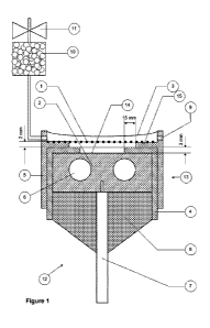
Figure 1 illustrates an X-ray generator 12 comprising a gas-filled flash X-ray
tube
with inductive energy storage for the sterilisation of products such as
plastic
medical articles. The emitter head 13 of the X-ray tube comprises a cold
cathode
1 made of a highly transparent metal grid or mesh, and an anode 2 made of
massive metal energized by high-voltage short-duration pulses. Electrons
emitted
by the grid cathode 1 strike the metal anode 2 and generate characteristic and
bremsstrahlung X-ray radiation from the emission surface 14 of the anode 2.
The
X-ray radiation passes through the cathode grid 1 and irradiates the
article(s) to be
sterilised.
An electrically insulating (preferably ceramic) spacer 4 provides means to
avoid
shorting or arcing of the anode-cathode discharge gap upon application of
pulsed
power, thereby achieving increased operational lifetime and more stable and
reproducible operation, while also creating conditions for generating an X-ray
beam over a large area.
Furthermore, in the presently-preferred embodiment, a power supply based not
on
capacitive energy storage but on inductive energy storage is used.
It should be noted that the diagram in Figure 1 is not to scale. Furthermore,
the
measurements included in this diagram relate only to a presently-preferred
embodiment, and are by way of example only; in alternative embodiments the
constituent features may have different measurements. The component regions
on the left side of Figure 1 predominantly mirror those on the right; for
clarity each
component has been labelled only once.
CA 02902109 2015-08-21
WO 2014/132049 PCT/GB2014/050559
Detailed description of X-ray generator
Figure 1 illustrates an X-ray generator 12 according to a presently-preferred
embodiment of the present invention. A homogeneous X-ray beam is generated
from an irradiator with a large cross-section area, rather than from a point
source.
5 A wide range of shapes and dimensions of the emitter head 13 are
possible. For
example, it may be long and thin (e.g. extending with uniform cross-section
normal
to the plane of Figure 1), round or square, or any other shape ¨ depending
upon
the requirements dictated by the shape of the target being irradiated.
10 As illustrated, the electrode system of the X-ray generator 12 comprises
a cathode
1 and an anode 2. The cathode 1 has a grid or mesh electron-emitting structure
(as described in more detail below; a number of different metals which possess
good heat and electric conductivity may be used). The cathode 1 is shaped and
configured such that X-rays can penetrate the structure relatively freely. In
the
presently-preferred embodiment the mesh of the cathode 1 has a geometric
transparency of about 70% to 80% (below this range it will work less
efficiently,
lowering the energy yield conversion into X-rays, while above this range the
mesh
may become too fragile and break).
The anode 2 is made of a metal block at least several millimetres in
thickness,
which provides the possibility for enhanced cooling of the anode 2 and heat
removal via cooling pipes 6. This is important for stable and continuous
operation
of the device in a real operating environment. The metal block may be cooled
using a wide range of cooling systems employing a heat exchange. For example,
a water based cooling system operating at a rate of 1 litre/second would be
sufficient to dissipate 200 kW of heat energy absorbed by the metal block.
The preferred material for the electrodes 1, 2 is copper, due to the fact that
copper
emits a strong line of characteristic radiation Cu K ¨ the first
characteristical K
emission line of copper in a low-energy (8 keV) part of the X-ray spectrum.
However, it is possible to make the electrodes 1, 2 from other metals or
conductive
materials, of which their surface can be covered with a thin copper layer to
provide
similar emission properties to bulk copper. It is preferable that both cathode
1 and
CA 02902109 2015-08-21
WO 2014/132049 PCT/GB2014/050559
11
anode 2 consist of, or have their surface covered with, similar material in
order to
avoid an eventual change in the emission spectrum properties due to changes of
the surface composition in the case of spattering, which can occur if the
electrodes
1, 2 are composed of different materials. Copper is our presently-preferred
material for the electrodes 1, 2; however, other materials may be used
instead,
provided they have characteristic emission lines in the spectral range below
10-12
keV.
The gap between the cathode 1 and the anode 2 is filled with gas at sub-
atmospheric pressure (low or intermediate pressure). It can be a specially
selected inert gas, such as helium or nitrogen, but alternatively normal air
can be
used to fill in the device. Gas pressure inside the device can be controlled
with an
external vacuum pump connected to the device through an opening 9. To fill in
the gas, an opening from the opposite side of the vessel is used, which
provides a
controlled gas leakage through a valve 11. To ensure that no moisture, dust,
etc.
enters the irradiator, a molecular sieve 10 is placed after the valve.
A working prototype has been successfully demonstrated using a discharge in
air
at a pressure of 5 mbar. However, as mentioned earlier, other gases may be
used, which would allow embodiments to operate at different pressures.
Another important part of the system is an outcoupling window 3, which forms a
chamber between the anode 2 and the window 3 in which the above-mentioned
gas is contained, and also encloses the cathode 1. In the presently-preferred
embodiment this window 3 is made of a polyimide film, preferably KaptonTM.
Although other materials may be used, to date KaptonTM is the best we have
found, as it demonstrates some particularly attractive features in this
application,
as it becomes stronger when exposed to X-rays, while other materials can break
down or become brittle over time. Ideally the window 3 should meet several
requirements: it should withstand the pressure difference and not break, have
low
absorption losses for X-rays (see transmission data in Figure 2), and should
not
lose its strength and transparency under the influence of intense X-ray
irradiation.
Materials other than Kapton TM can be used for the outcoupling window 3,
provided
CA 02902109 2015-08-21
WO 2014/132049 PCT/GB2014/050559
12
they have material properties and transmission characteristics similar to
those of
Kapton TM, or better, although at present we are not aware of any such
material.
The window 3 is preferably formed of an electrically conductive material, or
the
inner surface of the window 3 may be covered with a thin layer of electrically
conductive material. For example, a layer of conductive material such as
graphite
may be deposited on the inner surface of the window 3. In our presently-
preferred
embodiment, however, a commercially available electrically-conductive
polyimide
film, KaptonTM RS, is used to form the window 3. KaptonTM RS comprises a
polyimide film loaded with conductive carbon. By making the window 3
electrically
conductive, this enables the window 3 to be kept at the same electric
potential as
the grid or mesh of the cathode 1, thereby preventing an electric field from
"hanging" between the cells of the cathode grid/mesh in the direction of the
outcoupling window 3 (which would result in a constant flow of accelerated
electrons towards the window 3, resulting in sputtering of the window material
and
causing it to be damaged).
The cathode 1 is mounted on, and electrically connected to, a metal support
structure 15 which is kept at ground potential. Thus the cathode 1 has similar
potential. The cathode support structure 15 is connected to, or integrally
formed
with, a housing structure 5 in which at least part of the anode 2 is mounted.
The
cathode support structure 15 (and the rest of the housing structure 5) is
electrically
isolated from the anode 2 by the insulating spacer 4. The outcoupling window 3
is
also mounted on the housing structure 5, over the cathode 1. If, as in the
presently-preferred embodiment, the outcoupling window 3 is electrically
conductive, then the outcoupling window 3 is electrically connected to the
housing
structure 5 and the cathode support structure 15, so that the window 3 is at
the
same electric potential as the cathode 1.
The cathode support structure 15 and/or the housing structure 5 may be formed
of
stainless steel, or any other suitable material.
CA 02902109 2015-08-21
WO 2014/132049 PCT/GB2014/050559
13
High-voltage pulses are supplied by a power supply to the irradiator via a
high-
voltage cable 7. The power supply is preferably a high-voltage generator with
inductive energy storage. The latter is important for stable device operation,
and
the reasons for this are explained below.
A bulk piece of isolation material 8 matching the wave impedance of the power
cable 7 with the wave impedance of the emitter head 13 serves effectively as a
transformer, that reduces the reflections of the voltage pulses applied to the
emitter head 13.
Insulating (e.g. ceramic) spacer
Although, in the presently-preferred embodiment described below, the
insulating
spacer 4 is made of a ceramic material (e.g. alumina), in alternative
embodiments
it can be made of other insulating materials instead.
The ceramic spacer 4 serves to insulate the anode's emitter surface 14 from
the
cathode support structure 15 and the metal housing 5, and simultaneously
improves the operational stability of the emitter.
In order to achieve this
improvement in stability, we have decreased the size of the emitter surface 14
by
making the opening provided by the ceramic spacer 4 slightly smaller than the
opening provided by the cathode support part of the housing 15. In the example
shown in Figure 1, this difference is 15 mm of additional ceramic material
that
projects across the surface of the anode 2. Regarding this distance by which
the
ceramic spacer 4 projects across the anode 2, distances shorter than 15 mm
were
tested, with unsatisfactory results. Distances larger than 15 mm will result
in
effective operation, but would reduce the area of X-ray emission, and hence
the
yield. Thus, in the presently-preferred embodiment, the distance by which the
ceramic spacer 4 projects across the anode 2 is about 15 mm.
By having this ceramic spacer 4 we avoid the formation of places in the
vicinity of
the cathode and anode electrodes 1, 2 where the electric field strength could
rise
substantially.
In effect, the ceramic spacer 4 "smoothes" the electric field
distribution in the vicinity of the electrodes 1, 2. In X-ray sources known in
the art,
CA 02902109 2015-08-21
WO 2014/132049 PCT/GB2014/050559
14
which have places in which the electric field strength can rise substantially,
there is
a substantial chance that there will be a short electric breakdown between the
electrodes, resulting in arcing of the charge and a disruption of the X-ray
generation. The result would be the erosion of the electrodes and subsequent
deterioration of the inner side of the device.
As illustrated, the insulating ceramic spacer 4 preferably also extends
downwards,
between the housing structure 5 and the sides of the anode 2, as well as
projecting across the surface of the anode 2. Thus the housing structure 5 is
electrically isolated from the anode 2.
The thickness of the ceramic spacer 4 is preferably about 3 mm, as
illustrated.
The ceramic spacer 4 is preferably fitted in contact with the upper surface of
the
anode 2, and in contact with the underside of the cathode support structure 15
and
the inner surface of at least part of the housing 5.
The width of the X-ray emitting surface 14 of the anode 2 exposed between
opposing edges of the ceramic spacer 4 is preferably in the range of about 3
cm to
about 10 cm. The X-ray beam produced from the exposed X-ray emitting surface
14 is homogeneous and well-directed.
As mentioned above, although the spacer 4 of the presently-preferred
embodiment
is made of a ceramic material (e.g. alumina), in alternative embodiments other
insulating materials can be used instead.
Our experience shows that in the case of a regular design of the electrode,
when
there is no protective insulating spacer 4 (not necessarily ceramics), once in
every
10,000 pulses a spark due to discharge instabilities might occur. At power
levels
higher than several kW, more thermally stable materials would be used;
however,
not a material such as Teflon TM, as it is too isolating of the charge. Given
that our
device can operate at a repetition rate of up to 20 kHz, this effectively
would mean
that without these protective means the device might be suited for short-term
scientific research but would be completely unfit for routine industrial
operation.
CA 02902109 2015-08-21
WO 2014/132049 PCT/GB2014/050559
However, the protective insulating spacer 4 enables the present X-ray
generator to
be employed in long-term continuous operation, such as on a production line in
a
manufacturing or packaging facility.
5 Another important feature of our system is a combination of two
protective means.
One is the above-mentioned specially shaped ceramic spacer 4, and the other is
the use of a power supply based not on capacitive energy storage but on
inductive
energy storage. The difference here occurs due to the following effects:
10 In a capacitive storage device if an accidental breakdown occurs, it is
in no way
affected by the power supply itself, and can develop a full-blown electric
spark that
would damage the surface of the electrodes and the device itself. However, by
employing an inductive energy storage power supply, rising current results in
a
voltage rise on the inductors, thus effectively reducing the voltage applied
to a
15 spark. In effect, it functions as a self-damping limiter. Together with
the ceramic
protector 4, this substantially improves the operational stability and
longevity of the
device.
There is also an ancillary but beneficial by-product from the present system,
namely UV radiation generation within the chamber between the cathode 1 and
anode 2, which ensures a stable and sterile environment within the X-ray
device.
Summary of components in the apparatus of Figure 1, with example
specifications
1. Cathode grid (preferably copper) having a geometric transparency of
about
70-80%
2. Anode (preferably copper, or iron covered with copper)
3. Output window (e.g. Kapton TM 20ORS100)
4. Insulating spacer (e.g. alumina ceramic)
5. Housing (e.g. stainless steel) at ground potential
6. Cooling pipes (suitable cooling liquids are, for example, transformer
oil or
silicone oil)
7. High voltage cable
8. Isolation matching the wave impedance of the cable with the emitter head
CA 02902109 2015-08-21
WO 2014/132049 PCT/GB2014/050559
16
9. Port for pumping gases (e.g. dry air or nitrogen, at 3-10 mbar)
10. Cartridge with molecular sieve (e.g. X13)
11. Regulated leakage valve
12. X-ray generator
13. Emitter head
14. Emitter surface
15. Cathode support structure (e.g. stainless steel)
Soft X-rays in the Grenz-ray region
The following section provides further details on the soft X-rays generated by
the
embodiments described above, and their use in sterilisation applications.
The main idea in our approach to the sterilisation of organic matter lies in
the use
of soft X-rays with quantum energies predominantly in the interval 5 to 20 keV
instead of high energy gamma sterilisation using Co60. The possible advantages
and drawbacks of this approach can be seen from Figure 3 where the mass-
energy absorption coefficient is presented for a typical plastic used in
packaging
(of density 1 g cm-3), together with the mass-attenuation coefficient. In the
graph,
the upper line is the mass-attenuation coefficient, and the lower line is the
mass-
energy absorption coefficient.
In the graph we have explicitly marked two different energy regions. One
region
corresponds to the high energy gamma rays ("hard" X-rays) produced by Co6 and
lies near 1 MeV, while the other region (also called the Grenz-ray region) is
limited
within 5 to 20 keV and corresponds to "soft" X-rays. The lower limit of the
Grenz-
ray region is due to a small photon range (<1 mm) for energies less than -5
keV.
The photons with smaller energy cannot escape a traditional X-ray tube due to
strong absorption in the vacuum window. The upper limit of the Grenz-ray
region
is determined by the change of mechanism by which X-rays interact with matter.
At energy less than -20 keV photons interact with matter predominantly via
photoelectric absorption while the scattering plays minor role. At higher
energies
the mechanism changes to Compton scattering while photoelectric absorption is
of
no importance.
CA 02902109 2015-08-21
WO 2014/132049 PCT/GB2014/050559
17
The main parameter which determines the effectiveness of sterilisation is the
dose. The dose is the energy of X-rays absorbed by a unit mass of matter. It
is
instructive to compare the doses produced by X-rays with different energies.
The
dose-rate, produced by the flux F [ph cres-1] of photons having energy E, is
equal
(
to the product FE
. Suppose we generate equal fluxes of photons with
P
different energies. Then the photons with different energies Elm and Ehigh
will
(,,
have the same "dose efficiency" if the products Olow =
Elow and Oho =
P }low
E h are equal. The data for 6 versus photon energy are plotted in Figure
P high g
4.
Surprisingly, there is mirror-like correspondence in dose efficiency between
the
low and high energy ("soft" and "hard" X-ray) regions. For example, a photon
with
quantum energy of 8 keV has exactly the same dose efficiency as a photon with
energy of 1 MeV. It is interesting to note that the photons with energy close
to 50
keV are useless for the purpose of sterilisation. This is due to the deep well
on the
dose efficiency curve in this energy region, as shown in Figure 4.
Thus, we came to the conclusion that X-rays in the Grenz-ray region near 10
keV
have the same dose efficiency as more energetic 1 MeV photons. The advantage
of sterilisation with low energy X-rays becomes clearer if we compare the
energy
required to produce the same dose with low and high energy X-rays.
As the dose efficiencies are equal for energies of 8 and 1000 keV, the photon
fluxes should be equal too to produce the same dose-rate. This means that the
required power P=Eic,,F of low energy X-rays comprises just 8/1000 of the
power
of high energy gamma radiation. Suppose we generate low energy X-rays with
efficiency of 0.8% (ratio of the output power of X-rays to input electric
power).
CA 02902109 2015-08-21
WO 2014/132049 PCT/GB2014/050559
18
Then the same sterilisation effect will be achieved as with 1 MeV gamma rays
if
they were generated with 100% efficiency.
Sterilisation with low energy X-rays has a potential drawback, however. The
range
of low energy photons is relatively small ¨ around 1-20 mm in plastics and
water in
the Grenz-ray region. It should be noted that, with plastics, there may be
several
layers, and the overall range of penetration of the X-rays in the Grenz-ray
region
may be more than 20 mm if the structure being irradiated is not solid plastic
but
contains air (e.g. as in foams, tubing or syringes). Of course, the photon
range in
atmospheric air is larger than 1 metre, even at the lower boundary of the
Grenz-
ray region, due to the very small density of air. It follows that there is a
natural
niche for low energy X-ray sterilisation ¨ thin low density materials, such as
medical devices, plastic packaging or blood samples, lettuce and hamburgers.
X-ray generation by kilo-electron volts (keV) electrons
In this section we describe a model for X-ray generation by electron beams
impinging on metal targets and check the theoretical results against available
experimental data. The most important practical result is the calculation of
dose-
rate at various distances from the target, which can be of use when
configuring an
implementation of an embodiment of an X-ray generator as described above. This
also shows the direct advantage of our irradiation scheme for radiation
sterilisation, in comparison to other sterilisation processes.
By definition, the number of X-ray photons, emitted during unit time interval
within
unit solid angle and unit energy interval, is as follows:
Sph , E,)C)= dfledEeJ(C,Ea, fa )d20- (fe ,
N a, (1)
clfIdE
Here J(C,Ee,fe) is the spectral density of electrons found from the solution
of
transport equation, introduced above, and d20-(fe,Ea,f ,E)s atomic field
clfIdE
bremsstrahlung cross-section differential in photon energy and angle of
emission
[1].
CA 02902109 2015-08-21
WO 2014/132049 PCT/GB2014/050559
19
Consider the electron beam impinging normally on a metal target as shown in
Figure 5. The number of photons emitted from the unit area of the target in
the
direction of take-off angle 8 within unit energy and solid angle intervals -
spectral
brightness - is given by the following relation:
p (
B(f, = dzSph(z,E ,f)exp E)z (2)
0 Sin(0)
where 14E) is X-ray attenuation coefficient of the target metal.
Finally, the dose-rate distribution ¨dDd, produced by an extended X-ray source
at
t
the point of observation 1, is as follows:
dDj
¨dt "" source j air (E) EB(f ,E)exp¨ Paw (E)L (3)
_ Pair _
Here the integral is taken over the solid angle at which the source is seen
from the
point of observation and L is the distance between the point of observation
and the
surface area at the source.
Comparison of theoretical model with experimental data
X-ray spectral brightness B(f,E) was calculated with the use of relation (2).
The
results of calculation are presented in Figures 6a-6c in comparison with
available
experimental data [2-4]. The parameters used in Figures 6a-6c are as follows:
Figure 6a: Ebeam = 15 keV, normal incidence, take-off angle = 400
.
Figure 6b: Ebeam = 20 keV, normal incidence, take-off angle = 400
.
Figure 6c: Ebeam = 20 keV, normal incidence, take-off angle = 400
.
It is seen that the discrepancy between calculated and measured data is
smaller
than the experimental error. The theoretical curves lie right in-between the
data of
different authors.
CA 02902109 2015-08-21
WO 2014/132049 PCT/GB2014/050559
The intensity of characteristic K-radiation was calculated with the use of
experimental cross-section [5]. The result of calculation is presented in
Figure 7.
There is also good agreement with experiment [6]. Thus, the model developed in
5 the course of the present work gives reliable spectra of X-rays generated
by
stopping of kilo-electron volts electron beams in metal targets and can be
used for
engineering of X-ray sterilisation sources.
Practical example - sterilization of a plastic item using an extended X-ray
source
10 A schematic example of an X-ray sterilization system is shown in Figure
8. An
item to be sterilized (in this case, a plastic film 22) is moved (by rollers
21 and 23)
with a velocity U under an X-ray irradiator 20 comprising a rectangular X-ray
source with a copper anode. For the purposes of this example, we take the
width
of the X-ray source to be 1 cm and its length to be 50 cm. The distance
between
15 the irradiation unit 20 and the plastic film 22 is denoted by h. The co-
ordinate axis
x is directed along the film.
The dose-rate can be calculated with the use of equation (3). The specific
dose-
rate distribution at different distances h is presented in Figure 9 for the
particular
20 case of the source operating at 60 kV. The plots are based on a dose
rate
distribution for a rectangular source, with L=50 cm, w=1 cm, U=60 kV, and a
copper anode. ch represents the distance to the anode. In the graph, the
uppermost line refers to h=0.5 cm, the intermediate line to h=1.0 cm, and the
lowermost line to h=2.0 cm.
The plots in Figure 9 present the dose received by the item to be sterilized
during
one second with an X-ray source driven by the electron beam with a current
density of 1 mA cm-2. It is important to note that peak dose-rates achieve
very
high values of - 1kGy s-1 with very modest parameters of X-ray source.
To illustrate our approach, we present the calculations of the dosage
delivered to a
plane plastic sample during the passage of the irradiation area. The
calculation of
CA 02902109 2015-08-21
WO 2014/132049 PCT/GB2014/050559
21
the dosage received by the item during the passage of the irradiation area is
done
with the use of the following relation:
dxD
Dosage ¨ _________ J
(4)
where J is the electron beam current density, U is the conveyor belt velocity,
and
dose-area integral ja5cD is taken over the length of the object. The
representative
data for dose-area integral, calculated for different distances and voltages,
are
presented in Figure 10.
The electric energy W required for sterilisation of unit surface area of the
item
which is sterilized is given by the following relation:
w EbeamDosage th
(5)
dxD
Here Ehea, is electron beam energy in keV, Dosageth = 2500 Gy is the minimal
dosage required for log6 reduction of bioburden, and dose-area product is in
Gy cm2 mA-1s-1. Suppose the X-ray source operates at 60 kV and the source-
object separation is 2 cm. Then, as follows from the data in Figure 10, the
required energy is:
60 x 2500
W¨ _____________ ¨115.4.1cm-2
(6)
1300
CA 02902109 2015-08-21
WO 2014/132049 PCT/GB2014/050559
22
References
[1] L. Kissel, C.A. Quarles, R.N. Pratt. Shape functions for atomic-
field
bremsstrahlung from electrons of kinetic energy 1-500 keV on selected neutral
atoms 1<Z<92. Atomic data and nuclear data tables 28, 381-460n (1983)
[2] Z.J. Ding, R. Shimizu, K. Obori. Monte Carlo simulation of X-ray
spectra in
electron probe microanalysis: Comparison of continuum with experiment. J.
Appl.
Phys. 76, 7180-7187 (1994)
[3] F. Salvat, J.M. Fernandez-Varea, J. Sempau et. al. Monte Carlo
simulation
of bremsstrahlung emission by electrons. Rad. Phys. Chem. 75, 1201-1219 (2006)
[4] E. Acosta, X. Llovet, E. Coleoni et. al. Monte Carlo simulation of X-
ray
emission by kilovolt electron bombardment. J. Appl. Phys. 83, 6038-6049 (1998)
[5] X. Llovet, C. Merlet, F. Salvat. Measurements of K-shell ionization
cross-
sections of Cr, Ni and Cu by impact of 6.5-40 keV electrons. J. Phys. B: At.
Mol.
Opt. Phys. 3761-3772 (2000)
[6] V. Metchnik, S.G. Tomlin. On the absolute intensity of characteristic
radiation. Proc. Phys. Soc. 81, 956-964 (1963)