Note: Descriptions are shown in the official language in which they were submitted.
CA 02902676 2015-09-02
ACCOMMODATING INTRAOCULAR LENS AND METHODS OF USE
This application is a divisional of Canadian Patent Application No. 2,615,825,
filed on July
18, 2006.
BACKGROUND
This invention relates generally to manufactured intraocular lenses and more
particularly to
novel accommodating intraocular lenses for implantation in the eye
specifically within the capsular
bag, or in the ciliary sulcus, of the eye from which the natural lens matrix
has been removed. The
invention also relates to a novel method of utilizing the intraocular lenses
in the eye to provide the
patient with lens accommodation capability, responsive to normal accommodative
ciliary muscle
action.
The human eye has an anterior chamber between the cornea and the iris, and a
posterior
chamber behind the iris, which contains a natural crystalline lens. A vitreous
chamber behind the
lens contains vitreous humor. A retina is located to the rear of the vitreous
chamber. The crystalline
lens of a normal human eye is defined by a crystalline lens matrix, which is
enclosed in a lens
capsule. The lens capsule is attached about its periphery to the ciliary
muscle of the eye by
zonules. The lens capsule has elastic, optically clear, anterior and posterior
membrane-like walls
commonly referred by ophthalmologists as anterior and posterior capsules,
respectively. Between
the iris and ciliary muscle is an annular crevice-like space called the
ciliary sulcus.
The human eye possesses natural accommodation capability. Accommodation refers
to an
optical function in which the lens can focus naturally, from a far distance,
to a relatively near
distance e.g. within a few centimeters of the eye. Natural accommodation
involves relaxation and
constriction of the ciliary muscle, as instructed by the brain, to provide the
eye with near and distant
vision. This ciliary muscle action is automatic, as instructed by the brain,
and shapes the natural
crystalline lens to the appropriate optical configuration for focusing, on the
retina, the light rays
entering the eye from the scene being viewed. It is well known that there is a
relentless loss of this
near focusing ability in middle age. Such condition can be treated with
bifocal or tri-focal glasses or
contact lenses.
The human eye is also subject to a variety of other physiological disorders,
which can
degrade, or totally destroy, the ability of the eye to function properly, one
of the more common of
these disorders involves progressive clouding of the natural crystalline lens
matrix resulting in the
formation of what is commonly referred to as a cataract. It is now common
practice to treat a
cataract by surgically removing the cataractous human crystalline lens and, in
a second step of the
same surgical procedure, implanting an artificial intraocular lens in the eye
to replace the natural
lens.
1
CA 02902676 2015-09-02
Thus, if the natural lens becomes cloudy, as with a cataract condition, the
natural lens is
removed by an extraction procedure which leaves intact, within the eye, the
posterior portion of the
natural lens capsule, and at least a remnant of the anterior portion of the
natural lens capsule. The
removed natural lens is replaced with a manufactured intraocular lens. If the
replacement lens is a
mono-focal lens, the cloudiness may have been effectively treated, but the
inability to adjust focal
length will not have been treated, whereby glasses or contact lenses are still
required for proper
vision.
Monofocal lenses focus at one set focal length in front of the eye, for
example either at far
distance such as greater than 6 meters, or at a lesser distance nearer the
eye. The human eye with
its own natural lens can change shape, thereby to focus naturally at all such
distances, but
gradually loses this ability, to change shape, as the natural lens hardens
with age. The ability of the
natural lens, to change shape as so urged by the contraction of the ciliary
muscle, thus to change
focal length of the eye, whereby the eye can focus at any of a range of
distances, is completely lost
after cataract surgery when the manufactured replacement lens is a monofocal
lens.
Newer designs of conventional manufactured intraocular lenses offer differing
solutions to
this problem of loss of accommodation. One such design is a lens which has a
single posteriorly
placed optic and hinged haptics, which enables the lens to translate forward
with the pressure rise
in the vitreous chamber, which pressure rise accompanies accommodation as
signaled from the
brain. The limitation of this design is that the maximum accommodation enabled
by lens translation
is typically only about 1.5 diopters for a 1 mm anterior translation of the
lens. While a 1 mm
translation is typical, modest differences in translation capability attend
respective different eyes.
Thus, actual diopter achievements depend both on the power of the intraocular
lens, and the axial
length of the eye.
Another relatively newer conventional manufactured intraocular lens design
uses two
lenses, which are hinged, or otherwise connected, together and implanted
inside the natural lens
capsular bag. The anterior manufactured lens has e.g. high plus power, while
the posterior
manufactured lens has a negative power. When the two lenses separate under
accommodative
tension, the anterior lens moves forward and the posterior lens moves
backward, achieving a
relatively higher calculated accommodation, which is less dependent on
intraocular lens powers
and/or axial lengths of the eye.
Yet another conventional intraocular lens design provides multiple lens
elements or
components in side-by-side relationship, in a single lens body, the respective
side-by-side lens
elements having different, but fixed, refractive powers.
Still another conventional intraocular lens design provides an intraocular
lens which
consists of a flexible transparent lens envelope filled with a transparent
fluid. The envelope is
attached to the ciliary muscle by means of a fastening fringe, which is in
turn anchored to the lens
envelope. The ciliary muscle acts as it does on the natural lens. Thus, when
the ciliary muscle
2
= CA 02902676 2015-09-02
contracts, the lens becomes more spherical, and thus achieves a greater
refractory power. When
the ciliary muscle elongates, tension is exerted on the envelope, and flattens
the envelope,
reducing refracting power, which accommodates far vision.
SUMMARY
The current invention comprehends an accommodating intraocular lens made from
flexible,
optionally elastic, bio-compatible lens body material surrounding a closed and
sealed lens cavity
which is filled with bio-compatible optical liquid, such as a gel, or an oil-
based optical composition,
which has a refractive index sufficiently greater than the refractive index of
the vitreous humor in
the eye, that changes in shape of the optical liquid satisfy the optical
requirements for achieving
accurate and accommodative focus on the retina, while being sufficiently
deformable to change the
curvature of the anterior and/or the posterior intraocular lens surfaces to
allow accommodation¨
near focus¨ to occur as in the natural state for the youthful eye, by
operation of the optical liquid in
the cavity in accord with the change in curvature of the anterior and/or
posterior surfaces of the
optical liquid.
Namely, change in radius of curvature in the lens body automatically changes
the
corresponding radius of curvature of the effective surface of the contained
optical liquid which is at
the respective location adjacent the lens body in the lens cavity. The
refractive index of the optical
liquid in the lens cavity is greater than the refractive index of the vitreous
humor, which is
approximately equal to the refractive index of water, which is namely about
1.33. A suitable
refractive index for the optical liquid in the cavity is about 1.40. An
exemplary suitable composition
for the optical composition, having such suitable refractive index, is optical
grade silicone oil,
alternatively hyaluronic acid, or its ester, with suitable additives for
providing the desired physical
properties such as viscosity.
A first family of embodiments of lenses of the invention comprehends an
accommodating
intraocular lens, comprising a bio-compatible optical lens body having an
anterior body member
and a posterior body member, joined to each other. The optical lens body
defines a vision axis, and
an optical lens body outer perimeter which extends about the vision axis. At
least one of the
anterior body member and the posterior body member has a convex radius of
curvature, which has
an origin on the vision axis. The lens further comprises a closed and sealed
cavity in the lens body,
extending generally outwardly away from the vision axis. The lens still
further comprises a bio-
compatible liquid filling the cavity, the liquid having a refractive index
greater than the refractive
index of water, and connecting structure attached to the optical lens body at
or adjacent the outer
perimeter of the optical lens body. The connecting structure is effective to
interface with a ciliary
muscle, and to transmit forces, exerted by the ciliary muscle, related to
contraction or relaxation of
the ciliary muscle, on the connecting structure, to the optical lens body at
or adjacent the outer
3
CA 02902676 2015-09-02
,
perimeter of the lens body, thereby to cause the force so received by the lens
body to effect
change in radius of curvature of at least one of the anterior body member and
the posterior body
member.
In some embodiments, the connecting structure comprises a flange which extends
outwardly from the outer perimeter of the lens body, away from the vision
axis, the flange having
sufficient rigidity to transmit forces, exerted by the ciliary muscle, which
urge reduction in length of
the outer perimeter of the optical lens body, to the outer perimeter of the
optical lens body.
In some embodiments, the anterior body member has convex outer and inner
surfaces,
and the posterior body member has a planar or concave or otherwise recessed
inner surface.
In some embodiments, the posterior body member is more rigid than the anterior
body
member, whereby imposition of an inwardly-directed force against an outer edge
of the flange
results in deflection of the anterior body member in preference to deflection
of the posterior body
member.
In some embodiments, the anterior body member has inner and outer surfaces,
the outer
surface defines a convex configuration, the inner surface has a corresponding
convex configuration
which follows the configuration of the outer surface, and the inner and outer
surfaces optionally are
defined by compound radii of curvature when tracked through the vision axis.
In some embodiments, each of the inner and outer surfaces is defined by a
single center of
rotation located on the vision axis.
In some embodiments, at least one of the inner and outer surfaces is defined
by multiple
centers of rotation.
In some embodiments both the anterior body member and the posterior body
member
have convex inner surfaces.
In some embodiments, the compositions of the anterior body member and the
posterior
body member are selected from the group consisting of optical grade silicone,
polymerized
collagen, optical elastic acrylic polymer, collamer, and combinations of
collamer and hydroxyethyl
methacrylate.
In some embodiments, the composition of the bio-compatible filling liquid is
selected from
the group consisting of silicone oil, hyaluronic acid, and salts of hyaluronic
acid.
In some embodiments, the filing liquid has a refractive index of at least
1.35, and is
optionally birefringent.
In some embodiments, the filing liquid has a refractive index of at least
1.40.
In a second family of embodiments, the invention comprehends a method of
providing focal
length adjustment in an eye of a patient in need of a replacement intraocular
lens. The method
comprises installing in the eye an accommodating intraocular lens, which
comprises a bio-
compatible optical lens body having an anterior body member and a posterior
body member, joined
to each other, the optical lens body defining a vision axis, and an optical
lens body outer perimeter
4
= CA 02902676 2015-09-02
which extends about the vision axis, at least one of the anterior body member
and the posterior
body member having a radius of curvature having an origin on the vision axis,
a closed and sealed
cavity in the lens body, extending generally outwardly away from the vision
axis, and a bio-
compatible liquid, filling the cavity, the liquid having a refractive index
greater than the refractive
index of water. The method further comprises interfacing connecting structure
of the intraocular
lens, such as a flange, to a ciliary muscle of the patient such that the
connecting structure is
effective to receive change in forces accompanying change in muscle
contraction or relaxation, and
to transmit such change in forces to the optical lens body at or adjacent the
outer perimeter of the
optical lens body, thereby to cause the force changes so received by the lens
body to effect
change in radius of curvature of at least one of the anterior body member and
the posterior body
member.
In some embodiments, the eye of the patient has a natural lens capsule, having
a
circumferential outer edge, the connecting structure of the lens comprises a
flange extending from
the outer perimeter of the lens body, the flange has sufficient rigidity to
transmit, to the lens body,
forces exerted by the ciliary muscle, on the natural lens capsule, which urge
reduction in length of
the outer perimeter of the optical lens body. The corresponding method
comprises installing the
intraocular lens such that the outer edge of the flange is inside the lens
capsule, and adjacent the
outer edge of the lens capsule, such that the flange is sensitive to activity
of the ciliary muscle, and
transmits the change forces to the optical lens body, thereby to provide focal
length
accommodation.
In some embodiments, the posterior body member is rigid relative to the
anterior body
member, such that changes in the radius of curvature of the anterior body
member, by flexure of
the anterior body member, causes changes, in focal length of the liquid
filling, which are
substantially greater than any changes in focal length caused by flexure of
the posterior body
member.
In some embodiments, the eye of the patient comprises a sulcus, and the method
further
comprises positioning the outer edge of the flange in the sulcus.
In some embodiments, both the anterior lens body and the posterior lens body
define
convex inner and outer surfaces, and respond to flexure of the ciliary muscle
with similar changes
in radius of curvature.
In some embodiments, inner and outer surfaces of the at least one convex body
member
having substantially the same radii of curvature.
In a third family of embodiments, the invention comprehends an accommodating
intraocular lens, comprising a bio-compatible optical lens body having an
anterior body member
and a posterior body member, joined to each other, the optical lens body
defining a vision axis, and
an optical lens body outer perimeter which extends about the vision axis, at
least one of the
anterior body member and the posterior body member having a radius of
curvature having an origin
CA 02902676 2015-09-02
on the vision axis; the joinder of the anterior lens body member and the
posterior lens body
member defining a cavity therebetween, in the lens body, the cavity extending
generally outwardly
away from the vision axis; one or more compressible struts in the cavity,
extending between the
anterior lens body member and the posterior lens body member, the one or more
struts being
displaced from the vision axis, and being configured to flex away from the
vision axis when
compressed; and a bio-compatible liquid filling in the cavity, the liquid
having a refractive index
greater than the refractive index of water.
In accordance with one aspect of the present invention, there is provided an
accommodating intraocular lens, comprising an optical lens body having an
anterior body member
and a posterior body member, joined to each other, the optical lens body
defining a vision axis, a
cavity being defined, and enclosed between, the anterior body member and the
posterior body
member, one or more compressible struts in the cavity, extending between the
anterior body
member and the posterior body member, the one or more struts being displaced
from the vision
axis and having first and second ends, the one or more struts being configured
to flex away from
the vision axis when the first and second ends of the one or more struts are
compressed toward
each other, an a bio-compatible liquid filling in the cavity, the liquid
having a refractive index greater
than the refractive index of water.
BRIEF DESCRIPTION OF THE DRAWINGS
FIGURE 1 shows a generally front pictorial view of a first embodiment of a
lens of the
invention.
FIGURE 2 shows a front view of the lens of FIGURE 1.
FIGURE 3 shows a side cross-section view of the lens of FIGURES 1 and 2, taken
at 3-3
of FIGURE 2.
FIGURE 4 shows a rear pictorial view of the lens of FIGURES 1-3.
FIGURE 5 is a cross-section view illustrating the lens of FIGURES 1-4
implanted in an eye.
FIGURE 6 shows a cross-section view of a second embodiment of lenses of the
invention.
FIGURE 7 shows a cross-section view of a third embodiment of lenses of the
invention.
FIGURE 8 is a cross-section view illustrating the embodiment of FIGURE 7,
implanted in
an eye.
FIGURE 9 shows a cross-section view of a fourth embodiment of lenses of the
invention.
FIGURES 10-11 show expanded representations of the mathematical matrices
discussed
in Langenbucher.
The invention is not limited in its application to the details of construction
or the
arrangement of the components set forth in the following description or
illustrated in the drawings.
The invention is capable of other embodiments or of being practiced or carried
out in other various
6
= CA 02902676 2015-09-02
ways. Also, it is to be understood that the terminology and phraseology
employed herein is for
purpose of description and illustration and should not be regarded as
limiting. Like reference
numerals are used to indicate like components.
DESCRIPTION OF THE ILLUSTRATED EMBODIMENTS
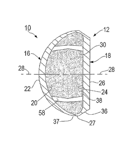
A first family of embodiments of accommodating intraocular lenses 10 of the
invention is
illustrated in FIGURES 1-4. FIGURE 5 shows an exemplary such lens implanted in
an eye.
Lens 10 includes a lens body 12, and first and second flanges 14. Lens body 12
includes a
convex anterior body member 16 and a generally planar posterior body member
18. Anterior body
member 16 has an inner surface 20 and an outer surface 22. Posterior body
member 18 has an
inner surface 24 and an outer surface 26. Anterior body member 16 and
posterior body member 18
are joined to each other at an outer perimeter 27 of the lens body.
A vision axis 28 extends through the lens body, generally centered with
respect to outer
perimeter 27 of the lens body. Vision axis 28 generally passes through the
apex of the convex arc
which is defined by anterior body member 16, and also passes through the
center of the posterior
body member. Thus vision axis 28 is generally centered on the lens body, and
passes front-to-rear
through the lens body, as through the center of the anterior body member and
the center of the
posterior body member.
As illustrated in FIGURES 1, 2, and 4, flanges 14 are connected to the lens
body at outer
perimeter 27, at opposing sides of the lens body, and extend from the lens
body in opposing
directions which are generally perpendicular to the direction of extension of
the vision axis or at a
small angle to such perpendicular, e.g. no more than 10 degrees.
Between the anterior body member and the posterior body member is a closed and
sealed
cavity 30 which is generally defined by the inner surfaces 20, 24 of the
anterior body member and
the posterior body member. In the illustrated embodiment, cavity 30 has a
cross-section which is
generally constant, or nearly constant, when turned about the vision axis.
Given the shapes of the
inner surfaces of the anterior and posterior body members, cavity 30 has a
cross-section which
generally resembles a hemisphere.
As illustrated in FIGURE 3, a cross-section of the arcuate inner surface of
anterior body
member 16 generally resembles a circular configuration. However, as is well
illustrated in
FIGURES 6 and 7, an arcuate inner surface of either or both of anterior body
member 16 or
posterior body member 18 can deviate substantially from a true circular, e.g.
hemispherical path.
Both FIGURES 6 and 7 illustrate compound arcuate paths where the radii of
curvature change
along the progression of the arcuate path of the respective inner surface 20
or 24. However, in
typical embodiments, a cross-section of the lens body reveals symmetry of the
arcuate inner
surface with respect to the vision axis.
7
= CA 02902676 2015-09-02
Referring to FIGURE 3, the configuration of the arcuate path of inner surface
20 is the
same as the configuration of the arcuate path of outer surface 22, off-set in
that the origins of the
arc segments in inner surface 20 are displaced along vision axis 28 from the
origins of the arc
segments in outer surface 22. Accordingly, and as illustrated in FIGURE 3, the
thickness of the
anterior body member is represented by relatively greater dimensions at
locations proximate the
vision axis and is represented by relatively lesser dimensions at portions 37
of the anterior body
member which are remote from the vision axis.
The thickness of the posterior body member is generally constant, and is
generally greater
than the thickness of the anterior body member, about the majority of the
projected area of the
posterior body member, namely all of the posterior body member except that
portion 36 of the
posterior body member which is remote from the vision axis.
The lens body can be made from material which comprises, for example and
without
limitation, a silicone composition such as is known for use in intraocular
lenses. Such silicone
composition is resiliently elastic and compressible, but retains good
restorative dimensional
memory. Other shell membrane materials can be used such as, for example and
without limitation,
polymerized collagen (Co!lamer, manufactured by Staar Surgical, Inc.),
Monrovia, California, elastic
acrylic polymers, combinations of collamer and hydroxyethyl methacrylate, and
other clear, e.g.
transparent, flexible bio-compatible materials well known in the art as being
suitable for use in
optical applications.
Cavity 30 is filled with optical liquid 38. Liquid 38 is a viscous liquid
which, in one
embodiment of the invention can be silicone oil which has a refractive index
of 1.4034, e.g. about
1.40, which material is known for use to fill the vitreous cavity in certain
cases of retinal detachment
and so is known to be bio-compatible. Optical liquid 38 does not contact the
natural bio-intraocular
structures of the eye, as the oil is enclosed entirely within the closed and
sealed cavity 30 of the
flexible lens body.
Other bio-compatible viscous materials, which can be used as the optical
liquid, include
chondroitin sulfate, hyaluronic acid and its hyaluronate salts, optionally
mixed with e.g. saline
solution, to obtain fairly precise desired refractive indices such as at or
above 1.4. A variety of other
viscous gels having suitable refractive index, can be used. Any such gel must
be visually
transparent, must have a refractive index greater than the refractive index of
water, e.g. above
about 1.33, and must be bio-compatible with respect to the use environment.
Given these rather
broad parameters, a substantial range of material compositions are acceptable
as the contained
interior substance.
The viscosity of optical liquid 38 is substantially greater than the viscosity
of water, but
liquid 38 must be sufficiently pliable to easily conform to any changes in
curvature of the adjacent
body member which may be urged on the lens body. In general, optical liquid 38
reflects the
character of a gel, while being readily deformable when so urged by the
anterior body member
8
CA 02902676 2015-09-02
and/or the posterior body member. Accordingly, liquid 38 typically has a
viscosity of about 4000
nnillipoise to about 7,000,000 nnillipoise, optionally about 30,000 to about
3,000,000 millipoise. One
known acceptable gel has a stated viscosity of 30,000 to 50,000 centistokes
(cSt). The viscosity
can, of course, be adjusted by incorporation, in the optical liquid, of
viscosity change agents known
to those skilled in the gel arts.
Optical liquid 38 can also have the quality of circular or orthogonal
birefringence.
Birefringence is the quality of materials wherein light of certain polarities,
either orthogonal as in
traditional polarizing lenses, or circular polarity, has two refractive
indices. Such birefringence can
be obtained by mixing two materials having the different, e.g. refringent
indices. Example of such
mixture is a mixture of dextro-rotary and levo-rotary biologic sugars and/or
amino acids. So long as
the two refractive indices differ by a significant amount, the lens is
birefringent, and thus bifocal.
Such lens focuses light of one polarity at a relatively greater distance, and
light of a different
polarity at lesser distances. Such birefringence increases the bifocal effect
of the lens, but is not
essential for lens function in this invention.
Lens body 12 can be fabricated with cavity 30 being empty. A sealable valve is
assembled
to the lens body, out of the line of sight of the eye, thus away from vision
axis 28. The gel is filled
into cavity 30 through the resealable valve.
The function of the lens, as an accommodating lens in this invention, depends
primarily on
the change in the arcuate shape of the lens body, which change occurs as an
act of
accommodation. The change in shape is provided by the combination of flexing
of the shell
material e.g. anterior body member 16, and fluidity of optical liquid 38 in
response to an action of
the ciliary muscle.
FIGURE 5 illustrates the lens of FIGURES 1-4 installed in a human eye 40, it
being
understood that lenses of the invention can also be installed in the eyes of
various animal species.
As illustrated in FIGURE 5, the natural lens has been removed, such as in a
cataract surgery.
The natural capsular bag 42, which previously enclosed the natural lens is
largely in place,
though part of the anterior portion of the natural bag has been removed in the
embodiment
illustrated in FIGURE 5.
Lens 10 is positioned such that distal edges 44 of flanges 14 are disposed
against the
inner surface 46 of the outer perimeter 48 of the capsule bag. The capsule bag
remains attached to
the ciliary muscle 50 through zonules 52. However, flanges 14, in the
embodiment illustrated, are
of sufficient length that the flanges expand the outer perimeter of the
capsule bag such that the
outer perimeter of the bag is proximate the ciliary muscle. Accordingly, even
modest contraction of
the ciliary muscle is effective to push against the distal edges of flanges
14.
Lens 10 generally works as follows. When the eye tries to focus on a near
object, the
ciliary muscle 50, illustrated in FIGURES 5 and 8, contracts inward, pushing
inward on the lens
zonules, and on the outer perimeter 48 of the capsule bag, while also raising
pressure in the
9
CA 02902676 2015-09-02
vitreous gel behind the lens. The centripetal force of the contracting ciliary
muscle is transmitted
inwardly, through the capsule bag to the distal edges of flanges 14, and
through flanges 14 toward
the vision axis, thus to reduce the e.g. diameter of outer perimeter 27 of the
lens body. As the size
of the outer perimeter of the lens body decreases, the maximum diameter of the
anterior body
member correspondingly decreases. The anterior body member is fabricated, in
the embodiment
illustrated in FIGURES 1-5, to be more readily flexed than the posterior body
member. Accordingly,
a disproportionate share of the flexing, which is imposed by the ciliary
muscle on flanges 14, is
absorbed by the anterior body member. The physical response of the anterior
body member is
expressed as an inward flexing of the remote portions 37 of the anterior body
member, e.g.
adjacent the outer perimeter of the lens body.
The inward flexing of the anterior body member at the outer perimeter is
accompanied by
generally reduced radius of curvature of anterior body member 16 as the
anterior body member
flexes to accommodate the reduction in diameter of the lens body at outer
perimeter 27. Such
reduction in radius of curvature of the anterior body member urges a
corresponding change in the
curvature of the surface of optical liquid 38 which is disposed at the inner
surface of the anterior
body member. Such resulting change in the configuration of optical liquid 38
generates a change in
the focal length of the lens. Such change in optical radius of curvature of
the working optics, in this
case optical liquid 38, changes the focal point of the lens in a
multiplicative fashion, via Snell' s law,
wherein
Power = (Difference in Indices) / (Radius of Curvature).
Lens assemblies which rely on linear e.g. translational, movement of a first
lens body with
respect to a second lens body, or simply movement of a lens body along the
vision axis, to provide
for change in focal length, rely on a linear relationship between the distance
of movement of the
lens body and the change in focal length.
By contrast, substantially greater multiplicative changes in focal length can
be achieved by
using the ciliary muscle to change primarily curvature of the lens rather than
to cause primarily
translation movement of the lens surfaces as in the conventional art. Thus,
where change in focal
length according to translational movement of the lens surfaces by action of
the ciliary muscle is
limited to about 1.5 diopters for a 1 mm translation of a lens, change in
curvature of lenses of the
invention, responsive to the same action of the ciliary muscle, can provide up
to about 3.5 diopters
change, optionally up to about 3 diopters change, further optionally up to
about 2.5 diopters
change, depending on the starting arcuate profile of the lens. The lens can,
of course, be designed
to deliver lesser degrees of change, such as up to about 2.0 diopters, or
less, as desired.
FIGURE 6 illustrates a second embodiment of accommodating intraocular lenses
of the
invention. In the lens of FIGURE 6, anterior body member 16 is convex as in
the embodiment of
FIGURES 1-5, thus to provide basis for efficient change in focal length with
change in activity of the
= CA 02902676 2015-09-02
ciliary muscle. Posterior body member 18 is, contrary to the embodiment of
FIGURES 1-5, mildly
concave, or recessed planar as shown, so as to accommodate e.g. a bulging
profile on the vitreous
humor, or where the depth of the lens cavity, between the vitreous cavity and
the natural iris 54 is
insufficient to properly receive a lens which is configured as in FIGURES 1-5
where the posterior
body member is planar, and not recessed. As in the embodiments of FIGURES 1-5,
both anterior
body member 16 and posterior body member 18 are shown to be symmetrical with
respect to the
vision axis.
FIGURES 7 and 8 show another modified version of the lenses of FIGURES 1-6.
The lens
of FIGURES 7 and 8 have flanges 14 which are designed to fit directly into the
ciliary sulcus 54,
e.g. directly against the ciliary muscle. In the assembly shown in FIGURE 8,
flanges 14 are outside,
e.g. in front of, the capsular bag, and in direct contact with the contracting
ciliary muscle 50.
Contraction of muscle 50 applies force directly onto flanges 14. Flanges 14
transmit the forces to
lens body 12, thus directly compressing the lens body at outer perimeter 27 of
the lens body.
Such compressing of the lens body at outer perimeter 27 shortens the radii of
curvature of
both the anterior body member and the posterior body member, and achieves a
high degree of
accommodation, potentially higher than any accommodation which would accompany
a
corresponding muscle contraction in connection with a lens of FIGURES 1-5, or
FIGURE 6.
Such increase in degree of accommodation results from the fact that both of
body
members 16 and 18 are convex. Namely, the convex nature of liquid 38 is
established at the inner
surface of the anterior body member as well as at the inner surface of the
posterior body member.
With convex curvature at both the anterior surface of liquid 38 and at the
posterior surface of liquid
38, light rays incident on the lens are treated to both a first anterior focal
length adjustment, and to
a second posterior focal length adjustment.
In general, placing flanges 14 in the sulcus is less preferred than placing
the flanges in the
capsule bag. However, in some instances, the lenses of FIGURES 1-6, wherein
only the anterior
body member is convex, are deficient in terms of the diopter adjustment which
can be achieved.
Where greater diopter power is required, the double-convex lens of FIGURE 7 is
available
to provide such optical power. However, where the double-convex lens of FIGURE
7 is selected, it
is quite possible that the front-to-back distance, between the vitreous
chamber and generally up to
the iris of the eye, may be too small to receive the front-to-back dimension
of the lens of FIGURE 7.
In such instance, flanges 14 are positioned relatively frontwardly in the lens
cavity, and are
positioned in the sulcus, in order that the back of the lens body be in front
of, e.g. displaced from,
the vitreous chamber, as illustrated in FIGURE 8. As illustrated in FIGURE 8,
in such instance, the
front of the lens may extend frontwardly of the natural iris 56.
Still referring to the embodiments of FIGURES 7 and 8, compressing one or both
of the
body members 16, 18, at outer perimeter 27, shortens the radius of curvature
of the anterior body
11
= CA 02902676 2015-09-02
member and the posterior body member, both generally about vision axis 28,
whereby the shape of
the lens is reconfigured more toward a spherical shape.
The forces of ciliary contraction during accommodation may not transmit
directly through
zonules 52 to the capsular bag. The zonules are a loose network of fibers, and
so the zonules
might slacken when the ciliary body contracts. The exact mechanism of
operation of zonules is still
not fully settled among ophthalmologists and physiologists.
Figure 9 shows, as a further embodiment, a relatively larger lens, which fits
snugly within
the capsular bag. This lens has anterior 16 and posterior 18 body members
enclosing viscous
optical liquid 38, but is devoid of flanges 14. Inside the lens body are first
and second struts 58.
Struts 58 can optionally extend 360 degrees around vision axis 28, either
intermittently, or as a
single continuous strut body, on the interior of the shell. Struts 58 are
resiliently compressed front-
to-rear when the ciliary muscle is relaxed, and in the non-accommodating
state. As the ciliary
muscle contracts, the restorative forces in struts 58 push the anterior and
posterior body members
away from each other, front-to-rear, thus to accommodate near vision. The
design of the strut
allows the strut to bend only outward, away from vision axis 28. This action,
of pushing the anterior
and posterior body members away from each other, shortens the radius of
curvature of e.g. the
anterior body member in a fashion similar to natural shortening of the radius
of curvature,
accommodation, in a natural lens.
Calculations of the needed curvatures of the anterior and posterior optical
surfaces of the
anterior 16 and posterior 18 body members, to enable focusing of light at
distance when the eye is
in a relaxed state can be realized using the matrix system of optical
calculations which are
described, for example, by Langenbucher et al in Ophthal. Phyisol. Opt. 2004
24:450-457.
In all of the lens embodiments of FIGURES 1-9, the outer body members 16 and
18 are
thinnest at or adjacent outer perimeter 27 of lens body 12, optionally
proximate flange 14 in the
embodiments of Figures 1-8. Forces from the ciliary muscle are transferred
through flanges 14 to
body members 16, 18. Given the relatively thinner portions of the body members
proximate flanges
14, the body members flex to a greater extent proximate flanges 14 than
farther away from the
flanges, and thereby shorten the radius of curvature of the optical surfaces
of body members 16,
18, thereby to effect diopter change in the lens body primarily through
corresponding curvature
changes in the contained optical liquid 38.
In the embodiments of Figures 1-5, posterior body member 18 is substantially
flat, planar,
and thus lacks any optical power. The posterior body member is also thicker
than the anterior body
member in such embodiments, whereby the degree of change in curvature of the
anterior body
member, expressed as distance of translation of the anterior body member
perpendicular to the
profile of the anterior body member, is substantially greater than the degree
of change, if any, in
the curvature in the posterior body member. The embodiments of FIGURES 3 and 6
may enable
12
CA 02902676 2015-09-02
transmission of the pressure rise in the posterior vitreous chamber to assist
in changing the
anterior radius of curvature, thereby increasing near focusing, namely
accommodating, power.
The function of lens 10 as an accommodating lens depends primarily on the
change in
shape of the lens as the act of accommodation. When the e.g. human eye tries
to focus on a near
object, the ciliary muscle contracts inward, pushing inward on the lens
zonules, and also raising
pressure in the vitreous chamber which is behind the lens. The centripetal
force of the contracting
ciliary muscle is transmitted through the lens flange 14, compressing the lens
body at outer
perimeter 27. Compressing the lens body at outer perimeter 27 shortens the
radius of curvature of
the anterior body member in the embodiments of FIGURES 1-6, and shortens the
radius of
curvature of both the anterior and posterior body members in the embodiment of
FIGURES 7 and
8. In all of the lens embodiments of FIGURES 1 through 8, the lens body is
relatively thinner at the
juncture of the anterior and posterior shells with flange 14, e.g. at outer
perimeter 27. In this
scenario, the forces received from flanges 14 are absorbed largely in
shortening the radius of
curvature of the optical surfaces, rather than largely being absorbed in
translation of the anterior
body member further away from the posterior body member.
This is in contrast to translation of the body members where the power changes
depend on
position in the eye and axial length of the eye. For this reason, the lenses
of the invention offer
greater diopter ranges than lenses which operate according to translation of
one or more of the
lens elements.
As indicated above, with the exception of the embodiments of FIGURE 9, the
force of the
ciliary muscle is received at distal edges 44 of flanges 14. The muscle force
is transmitted through
flanges 14 toward lens body 12, and is received at lens body 12 at or adjacent
outer perimeter 27.
Such force acts, through outer perimeter 27, on the lens body to re-shape the
curvature of the
anterior and/or posterior body members, thus to effect change in focal length
of the lens body.
Thus it is critical that the flanges, where used, have sufficient rigidity
that the contraction
forces of the ciliary muscle are transmitted to the lens body in sufficient
intensity to effect
accommodation of the lens body in accord with the accommodative vision needs
being expressed
by the ciliary muscle.
To that end, flanges 14 can be specified in terms of thickness "T" sufficient
to provide the
required level of rigidity which is effective to transmit the ciliary muscle
forces. The particular
dimension of thickness "T" depends on the rigidity of the material composition
selected for flange
14, and can be well selected by those skilled in the art.
In the alternative, the composition of the material used to make flanges 14
can be different
from the material used to make lens body 12. Thus, the material used to make
flanges 14 can be
more rigid than the material used in making body members 16, 18, thus to
achieve rigidity by
material selection.
13
CA 02902676 2015-09-02
As used herein "optical liquid" includes gels, which might not otherwise be
considered
liquids, to the extent the shape of the gel mass can be readily changed by
action of the ciliary
muscle. Thus, "optical liquid" does include gel compositions which have
viscosity similar to the
viscosity of the lens matrix in a youthful natural eye.
The following matrix calculations are performed using the model eye and its
parameters as
developed by Gullstrand. The measurements are taken from the average distances
and radii of
curvature of the Gullstrand Model Eye.
Radius of Curvature.Translation Distances
Indices of Refracton
(meters) of Eye (Meters)
Surfaces
(0.0078'N ComeaExterior ( 1.000 \ Air Cornea
(0.00055'
0.0065 Cornea Interior 1.3771 Cornea Ant. Chamber 0.003
0.009 IOL Anterior 1.3374 Aqueous Lens Thickness 0.003
0100 IOL Posterior 1.4034 Silicone
Oil Vitreous 0.01821
4.336 Vitreous t 0
11,:= :=
00 0 0
0 0 0
0 0 0
0 0 0
= 0 / \ 0 ) 0
The above "R", "N", and "t" vectors are referenced by their respective
indices as follows
Ni ¨ No tO
Pel := _____________________________ De := Vit t3
RO N1
N2 ¨ NI
Pc2 :=
RI N2
N4 ¨ N3 t2
Pi2 ________________________________________
R3 N3
14
CA 02902676 2015-09-02
, .
Any lens system, including the eye, can be calculated using a series of
multiplied matrices, with the first refracting surface, in the case of the
invention
the exterior of the cornea on the far right, followed by a translation matrix
with
reduced distance De, then the next surface, namely the posterior cornea, right
to
left
(1 Pi2) 01
F I -Pi I ) ( 1 0).( I -Pc2) 0) (1
-Pc1)] The basic
Sys :=
0 1 ) Di 1 1 Da 1 0 1 Dc 1 0 1 System
Expanding this matrix into a single product matrix can provide the
equation illustrated as FIGURE 10.
Solving that equation for Pi 1: =1,
and given the second focal point as Vit (t3), provides the equation
illustrated in FIGURE 11
Find (Pi) = 18.34277 This is the refracting power of the
anterior
surface of the intraocular lens.
N3 - N2
Ri1 By Snell' s Law
18.343
Ri1 = 0.0036 Radius of anterior lens surface at rest (in meters)
If the optic is 0.006m in diameter, then the angle of arc is: := 0 rad
Given
sin(cc) = (0Ø03)
Find ( )=0.98591 0.003
Radians = 0.83333 rad
0.0036
180
0.986 ____________________ = 28.24682 degrees in the relaxed state
2.
The half length on the arc 12 : = Ri1 Ø986
12 = 0.00355 (meters, )or 12x1000- = 3.54773 mm
Suppose the lens pinches with accommodation 0.0005 meters, or 0.5 mm total
- since the arc length has to be constant, the new angle of the half arc is
: =0
CA 02902676 2015-09-02
Given that
12. sin ( )
_______________________________ = 0.00275
Find( ) = 1.2045
The new radius is
0.00275
R6 := _________________________
Sin(1.20451-ad)
R6 = 0.00295
N3 - N2
Power2 :
R6
Power2 = 22.40785 This is the power attainable in accommodation
Power2 - 18.3472 = 4.06065 This small change in curvature yields 4
diopters of accommodation
Those skilled in the art will now see that certain modifications can be made
to the
apparatus and methods herein disclosed with respect to the illustrated
embodiments. And while
the invention has been described above with respect to the preferred
embodiments, it will be
understood that the invention is adapted to numerous rearrangements,
modifications, and
alterations.
The scope of the claims should not be limited by the preferred embodiments set
forth in the
examples, but should be given the broadest interpretation consistent with the
description as a
whole.
16