Note: Descriptions are shown in the official language in which they were submitted.
CA 02903066 2015-08-28
WO 2D14/165750 PCMS2014/032963
VERTICALLY STOWED TRAY TABLE ASSEMBLY
WITH TRANSLATIONAL MOVEMENT
TECHINCAL FIELD AND BACKGROUND OF THE INVENTION
[0001] The present invention relates generally to the field of tray table
assemblies
associated with passenger seats, and more particularly, to a tray table
configured to slide
along a rail adjacent a seat and move between a stowed vertical orientation
alongside a
seatbaelc and a deployed horizontal position forward of the seatback,
[0002] Tray tables are associated with most every type and class of
aircraft seat to
provide a passenger with a flat, horizontal tabletop for working, dining, etc.
Tray tables are
typically configured to move between o stowed position when not in use, such
as during taxi,
takeoff and landing, and a deployed position for use during flight, in coach
class seating, tray
tables are often attached to the back of a forward seat and pivot downward to
horizontal for
use by a passenger in the next row, In seating arrangements in which there are
no forward
seats, tray tables commonly stow within a vertical pocket alongside the seat,
and thus require
complex hinge assemblies and armatures to lift, pivot and rotate the tabletop
into place over
the passenger's lap.
[0003] In either of the aforementioned seating arrangements, conventional
tray
tables are typically required to be stowed to permit ingress/egress from the
seat, Stowing the
tray table requires changing the horizontal orientation of the tabletop, which
requires the
passenger to remove their articles beforehand, This is particularly
inconvenient when the
passenger intends on only briefly getting up, for example, to use the
lavatory, or when the
tabletop is supporting food and beverages that are difficult to store
elsewhere. Tray tables
that store alongside the seat within a vertical pocket are also
disadvantageous in that a storage
compartment adds complexity and weight, and consumes valuable floor and seat
space.
CA 02903066 2015-08-28
WO 2014/165750 PCT/US2014/032963
[0004] Accordingly, what is needed is a tray table configured to move
when
deployed to permit egress withont having to be stowed, as well as a tray table
that stows
within space not presently utilized for another purpose. Such a tray table
would enhance
passenger comfort and convenience and maximize the use of limited space in the
aircraft
cabin.
BRIEF SUMMARY OF THE INVENTION
[0005] In a first embodiment, provided herein is a tray table assembly
for a
passenger seat including a seatback and a seat bottom. The tray table assembly
generally
includes a horizontal rail arranged alongside the passenger seat having a
length extending
from the seatback to a position forward of the seat, a carriage assembly
configured to travel
horizontally along the length of the horizontal rail, and a tray table
attached to the carriage
assembly, the tray table configured to pivot between a vertical orientation in
which the tray
table is stowed alongside the seatback and a horizontal orientation in which
the tray table is
positioned forward of the seatbaek.
[0006] In a further embodiment, the tray table assembly may include a
second
horizontal rail arranged parallel to and continuous with the horizontal rail,
the carriage
assembly configured to travel simultaneously along both rails.
[0007] In a further embodiment, the tray table assembly may include a
ledge
arranged parallel to and vertically below the horizontal rail, the ledge
continuous along a
'portion of the length of the horizontal rail such that the ledge interferes
with the carriage
assembly to prevent the carriage assembly from lowering until the carriage
assembly is
forward and clear of the ledge.
[0008] In a further embodiment, the tray table assembly may include a
housing
within which the horizontal rails and the ledge are housed.
2
CA 02903066 2015-08-28
WO 2014/165750 PCT/US2014/032963
[0009] In a further embodiment, the carriage assembly may include one of
a
linear-motion bearing, a rolling element bearing, a roller slide, a plain
bearing and a roller for
sliding movement along the length of the horizontal rail.
[0010] In a further embodiment, the tray table assembly may include a
support
member and a support beam, the support member pivotally attached to the
carriage assembly
and the support beam, the support beam supporting the tray table in a
horizontal cantilevered
orientation, and the support beam configured to slide vertically along the
carriage assembly
such that as the tray table pivots toward horizontal the support beam lowers
vertically and
pivots to an angle to vertical.
[0011] In a further embodiment, the carriage assembly may include a gas
spring
arranged to provide a spring force for lifting the tray table for stowing, and
the gas spring
may be sized such that the spring force cancels out force from the tray
table's center of
gravity when the tray table is at 45 degrees to horizontal.
[0012] In a further embodiment, the tray table assembly may include a
damper
arranged to control tray table rotation during deployment.
[0013] According to a second embodiment of the invention, an aircraft
passenger
seat is provided herein including a seat bottom and a seatback, and a tray
table asserribly
arranged alongside the seat. The tray table assembly includes a horizontal
rail arranged
alongside the passenger seat having a length extending from the seatback to a
position
forward of the scat, a carriage assembly configured to travel horizontally
along the length of
the horizontal rail, and a tray table pivotally attached to the carriage
assembly configured to
pivot between a vertical orientation in which the tray table is stowed
alongside the seatback
and a horizontal orientation in which the tray table is positioned forward of
the seatback,
3
CA 02903066 2015-08-28
WO 2014/165750 PCT/US2014/032963
[0014] In a further embodiment, the tray table assembly may include a
second
horizontal rail arranged parallel to and continuous with the first horizontal
rail, the carriage
assembly configured to travel simultaneously along both rails,
[0015] In a further embodiment, the tray table assembly may include a
ledge
arranged parallel to and vertically below the horizontal rail, the ledge
continuous along.a
portion of the length of the horizontal rail such that the ledge interferes
with the carriage
assembly to prevent the carriage assembly from lowering until the carriage
assembly is
forward and clear of the ledge. =
[0016] In a further embodiment, the tray table assembly may include a
housing
positioned alongside the seat within which the horizontal rails and the ledge
are housed.
[0017] In a fbrther embodiment, the tray table assembly may include a
support
member and a support beam, the support member pivotally attached to the
carriage assembly
and the support beam, the support beam supporting the tray table in a
horizontal cantilevered
orientation, and the support beam configured to slide vertically along the
carriage assembly
such that as the tray table pivots toward horizontal the support beam lowers
vertically and
pivots to an angle to vertical.
[0018] In a further embodiment, the tray table assembly may include a gas
spring
arranged to provide a spring force for lifting the tray table for stowing, and
a damper
arranged to control tray table rotation during deployment,
[0019] Embodiments of the invention can include one or more or any
combination
ofthe above features and configurations.
[0020] Additional features, aspects and advantages of the invention will
be set
forth in the detailed description which follows, and in part will be readily
apparent to those
skilled in the art from that description or recognized by practicing the
invention as described
herein, It is to be understood that both the foregoing general description and
the following
4
WO 2014/165750
PCT/US2014/032963
detailed description present various embodiments of the invention, and are
intended to
provide an overview or framework for understanding the nature and character of
the
invention as it is claimed. The accompanying drawings are included to provide
a further
understanding of the invention.
BRIEF DESCRIPTION OF THE DRAWINGS
[0021] Features, aspects and advantages of the present invention are
better
understood when the following detailed description of the invention is read
with reference to
the accompanying drawings, in which:
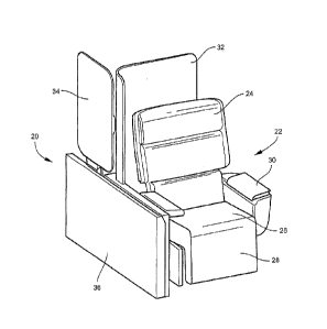
[0022] FIG. 1 is an isometric view of a tray table assembly according
to an
embodiment of the invention associated with an aircraft passenger seat;
[0023] FIG. 2 is another isometric view of the tray table assembly
and associated
seat showing the tray table stowed vertically alongside the seatback;
[0024] FIG. 3 shows the tray table slid forward along the rail and in
a vertical
orientation;
[0025] FIG. 4 shows the tray table deployed horizontally;
[0026] FIG. 5 shows the tray table deployed horizontally and moved
horizontally
forward apart from the seat;
[0027] FIG. 6 is an overhead view showing the tray table moved
horizontally
forward apart from the seat to permit egress from the seat;
[0028] FIG. 7 is an isometric view of the horizontal rail arrangement
upon which
the tray table slides alongside the seat;
[0029] FIG. 8 is an isometric view of the tray table and carriage
assembly;
[0030] FIG. 9 is a detailed view of the tray table and carriage
assembly of FIG. 8;
[0031] FIG. 10 details carriage and tray table movement; and
CA 2903066 2017-11-20
CA 02903066 2015-08-28
WO 2014/165750 PCTfUS2014/032963
[0032] FIGS, 1 IA-C are sequential views illustrating tray table
deployment from
a vertical orientation to a horizontal orientation,
DETAILED DESCRIPTION OF THE INVENTION
[0033] The present invention will now be described more fully hereinafter
With
reference to the accompanying drawings in which exemplary embodiments of the
invention
are shown. However, the invention may be embodied in many different forms and
should not
be construed as limited to the representative embodiments set forth herein,
The exemplary
embodiments are provided so that this disclosure will be both thorough and
complete, and
will fully convey the scope of the invention and enable one of ordinary skill
in the art to
make, use and practice the invention. Like reference numbers refer to like
elements
throughout the various drawings,
[0034] Referring to FIGS, 1-6, a tray table assembly according to an
embodiment
of the invention is shown generally at reference numeral 20, The tray table
assembly 20 is
shown arranged alongside an aircraft seat 22 for use by a seated passenger,
The seat 22 can
be any type of seat, for example, a coach class seat limited to a shallow
recline or a premium
class seat configured to move between upright and lie flat sitting positions.
The seat 22
generally includes a seatback 24, scat bottom 26, a legrest 28 and armrests
30, each of which
may move independently or cooperatively to achieve various sitting positions.
The seat 22
may be part of a row of laterally adjacent seats, a group of nested seats
and/or suites, or an
isolated scat, among other seat types. As shown, a partition or privacy shell
32 is positioned
behind the seat 22. The tray table assembly 20 is positioned alongside the
seat 22, aligned
substantially parallel to the longitudinal axis of the scat, The entire tray
table assembly 20
has a length about equal to or longer than the seat 22 such that the tray
table 34 can travel
horizontally from a stowed position alongside or slightly behind the seat back
24 to a
deployed horizontal position forward of the seat 22, as described in detail
below,
6
CA 02903066 2015-08-28
WO 2014/165750 PCT/US2014/032963
[0035] As shown in FIGS, l and 2, the tray table 34 is configured to stow
vertically, or substantially vertically, alongside the seatback 24 at a height
vertically above
the armrest 30. In the stowed position, the tray table 34 occupies the space
between the
seatback 24 and the interior wall of the aircraft, or the space between
adjacent seatbacks,
neither of which have been utilized for tray table storage prior to the
present invention.
Space permitting, the tray table 34 may be vertical when fully stowed
alongside the seatback
24. In seating arrangements in which the curvature of the interior wall and
the length of the
tray table 34 do not allow the tray table to be stowed vertically, the tray
table may be stowed
at a slight angle to vertical. The tray table 34 may optionally lean against
the interior wall or
seatback 24 when fully stowed, The tray table assembly 20 may be secured to
and suppoited
by one or more of the interior wall of the aircraft, the seat frame and the
privacy shell 32,
[0036] The tray table assembly 20 generally includes the tray table 34, a
housing
36 housing at least one horizontal rail, and a carriage assembly 44 for moving
the tray table
along the rail, as described in detail below. The housing 36 may be stationary
or configured
to travel (e.g., slide) horizontally alongside the seat 22, The carriage
assembly 44 is
configured to travel horizontally (e.g., slide) along the length of the
horizontal rail and rotate
the tray table 34 between vertical and horizontal. Thus, the housing 36 may
translate forward
and rearward relative to the seat 22, and the carriage assembly translates
relative to the
housing 36, canying the tray table 34 along therewith. The length of travel of
the housing 36
and/or carriage assembly 44 may depend on one or more seat length, the extent
of seat
recline, and the amount of available space forward and rearward of the seat
22, among other
factors. The housing length and shape may be customized based on the
installation location,
the shape of the interior wall, the amount of available space between the seat
and the interior
wall, the amount of space between seats, the seat type and frame, etc.
7
CA 02903066 2015-08-28
WO 2014/165750 PCT/1JS2014/032963
10037] Referring to FIGS. 3 and 4, the tray table 34 is deployed by
sliding the tray
table and/or housing 36 forward relative to the seat 22, such as via automatic
linear actuation
when commanded, such as by an input from the passenger through a passenger
control unit.
In the embodiment in which the housing 36 slides, the housing 36 may slide
forward a first
portion of the way and the tray table 34 the remaining portion. Once the
supporting carriage
assembly 44 has traveled horizontally forward along the rail an amount
sufficient to clear any
underlying obstruction, as described below, the tray table 34 is able to
deploy horizontally.
[00381 Referring to FIGS. 5 and 6, once the tray table 34 is deployed,
the carriage
assembly 44 is able to travel horizontally a predetermined distance to
position the tray table
34 apart from the seat to permit egress from the seat without having to stow
the tray table.
[00391 Referring to FIG. 7, the housing 36 houses a first horizontal rail
38, a
second horizontal rail 40, and a ledge 42, The first and second rails 38, 40
are arranged
parallel to one another and each have a length that extends from the seatback
24 to a position
forward of the seat 22. The spaced rail arrangement may be provided to prevent
the tray table
from twisting, and the rails may be continuous such that the carriage assembly
travels along
both simultaneously. The length of the rails may be customized depending on
the desired
length of travel and amount of available space forward of the scat 22.
f0040) The ledge 42 is arranged parallel to and vertically below the
first
horizontal rail 38. The ledge 42 is continuous along a portion of the length
of the first
horizontal rail 38 from the seatback 24 forward, but stops short of extending
to the forward
end of the first horizontal rail 38. In this arrangement, the ledge 42
functions to interfere with
the carriage assembly 44 along the coextensive portions of the first
horizontal rail 38 and
ledge 42 to prevent the carriage assembly 44 from lowering vertically to
deploy the tray table
34 horizontally, Once the carriage assembly 44 travels forward beyond the
ledge 42, the
carriage assembly 44 is free to lower to rotate the tray table toward
horizontal, This
8
CA 02903066 2015-08-28
WO 2014/165750 PCT/US2014/032963
arrangement is advantageous because the ledge 42 prevents the tray table 34
from deploying
toward horizontal too early and falling on the seated passenger,
[0041] Referring to FIGS, 8-10, the tray table 34 is supported and
carried by the =
carriage 44. The carriage assembly may include a first portion and a second
portion that
align vertically beyond the ledge 42 to allow the tray table 34 to deploy
horizontally. The
carriage assembly 44 travels horizontally along the length of at least the
first horizontal rail
38. Guide blocks 50 on the backside of the carriage assembly 44 engage with
and travel
horizontally along their respective rail. Sliding movement of the guide blocks
50 along the
rails 38, 40, as well as sliding movement of the housing 36 relative to the
floor, may be
achieved using any form of linear slide for guiding motion in at least one
dimension, which
may include, for example, a linear-motion bearing, a rolling element bearing,
a roller slide, a
plain bearing, a roller, etc.
[0042] The tray table 34 attaches on its underside to a support member
52. The
support member 52 is pivotally attached at one end to the carriage assembly 44
and pivots
about pivot point 54 to move the tray table between the vertical and
horizontal positions. A
support beam 56 supports the tray table 34 in its horizontal, cantilevered
position. The
support beam 56 is pivotally attached to the carriage assembly 44 at a first
end and to the
support member 52 at a second end. The support beam 56 further slides
vertically relative to
the carriage assembly 44 such that as the tray table moves in the direction
toward horizontal,
the first end of the support beam 56 moves vertically downward with respect to
the carriage
assembly 44 and the second end of the support beam 56 moves outward with
respect to the =
carriage assembly 44, When the tray table 34 is horizontal, the support beam
56 is at angle to
vertical to brace the tray table from below, Referring to FIG, 10, traction
gas springs 58
provide a spring force in the direction indicated by arrows 60 to facilitate
lifting the tray table
for stowing, The support beam 56 may rest on stops 66 when the tray table 34
is fully
9
CA 02903066 2015-08-28
WO 2014/165750 PCTAIS2014/032963
deployed, which takes the gas springs 58 out of the load path. Deployment
motion may be
controlled by a motorized linear actuator, in which case the gas springs are
not necessary.
[00431 Referring to FIGS, I IA-C, the gas springs may be sized such that
the gas
spring forces cancel out the force from the tray table's center of gravity
when the tray table
34 is at approximately 45 degrees. This creates a tipping point above which
the tray table 34
wants to rotate toward the stowed vertical position and below which the tray
table wants Co
rotate to the deployed horizontal position, As shown in FIG, 11A, in the
stowed position, the
force from the tray table's center of gravity is vertically downward as
indicated by directional
arrow 70, and the force from the gas spring is vertically upward as indicated
by directional
arrow 72. The moment generated by the tray table's center of gravity is weaker
than the
moment generated by the force from the gas springs above abOut 45 degrees,
thus the tray
table 34 wants to rotate toward the stowed position. As shown in FIG, 1113,
these forces 70,
72 cancel each other out at about 45 degrees such that no tray table
rotational moment is
created at the pivot point 54, As shown in FIG. 15C, the moment generated by
the tray
table's center of gravity overwhelms the gas springs below about 45 degrees,
and the tray
table 34 rotates toward the deployed horizontal position.
[00441 As best shown in FIG, 7, tray table rotation during deployment may
be
controlled by a linear speed control damper and/or brought to a controlled
stop with a shock
absorber, such as a hydraulic shock absorber 74 as shown.
[0045] The tray table 34 may be grabbed and manipulated to move and deploy
it,
Pivoting range of motion of the tray table 34 may be about 90 degrees, for
example. The
assembly 20 may further includes a release mechanism, latch, lock or automated
assistance
for moving, stowing, releasing and locking the tray table in either the
deployed or stowed
positions,
CA 02903066 2015-08-28
WO 2014/165750 PCT/US2014/032963
[0046] While preferred embodiments of a vertically stowed and translating
tray
table assembly are described above, it is apparent that various details of the
invention may be
changed without departing from the scope of the invention. Furthermore, the
foregoing
description of the embodiments of the invention and the best mode for
practicing the
invention are provided for the purpose of illustration only and not for the
purpose of
=
11