Note: Descriptions are shown in the official language in which they were submitted.
CA 02903102 2015-08-31
WO 2014/146191 PCT/CA2013/050238
1
AMIDE BRANCHED AROMATIC GELLING AGENTS
TECHNICAL FIELD
[0001] This document relates to amide branched aromatic gelling agents.
BACKGROUND
[0002] Benzamide gelling agents have been proposed or used in LCD displays
and as amide
nucleating agents. Pyromellitamide gelling agents have been proposed or used
in tissue engineering, drug
delivery, LCD displays, and catalysis.
SUMMARY
[0003] A downhole fluid is disclosed comprising a base fluid and a gelling
agent with an aromatic
core of one or more aromatic rings, the gelling agent having two or more amide
branches distributed about
the aromatic core, each of the two or more amide branches having one or more
organic groups.
[0004] A downhole fluid is disclosed comprising a base fluid and a
pyromellitamide gelling agent.
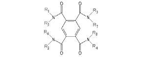
The pyromellitamide gelling agent may have the general formula of:
00
R1 iv 11 R3
R7
.)
F'.
Pt
N. .;
IR2 II [i
[0005] with RI, R2, R3, R4, R5, R6, R7, and Rg each being a hydrogen or an
organic group.
[0006] A method is also disclosed comprising introducing the downhole fluid
into a downhole
formation. A method of making a downhole fluid is also disclosed, the method
comprising: combining the
base fluid and gelling agent. A composition for gelling a downhole fluid is
also disclosed, the composition
comprising a amide branched aromatic gelling agent and a wetting agent.
[0007] A gelling agent is also disclosed for a downhole fluid, the gelling
agent having the general
formula of:
o
R1 J1 II F.
R, R-
P. ====
F1
12 P.
0 0
CA 02903102 2015-08-31
WO 2014/146191 PCT/CA2013/050238
2
[0008] with RI, R2, R3, R4, R5, R6, R7, and Rg each being a hydrogen or a
C7-24 alkyl group.
[0009] In various embodiments, there may be included any one or more of the
following features:
Each of the amide branches is connected to the aromatic core via a carbon-
carbon or carbon-nitrogen bond.
One or more of the amide branches are connected to the aromatic core via a
carbon-nitrogen bond. Each of
the amide branches is connected to the aromatic core via a carbon-nitrogen
bond. Three or four amide
branches are present. Each organic group is an alkyl group. Each alkyl group
is a straight chain alkyl group.
Each alkyl group has 6-24 carbon atoms. The aromatic core is benzene. Each of
the amide branches are
connected to the aromatic core via a carbon-nitrogen bond, and each organic
group is an alkyl group with 6-
24 carbon atoms. One or more of the amide branches is connected to the
aromatic core via a carbon-carbon
bond and one or more of the amide branches are connected to the aromatic core
via a carbon-nitrogen bond.
Each alkyl group has 6-12 carbon atoms. The aromatic core is naphthalene. Each
of the amide branches has
one organic group. The gelling agents exclude pyromellitamide gelling agents.
The gelling agent is a
pyromellitamide gelling agent.The pyromellitamide gelling agent has the
general formula of:
0 0
R1
N/R3
R5/
R6
\ 411 /R
/N
R2 R4
with RI, R2, R3, R4, R5, 126, R7, and R8 each being a hydrogen or an organic
group. R5, R6, R7, and R8 are each
hydrogens and one or more of RI, R2, R3, and R4 is each an alkyl group. K1,
K2, R3, and R4 are each alkyl
groups. R1= R2= R3 = R4. R1, R2, R3, and R4 each has at least 6 carbon atoms.
Each alkyl group has 6-24
carbon atoms. Each alkyl group has 6-10 carbon atoms. Each alkyl group is one
or more of straight chain,
branched, aromatic, or cyclic. Each alkyl group is straight chain. R5, R6, R7,
and R8 are each hydrogens, and
RI, R2, R3, and R4 are each straight chain alkyl groups with 6-10 carbon
atoms. RI, R2, R3, and R4have 6
carbon atoms. The base fluid comprises hydrocarbons. The hydrocarbons have 3-8
carbon atoms. The
hydrocarbons have 3-24 carbon atoms. The hydrocarbons comprise liquefied
petroleum gas. The base fluid
comprises one or more of nitrogen or carbon dioxide. A breaker is used or
present. The breaker is a water-
activated breaker and the downhole fluid comprises a hydrate. The breaker
further comprises an ionic salt.
The ionic salt further comprises one or more of a bromide, a chloride an
organic salt, and an amine salt. The
breaker comprises one or more of an alcohol or alkoxide salt. The one or more
of an alcohol or alkoxide salt
has 2 or more carbon atoms. The alkoxide salt is present and comprises
aluminium isopropoxide. The
alkoxide salt is present and the downhole fluid comprises a hydrate. The
breaker comprises a salt of
piperidine and the downhole fluid comprises a hydrate. The breaker further
comprises a coating. The coating
CA 02903102 2015-08-31
WO 2014/146191 PCT/CA2013/050238
3
further comprises wax. The downhole fluid is for use as a drilling fluid. The
downhole fluid is for use as a
downhole treatment fluid. Introducing the downhole fluid into a downhole
formation. Fracturing the
downhole formation. Recovering downhole fluid from the downhole formation, and
recycling the recovered
downhole fluid. Recycling further comprises removing a breaker from the
recovered downhole fluid. The
pyromellitamide gelling agent is provided with a carrier. The carrier
comprises glycol. The pyromellitamide
gelling agent is provided with a wetting agent. The pyromellitamide gelling
agent is provided with a
suspending agent. Combining is done on the fly before introducing the downhole
fluid into a downhole
formation.
[0010] These and other aspects of the device and method are set out in the
claims, which are
incorporated here by reference.
BRIEF DESCRIPTION OF THE FIGURES
[0011] Embodiments will now be described with reference to the figures, in
which like reference
characters denote like elements, by way of example, and in which:
[0012] Fig. 1 illustrates hydrogen bond formation.
[0013] Fig. lA shows the basic structure of an amide branched aromatic
gelling agent.
[0014] Fig. 1B shows on the left and right an amide branch connected to the
aromatic core via a
carbon-nitrogen bond and a carbon-carbon bond, respectively.
[0015] Fig. 2 illustrates a proposed solvation interaction between an alkyl
solvent and a
pyromellitamide gelling agent with straight chain allcyl groups.
[0016] Table 1: Characteristics of viscosity testing of disclosed gelling
agents. Viscosity testing was
carried out a Brookfield viscometer. TB, TH, TO and TD refer to N,N',N",1\l'"-
tetrabutylbenzene-1,2,4,5-
tetracarboxamide (TB), N,Nt,N",1\11"-tetrahexylbenzene-1,2,4,5-
tetracarboxamide (TII), N,N',N",N"-
tetraoctylbenzene-1,2,4,5-tetracarboxamide (TO), and N,N,N",N"'-
tetradecylbenzene-1,2,4,5-
tetracarboxamide (TD), respectively.
Fig. Gelling Agent Gelling Agent Solvent Shear Rate
Temperature
Concentration (mM) (sec) ( C)
3 TH 10 TG740 100 varying
4 TO 10 T0740 100 varying
TD 10 T0740 100 varying
6 TB 10 Cyclohexane 100 varying
7 TB 7 Cyclohexane 100 varying
8 TB 5 Cyclohexane 100 varying
CA 02903102 2015-08-31
WO 2014/146191
PCT/CA2013/050238
4
9 TB 4 Cyclohexane 100 varying
JO TB 3 Cyclohexane 100 varying
11 TB 2 Cyclohexane 100 varying
12 TB 1 Cyclohexane 100 varying
13 TH 7 TG740 100 varying
14 TH 5 TG740 100 varying
15 TH 4 TG740 100 varying
16 TH 3 TG740 100 varying
17 TH 2 TG740 100 varying
18 TH ' 1 T0740 100 varying
19 TO 7 TG740 100 varying
20 TO 5 TG740 100 varying
21 TO 4 TG740 100 varying
22 TO 3 TG740 100 varying
23 TO 2 TG740 100 varying
24 TO 1 TG740 100 varying
25 TD 7 TG740 100 varying
26 TD 5 TG740 100 varying
27 TD 4 TG740 100 varying
28 TD 3 TG740 100 varying
29 TD 2 TG740 100 varying
30 TD 1 TG740 100 varying
31 TH:TO 2:2 T0740 100 varying
32 TH:TO 2:2 T0740 100 varying
33 TO:TD 2:2 TG740 100 varying
34 TO:TD 2:2 T0740 100 varying
35 TH:TD 2:2 TG740 100 varying
36 TB 7 Cyclohexane 100 25
37 TB 7 Cyclohexane 400 25
38 TB 7 Cyclohexane 500 25
39 TB 7 Cyclohexane varying 25
[0017] Fig. 40 is a
graph of the data from Fig. 39, illustrating viscosity at different shear
rates.
CA 02903102 2015-08-31
WO 2014/146191 PCT/CA2013/050238
[0018] Fig. 41 is a graph of shear rate v. shear stress from the data of
Fig. 39, illustrating non-
newtonian behavior.
[0019] Fig. 42 is a graph of viscosity v. concentration for TB in
cyclohexane. =
[0020] Fig. 43 is an illustration of various pyromellitamide rotamers.
[0021] Fig. 44 is an 1H NMR spectrum for TH.
[0022] Fig. 45 is a 13C NMR spectrum for TH.
[0023] Fig. 46 is an 1H NMR spectrum for TO.
[0024] Figs. 47 and 48 are 13C NMR spectra for TO. Fig. 48 is an expansion
of a portion of the
spectrum from Fig. 47 that illustrates the alkyl peaks.
[0025] Fig. 49 is an expansion of the 1H NMR spectrum for TO from Fig. 46.
[0026] Fig. 50 is 11-INMR spectra for TH at varying temperatures of 25, 30,
50, and 70 C from the
bottom spectrum to the top spectrum respectively.
[0027] Fig. 51 is 11-INMR spectra for TO at varying temperatures of 25, 30,
50, and 70 C from the
bottom spectrum to the top spectrum respectively.
[0028] Fig. 52 is a graph of the amide hydrogen shift temperature
dependence for TO.
[0029] Fig. 53 is a graph of the amide hydrogen shift temperature
dependence for TH.
[0030] Fig. 54 is a graph of the viscosities achieved with various amounts
of glycol added to TG740
frac fluid. The glycol solution was made up of 0.87g tetra hexyl
pyromellitamide (TH) in 100 mL of glycol
with Dynollm 604 surfactant (15mM TH concentration).
[0031] Fig. 55 is a graph of viscosity v. time of a gelled mixture of 5mM
TH in TG740 after
addition of tetrabutyl ammonium bromide in pure form and in wax form.
[0032] Fig. 56 is a graph of viscosity v. time of a gelled mixture of 5mM
TH in SD810 after
addition of tetrabutyl ammonium bromide in pure form and in wax form.
[0033] Fig. 57 is a graph of viscosity and temperature v. time for 10 mM
N,N,N"-trihexyl, N"'-
benzyl benzene-1,2,4,5-tetracarboxamide in SF840.
[0034] Fig. 58 is a graph of viscosity v. time for various tetrabutyl
ammonium derivative breakers.
[0035] Fig. 59 is side elevation view illustrating a system and method of
making a downhole fluid
and a method of using a downhole fluid.
[0036] Fig. 60 is a side elevation view of a drill bit drilling a well.
[0037] Fig. 61 is a graph of the viscosities of various 1,2,4,5 substituted
tetra-amides.
DETAILED DESCRIPTION
CA 02903102 2015-08-31
WO 2014/146191 PCT/CA2013/050238
6
[0038] Immaterial modifications may be made to the embodiments described
here without departing
from what is covered by the claims.
[0039] Referring to Figs. IA-B, amide branched aromatic compounds are
disclosed in this
document as being useful gelling agents for downhole fluids. Such gelling
agents have an aromatic core of
one or more aromatic rings as shown in Fig. 1A. Two or more, for example three
to six or more, amide
branches are distributed about the aromatic core, each of the two or more
amide branches having one or more
organic groups. Each of the amide branches may be connected to the aromatic
core via a carbon-carbon or
carbon-nitrogen bond as shown in Fig. 1B.
[0040] One example of an amide branched aromatic gelling agent is a
pyromellitamide.
Pyromellitamides have the general base structure (1) shown below:
11 ft
F1 I
1 N
11II
(1)
[0041] Pyromellitamides are disclosed in this document as being useful
gelling agents for dovvnhole
fluids. For example, a suitable gelling agent may have the general formula of:
RI IR3
R/N5
¨
R7
R5 / Rs
R2 14
0 0 (2)
[0042] with RI, R2, R3, R4, R5, R6, R7, and Rg each being a hydrogen or an
organic group. The
description below of variations of the organic groups applies to the organic
groups discussed for all
embodiments disclosed in this document. R5, R6, R7, and Rg may each be
hydrogens (example non organic
group) and one or more or all of RI, R2, R3, and R4 may each be an alkyl group
(an example of an organic
group). In some cases, R1= R2= R3 = Ra= RI, R2, R3, and R4 may each have 6
carbon atoms, for example 6-10
or 6-24 carbon atoms. Each alkyl group may be one or more of straight chain,
branched, aromatic, or cyclic.
However, preferably each alkyl group is straight chain, for example if R5, R6,
R7, and Rg are each hydrogens,
and RI, R2, R3, and R4 are each straight chain alkyl groups with 6-10 carbon
atoms. In one example, RI, R2,
R3, R4, R5, R6, R7, and Rg are each hydrogen or a C7-24 alkyl group. The
organic groups may include
functional groups such as esters. in addition to the pyromellitamides
synthesized and tested below, example
CA 02903102 2015-08-31
WO 2014/146191 PCT/CA2013/050238
7
pyromellitamides synthesized and successfully used to gel TG740 include
compounds where R5, R6, RI, and
Rg are each hydrogens, and RI = R2 = R3 = Ra, and R1 equals n-pentyl (from 1-
pentylamine used in amide
synthesis), R1 = CH(Me)CH2CH3 (from 2-aminobutane used in amide synthesis), R1
¨
CH(Me)CH2CH2CH2CH2CH3 (from 2-aminoheptane used in amide synthesis), R1 =
CH(Me)CH2CH2CHMe2 (from 2-amino-5-methylhexane used in amide synthesis), and
R1 =
CH2CH(Et)CH2CH2CH2CH3 (from 2-ethylaminohexane used in amide synthesis). Also
tested were
tetracyclohexyl, tetrabenzyl, tetraallyl, tetra n-butyl and tetra t-butyl
pyromellitamides.
[0043] Downhole fluids, such as downhole treatment fluids, containing such
gelling agents may
comprise a base fluid, such as a hydrocarbon base fluid for example with 3-8
carbon atoms, for further
example liquefied petroleum gas. In other embodiments C3-24 hydrocarbon fluids
may be used. In some
embodiments, the gelling agent and the downhole fluid contain no phosphorus.
The basic structure of the
amide branched aromatic gelling agents disclosed here is believed to be
primarily responsible for the
gellation mechanism, with variation in the side chains being useful to tailor
the resultant gel. The successful
tests and disclosure reported here support use of amide branched aromatic and
pyromellitamide gels with
other non-tested base fluids, for example non-polar and hydrocarbon based
fluids.
[0044] Downhole fluids may also comprise a suitable breaker, such as an
ionic salt, for example
comprising one or more of a bromide a chloride, an organic salt, and an amine
salt, such as a quaternary
amine salt. Small anion cooperativity (1 equivalent) (e.g. chloride >acetate
>bromide >nitrate) may induce
the gel to solution transition by decreasing viscosity by a factor of 2- 3
orders of magnitude. The time for the
gel to collapse may be proportional to the binding strength of the anion.
[0045] The breaker may comprise one or more of an alcohol or alkoxide salt,
for example with 2 or
more carbon atoms, such as propanol. The alkoxide salt may comprise aluminium
isopropoxide. In some
cases the breaker may need a source of water to activate the breaker to break
the gel, for example if a solid
alkoxide like aluminium isopropoxide is used. The water source used may be
connate water from the
formation. In some cases a hydrate or other compound capable of releasing
water at a delayed rate may be
used for example by inclusion in the injected downhole fluid. For example, the
hydrates disclosed in
Canadian patent document no. 2685298 may be used, and include hydrated
breakers having a crystalline
framework containing water that is bound within the crystalline framework and
releasable into the fracturing
fluid. For example, hydrates of any one of magnesium chloride, sodium sulfate,
barium chloride, calcium
chloride, magnesium sulphate, zinc sulfate, calcium sulphate, and aluminum
sulphate may be used. NaSO4-
10H20 may be used as an example of a sodium sulfate hydrate. An ionic salt
hydrate or covalent hydrate
could be used. A combination of breaker coating or encapsulation with
crystallized water addition may be
used.
CA 02903102 2015-08-31
WO 2014/146191 PCT/CA2013/050238
8
[0046] Another example of a water activatable breaker is a piperidine salt.
A breaker with one
amine disrupts the hydrogen bond network believed to be responsible for
gelling the gels. Piperidine is an
effective breaking agent but is a liquid and thus not always practical to use
as a breaker on a large scale.
Therefore the hydrogen chloride salt of piperidine, piperidine hydrochloride
was synthesized and tested as a
solid breaker. There was no major change in viscosity once the piperidine
hydrochloride was added to a 100
mL TH in TG740 gel solution. Once a small amount of water (20 drops) was added
the solution's viscosity
decreased noticeable although the two layers seemed slightly immiscible as
there were several bubbles in the
solution.
[0047] An exemplary procedure for synthesizing a piperidine salt, in this
case piperidine hydrogen
chloride is as follows. A round bottom flask was charged with aqueous
hydrochloric acid (2 M, 58.5 mL) '
before being cooled to 0 oC using an ice bath. Piperidine (10.0 g, 117 mmol,
11.6 mL) was added dropwise
over 30 minutes whilst the solution was stirred vigorously. Once all the
piperidine had been added the
solvent was removed and the yellow solid recrystallised from ethanol, filtered
and washed with cold ethanol
to give the desired piperidine hydrochloride as a white solid. Yield was 0.95
g, 7.82 mmol, 6.7 %, mp: 245
oC, (lit. 246-247 oC).
[0048] Breakers that were tested and showed a noticeable decrease in
viscosity once added to the
gel include: 1-dodecanol >98%, Benzyltriethylammonium chloride 99%,
Tetrabutylammonium hydrogen
sulfate 99%, Sodium tosylate 95%, Iron (III) sulfate 97%, 2-Chloride-N-N-
diethylethylamine hydrogen
chloride 99%, Thiodiglycolic acid 98%, Pyruvic acid 98%, 2-hydroxybenzyl
alcohol 99%, Azelaic acid 98%,
Glutaric acid 99%, Malonic acid 99%, 1-octylamine 99%, Cyclohexylamine 99%, L-
ascorbic acid 99%
Acetamide 99% Poly(vinyl) alcohol 89,000-98,000 99%, Ethylenediamine 99.5%,
Beta-alanine 99%, L-
proline 99%,
[0049] Breakers that were tested and showed a slight decrease in viscosity
once added to the gel
include: Benzyltributylamonium chloride >98%, T-butanol anhydrous 99.5%, 2-
ethyl-I -butanol 98%, 2-
ethyl-l-hexanol 99.6%, 1-hexanol 99%, 1-butanol 99.8%, 2-aminobutane 99%, 2-
ethyl-1-hexylamine 98%,
Benzylamine 99%, Piperidine 99%, Propan-2-ol 99.7%, Benzyltrimethylammonium
hydroxide 40 wt % in
methanol, Tetra-n-butylammonium hydroxide 40 vol % in water.
[0050] The breaker may be configured to delay breaking action. For example,
a time delay breaker
may be achieved by coating the breaker, for example with a material selected
to release the breaker at a
predetermined rate over time downhole, for example wax. Referring to Figs. 55-
56, graphs are provided that
illustrate the delay in breaking action when a wax coating is used on a
breaker, in this case tetrabutyl
ammonium bromide (pure form, lines 42 and 46, wax, lines 40 and 44). 5mM
solutions of TH were prepared
in both TG740 and SD810 and the molar equivalent of tetrabutyl ammonium
bromide (0.8g) or wax-coated
tetrabutyl anunonium bromide (1.0g) was added to the solutions. The change in
viscosity was measured
CA 02903102 2015-08-31
WO 2014/146191 PCT/CA2013/050238
9
using a chandler viscometer. The results the TH mixture with TG740 showed
initial viscosities of 93.6 and
68.3 cPa for waxed and unwaxed breaker, respectively while the SD810 showed
initial viscosities of 97.7 cPa
and 100.3 for waxed and unwaxed breaker, respectively. With TG740 there was a
marked difference between
the wax coated and pure breaker while with SD810 the difference was muted
although delayed action was
observed. The wax breaker action in SD810 had a slower rate in the drop in
viscosity compared with the pure
breaker. However both waxed and unwaxed breaker in SD810 showed a slower rate
of degradation compared
to that done with T0740.
[0051] Compounds that were tested as breakers and showed no decrease in
viscosity once added to
the gel include: 1,3-dihydroxyl benzene (resorcinol) 99%, Diphenylacetic acid
99%, Imidazole 99%,
Propionamide 97%, Magnesium carbonate, Citric acid 99.5%, Benzoic acid 99.5%,
Phenylacetic acid 99%,
Potassium phthalimide 98%, Pentaerythrite 99%, 1-butylamine 99.5%, 1-
hexylamine 99%, Hydroxylamine
hydrogen chloride 98%, Ethanolamine 98%, L-histidine 99%, Aspartic acid 98%,
Glycine 99%, D-Sorbitol
98%, Potassium tertbutoxide 95%, Piperazine 99%, Diethanolamine 98%, L-menthol
99%, Lactic acid 85%,
Mandelic acid 99%, Ammonium acetate 98%, Parafonnaldehyde 95%, Hydroquinone
99%,
Tetramethylammonium hydroxide 25 vol % in water
[0052] Referring to Fig. 58, a comparison of various tetrabutyl ammonium
derivative breakers is
illustrated. Reference numerals 48, 50, 52, 54, and 56, identify the viscosity
v. time curves of TG740 gelled
with TH and broken with tetrabutyl bisulfide, tetrabutyl nitrate, tetrabutyl
bromide, tetrabutyl borohydride,
and tetrabutyl acetate, respectively. Tetrabutyl bisulfide showed no breaker
activity, while at least tetra butyl
nitrate showed delayed breaker characteristics. The latter three tetrabutyl
derivatives showed fast breaker
action. In some embodiments non halogenated breakers may be used as a less
toxic alternative to halogenated
breakers.
[0053] The downhole fluids disclosed herein may incorporate other suitable
chemicals or agents
such as proppant. The downhole treatment fluids disclosed herein may be used
in a method, for example a
fracturing treatment as shown in Fig. 59, of treating a downhole formation.
The gelling agents may be used in
oil recovery enhancement techniques.
[0054] Referring to Fig. 59, a method and system is illustrated, although
connections and other
related equipment may be omitted for simplicity of illustration. A base fluid,
such as a hydrocarbon frac
fluid, is located in storage tank 10 and may be passed through piping 12 into
a well 22 and introduced into a
downhole formation 24, such as an oil or gas formation. Gel may be combined
with the base fluid to make a
downhole fluid. For example, gel may be added on the fly from a gel tank 14,
or may be pre-mixed, for
further example in tank 10. Other methods of gelling the base fluid may be
used. For example batch mixing
may be used to make the gel. Other storage tanks 16 and 18 may be used as
desired to add other components,
such as proppant or breaker, respectively to the downhole fluid.
CA 02903102 2015-08-31
WO 2014/146191 PCT/CA2013/050238
[0055] The gelling agent may be provided with a carrier, for example an
inert carrier like glycol
(ethylene glycol). Referring to Fig. 54, a graph of the viscosities achieved
by mixing into TG 740 varying
amounts of a solution of glycol with 15 miN1 TH is shown. The gel was
initially formed after 30 seconds of
blending in TG-740 frac fluid. As the concentration of glycol increased, the
viscosity of the final mixture
increased. Gel formation was almost immediate. Glycol is considered suitable
because the gelling agent
won't gel the glycol. Instead, the carrier provides a medium for dispersing
the gelling agent as a dissolved
liquid or suspended solid prior to being combined with base fluid. The gelling
agent may be ground prior to
mixing with carrier if the gelling agent is solid, in order to facilitate
dispersion or dissolution. Once mixed
with base fluid, the carrier dissolves in the base fluid, for example
hydrocarbon base fluid, facilitating
dissolution of the gelling agent in the base fluid without interfering with
gelling. Using a carrier allows the
gelling agent to be stored or transported in a low viscosity state within the
carrier whilst facilitating quicker
dissolution into and hence quicker gelling within the base fluid than could be
accomplished with solid or neat
gelling agent. Other carriers may be used including acetonitrile or glycerine,
for example thamesol.
[0056] To facilitate dispersion in the carrier the gelling agent may be
provided with a suspending
agent such as clay. The suspending agent may act as a thickener to suspend the
gel in the carrier. The
suspending agent helps to maintain the gelling agent in homogeneous dispersion
within the carrier, and slows
or stops the gelling agent from settling within the carrier. Other suspending
agents may be used, such as
various polymers.
[0057] The gelling agent may be provided with a wetting agent, such as a
surfactant. For example,
in the mixture tested in Fig. 54, DYNOLTM 604 surfactant by Air ProductsTM is
used as the surfactant. DF-46
is the glycol/ DYNOLTm 604/pyromelitamide mixture. The wetting agent may be
used to help wet the surface
of the solid amide branched aromatic and pyromellitamide gels, thus speeding
up the dissolution of the solid
and improving time to gel. For example, time to achieve viscosity may be under
four minutes and further
under a minute or 30 seconds for a mixture of hydrocarbon base fluid and a
solution of pyromellitamide
gelling agent, glycol, suspending agent, and DYNOLTM 604 surfactant. Other
wetting agents may be used,
such as DYNOLTM 607.
[0058] Referring to Fig. 59 the dovvnhole fluid may be recovered from the
downhole formation 24,
for example through a recovery line 28, and recycled, for example using one or
more recycling apparatuses
26. The recycling stage may incorporate removal of one or more compounds
within the recovered fluid, for
example if breaker is removed. Distillation may be used, for example to remove
alcohol or amine, and
aqueous separation=may be used, for example to remove salts.
[0059] When the R groups contain non alkyl functionality, for example as
shown below in structure
(3) with ester functionality, aggregation may be inhibited in hydrocarbon
fluid compared to when the R
groups are alkyl. This effect may be attributed to the fact that the ester
group increases polarity of the
CA 02903102 2015-08-31
WO 2014/146191 PCT/CA2013/050238
11
compound, thus decreasing solubility in hydrocarbon fluids, and the ester
group reduces geometric
compatibility with the alkyl containing hydrocarbon fluids used.
o 0
0 0
C5Fl11 0 HN/NH OA C5
¨/ _____________________________
/
HN
0 0 NH 0,,,C5.11.11
II
0 o (3)
[0060] Exemplary Synthesis and Related Testing
[0061] The synthesis of tetra alkyl pyromellitamides may be carried out in
two stages, although
other routes and stages may be used:
[0062] 1. benzene-1,2,4,5-tetracarbonyl tetrachloride (4) synthesis:
0 o 0
PC10- 0 0 _________________________ + FOC 13
CI
0 0
0
(4) (5)
[0063] 2. amide synthesis:
o
0 0
11( 1.101C
iu
dry THF
ci a dr;= DCM
H 7AH?n=
:41
N
1-12ft..1Cn
0
(6) (7)
[0064] An exemplary procedure for route 1 is as follows. Phosphorus
pentachloride (45 g, 0.22 mol)
and pyromellitic anhydride (25 g, 0.11 mol) were placed in a round bottom
flask and mixed together. A hair
dryer was used to heat one spot of the flask to initiate the reaction, causing
liquid POC13 to be produced.
Once the reaction had been initiated an oil bath was used to heat the flask to
continue the reaction. Once all
the solid had melted the POC13 by-product was distilled off (80-95 oC), and
the product was then reduced
under vacuum (150-180 oC) using a Kugelrohr machine, yielding the desired
product as a white solid
(23.7838 g, 73.0 mmol, 66.4 %).
CA 02903102 2015-08-31
WO 2014/146191 PCT/CA2013/050238
12
[0065] An exemplary procedure for route 2 is as follows, albeit without
using pyridine. Benzene-
1,2,4,5-tetracarbonyl tetrachloride (2.0 g, 6.0 mmol) in dry tetrahydrofuran
(15 mL, 185.0 mmol) was added
dropwise to a solution of triethylamine (3.5 mL, 25.0 mmol), hexylamine (3.23
g, 31.2 mmol) in
dichloromethane (15 mL, 235.0 mmol) and dry tetrahydrofuran (15 mL, 185.0
mmol) whilst the solution was
stirred vigorously. After addition was complete the reaction was allowed to
stir overnight at room
temperature, before the product was filtered off and the solvent removed using
a rotary evaporator. The crude
product was subsequently washed with methanol and acetone to give the desired
pure product as a white
solid. Yields achieved ranged from 0.20 g, 0.34 mmol, 5.7%, to 0.49 g, 0.82
mmol, 13.7%, to 1.26 g, 2.11
mmol, 35.2 %. In the example procedure that led to the 35.2% yield, the
hexylamine and triethylamine
solution was cooled to 0 oC before the acid chloride was added. The reaction
was also kept at this low
temperature throughout the addition of the acid chloride and for an hour after
addition had been completed.
This alteration in conditions led to less precipitate being formed, which was
believed to be the unwanted
triethylammonium chloride salt and any imide that had formed, thus showing
that low temperatures help
form the correct product rather than the unwanted imide, as reflected in the
improved yield obtained (35.2%).
[0066] Gel Test. To test the samples prepared, a sample of the compound to
be tested was placed in
a glass vial with a few mL of solvent, and the sample was heated until a clear
solution formed or until the
boiling point of the solvent was reached. After cooling if viscosity could be
detected the compound was said
to gel the solvent.
[0067] Gelation mechanism. Referring to Fig. 1, it has been proposed that
amide branched aromatic
and pyromellitamide gelation is achieved through 7E-7E interactions and
primarily intermolecular hydrogen
bonds between amide groups, according to the structural interaction shown.
[0068] Table 2 below indicates the results of gel testing of four
compounds, TB, TH, TO, and TD.
TB, TH, TO and TD refer to structure (1) above each with four butyl, hexyl,
octyl, or decyl, alkyl groups to
give N,N',N",N'"-tetrabutylbenzene-1,2,4,5-tetracarboxamide (TB), N,N',N",N"'-
tetrahexylbenzene-1,2,4,5-
tetracarboxamide (TH), N,N',N",N"-tetraoctylbenzene-1,2,4,5-tetracarboxamide
(TO), and N,N',N",N"'-
tetradecylbenzene-1,2,4,5-tetracarboxamide (TD), respectively. In Tables 2 and
3, TG indicates the formation
of a transparent gel, TG* indicates formation of a transparent gel only with
heating, I indicates insoluble, S
indicates soluble, P indicates that the compound gels but precipitates on
subsequent cooling, PG indicates
partial gelling with liquid solvent only after shaking, with the solubility of
the molecule requiring heating to
get it to dissolve in the liquid, and X equals no gel formed as the compound
is not soluble in the liquid.
[0069] Table 2: Gelling properties of various solvents
solvent
CA 02903102 2015-08-31
WO 2014/146191 PCT/CA2013/050238
13
Ethyl Diethyl
Toluene Methanol Acetone Water Pentane Hexane cyclohexane
ethanoate ether
TB TG P P I I I I I TG*
TH TG P P I I TG TG TO TG
TO TG I I I I TG TG TG TG
TD TO I I I I TO TO TO TO
[0070] Table 2 indicates that TB, TH, TO, and TD gel non-polar, aprotic
solvents. This result is
consistent with the fact that intermolecular H-bonding is responsible for the
gel structure.
[0071] Table 3: Gelling properties in SYNOIL TM products
TG740 - BP SF800 - BP SF840 - BP
Compound range: 70- range: 125- range: 150-
170oC 270oC 330oC
TB X X X
TH TG PG PG
TO TG PG PG =
TD TO PG PG
Decreasing solubility ->
[0072] Table 3 indicates that without agitation not all solvent may be
aggregated into the gel. With
shaking TG740 obtains uniform viscosity. SF800 and SF840 were never completely
incorporated.
[0073] Referring to Fig. 2 and Table 4 below, an explanation of the gel
testing results in Tables 2
and 3 may be that alkyl compound chains line up better with alkyl solvent
chains than with aromatic solvent
chains, which are more polar than straight chain alkyls. In addition, sterics
may play a role.
[0074] Table 4
SynOil
Hydrocarbon Aromatic content
Product
TG740 10% Decreasing
SF800 20% Gelation
SF840 35%
[0075] The gelling agent may be provided with increased aromatic character
in order to improve
solvation with aromatic solvents. Referring to Fig. 57 for example, a gelling
agent was tested and made with
RI, R2, and R3 being hexyl alkyl groups, R5, R6, R2, and R8 being hydrogens,
and R4 being a benzyl group to
add aromatic character and improve aromatic viscosity. The sample tested in
Fig. 57 had a 10mM
concentration in SF840, and illustrated gelling action.
CA 02903102 2015-08-31
WO 2014/146191 PCT/CA2013/050238
14
[0076] Solvation temperature testing.
[0077] Referring to Figs. 3-5 and Table 5 below, viscosity test results for
TH, TO, and TD in TG740
at 10m1 concentration are illustrated. The results illustrate that increased
chain length = increased solubility
as the compound becomes less polar, and decreased viscosity due to reduced H-
bond strength. Increased
viscosity was almost instant obtained at room temperature. An additional but
successful experiment not in the
figures or tables involved injecting highly concentrated gelled sample TH in
TG740 into ungelled TG740 in a
blender at room temperature.
[0078] Table 5
Min.
Time
Gel type Max viscosity (cp) ( Temp.
mins)
(oC) to Gel
TH 707 85 40
TO , 421 50 29
TD 256 40 26
[0079] As indicated above, TB did not gel TG740. TB was found to be
insoluble in TG740,
although soluble in cyclohexane. When cyclohexane gelled with TB was injected
into TG740, a cloudy
dispersion resulted and TG740 was not gelled.
[0080] Figs. 3-30 illustrate viscosity testing results for TB, TH, TO and D
as indicated in Table 1
above. Many of the results, for example the results shown in Figs. 13-15 for
TH gelled TG 740, indicate that
increasing temperature increased viscosity, which was unexpected.
[0081] Referring to Figs. 31-35 and Table 6, various mixtures of gelling
agents were tested. Such
mixtures demonstrated thermoreversible gelling, which is in line with the
theory that reversible H bonding
between molecules was responsible for gelling. The mixture results also
demonstrate that gelling is
temperature dependent and chain length dependent.
[0082] Table 6
THTO THTD TOTD
Max viscosity (cp) 21 15 12
Min viscosity (cp) 13 6 5
[0083] Tables 7-10 below illustrate viscosity testing results for TB, TH,
TO, and TD, respectively.
[0084] Table 7: Viscosity test results for TB in cyclohexane
Temp. max
Max. viscosity Min.
viscosity Temp. min viscosity
Conc. (mM) viscosity reached
(cP) (cp) reached (oC)
(oC)
436 42 303 25
CA 02903102 2015-08-31
WO 2014/146191 PCT/CA2013/050238
7 119 25 35 48
5 85 24 39 47
4 56 24 16 49
3 25 25 3 48
_
2 20 25 14 48
1 9 25 4 47
[0085] Table 8: Viscosity test results for TH in TG740
Temp. max
Conc. Min. viscosity Temp. min viscosity
Max. viscosity (cP) viscosity reached
(mM) (oC) (cp) reached (oC)
7 301 22 198 27
5 130 48 107 25
4 79 40 69 24
3 45 31 40 48
2 19 25- 9 48
1 7 24 0 28
[0086] Table 9: Viscosity test results for TO in TG740
Conc. (mM) Max. viscosity Temp. max viscosity MM.
viscosity Temp. mM viscosity
(cP) reached (oC) (el))
reached (oC)
7 219 35 196 26
5 116 38 110 48
4 83 33 74 48
3 43 24 33 48
2 19 25 10 48
1 7 25 3 48
[0087] Table 10: Viscosity test results for TD in TG740
Temp. max Temp. min
Conc. (mM) Max. viscosity (cP) viscosity reached MM.
viscosity (cp) viscosity reached
(oC) (0C)
7 124 26 71 48
5 64 25 33 48
4 43 25 19 48
3 26 25 14 48
2 8 23 0 47
1 2 24 0 47
[0088] Figs. 36-41 illustrate shear testing results for TB in cyclohexane.
The results shown in Figs.
36-39 illustrate that the gels formed may be shear stable, as illustrated by
testing with a constant shear rate
CA 02903102 2015-08-31
WO 2014/146191 PCT/CA2013/050238
16
over time. Figs. 3941 examine the viscosity of TB in cyclohexane under a
varying shear rate, and illustrate
that there is a nonlinear relationship between shear rate and shear stress,
thus indicating Non-Newtonian
behavior.
[0089] Referring to Fig. 42, an examination of TB gelation in cyclohexane
at different
concentrations illustrated a non-linear relationship between viscosity and
concentration as shown. This
finding supports the theory that the formation of gels is thought to occur via
a hierarchical self-assembly of
columnar stacks, helical ribbons and similar aggregates to form a 3D network.
[0090] Nuclear Magnetic Resonance Spectroscopy (NMR)
[0091] NMR was used to determine molecular structure, and is based on radio
frequency emission
from high to low spin state as is known in the art. NMR gives information on
the type of environment of an
atom, the neighboring environment based on the splitting pattern, the number
of protons in environment
(integral), and the symmetry of the molecule. Given a symmetrical molecule,
corresponding proton and
carbon environments are expected to be the same. In a symmetrical
pyromellitamide the NMR data was thus
expected to show 1 peak for the amide protons and 1 peak for the aromatic
protons.
[0092] Referring to Figs. 44-51 and Table 11, proton and carbon NMR data is
illustrated for TH and
TO.
[0093] Table 11: NMR peak data
Fig. Gelling NMR Peak assignment
agent Type
44 TH H N,N',N",I\P"-tetrahexylbenzene-1,2,4,5-tetracarboxamide 6H
(300MHz,
d5-pyridine, Me4Si) 0.75-0.85 (12H, m, CH3), 1.15-1.27 (16H, m, CH2),
1.30-1.42 (8H, m, CH2), 1.69-1.77 (m, 8H, C112), 3.56-3.71 (8H, m,
CH2), 8.37 (1H, s, CH), 8.69 (1H, s, CH), 9.20 (1H, m, NH) and 9.29
(3H,m, NH).
45 TH 13C N,N',N",N"'-tetrahexylbermene-1,2,4,5-tetraearboxamide 6(7S
MHz, d5-
Pyridine, Me4Si) 14.2 (CH3), 22.9 (CH2), 27.1 (CH2), 29.9 (CH2), 31.8
(CH2), 40.5 (CH2), 168.3 (C=0).
46/49 TO 1H N,N',N",1\11"-tetraoctylbenzene-1,2,4,5-tetracarboxamide
631(300MHz, d5-
Pyridine, Me4Si) 0.81-0.89 (12H, m, CH3), 1.10-1.30 (32H, m, CH2),
1.36-1.47 (8H, m, (CH2), 1.74 (8H, tt, CH2, J=7.5Hz), 3.59-3.76 (8H, m,
C112), 8.35 (1H, s, CU), 8.68 (1H, s, CH), 9.15 (1H, t, NH, J=5.7Hz) and
9.319 (3H, m, NH).
47148 TO 13C N,N',N",N"'-tetraoctylbenzene-1,2,4,5-tetracarboxamide 6c
(75 MHz, dr
CA 02903102 2015-08-31
WO 2014/146191 PCT/CA2013/050238
17
Pyridine, Me4Si) 14.3 (CH3), 22.9 (CH2), 27.4 (CH2), 29.5 (CH2), 29.6
(CH2), 30.0 (CH2), 32.0 (CH2), 40.5 (CH2), (2 aromatic peaks obscured
by pyridine solvent peaks), 130.6 (C), 133.0 (C), 135.8 (C) 160.4 (C=0)
and 168.4 (C=0).
[0094] The NMR data appeared to indicate that the pyromellitamides analyzed
were unsymmetrical.
For example, the IHNMR appears to indicate an unsymmetrical molecule by
illustrating that the protons on
the benzene ring are in different environments. Referring to The 1H data
appears to show 1 amide proton in a
distinctly unique environment as evidenced by a triplet, whereas the 3 other
amide protons are in similar
environments as evidenced by overlaid triplets. Fig. 43, examples of possible
rotamers are shown that may
cause this type of pattern. The molecules in Fig. 43 illustrate from left to
right the (syn-syn)-(anti-anti), (syn-
syn)-(syn-anti), and the (syn-syn)-(anti-anti) examples.
[0095] Figs. 50-51 illustrate variable temperature (VT) 1H NMR Spectra. The
VT 1H NMR spectra
provide evidence for H bonding, as well as evidence of the rotamer
interconversion seen as the shape of the
amide H peaks changed with increasing temperature indicating a changing
environment, thus consistent with
the data illustrated in Fig. 16. Referring to Fig. 50, the TH 1H NMR VT
illustrated a stepwise decrease in
chemical shift as the temperature increased. A reduction in the extent of H-
bonding as temperature is
increased was also shown, which is consistent with the data illustrated in
Fig. 16. Referring to Fig. 51, the
TO NMR VT illustrated an upfield shift, which is conventionally described
as negative temperature
coefficient. In a hydrogen-bonded amide group, the carbonyl functionality
causes the amide proton to be
shifted downfield. Increased temperature = increased magnitude of thermal
fluctuations = increase in the
average distance between atoms. Thus, the hydrogen bond is weakened and the
amide proton is shifted
downfield to a lesser extent (i.e. a relative upfield shift).
[0096] Referring to Figs. 52-53, both TH and TO show similar amide hydrogen
shift temperature
dependence.
[0097] The disclosed embodiments may provide low viscosity gels or high
viscosity gels. An
example of a low viscosity gel (2 - 50 cp) is SLICK 0104 designed application
is for tight oil and gas
formations. High viscosity gels may require addition of a breaker.
[0098] The base components of TG740, SF800 and SF 840 are alkanes,
isoalkanes and aromatic
hydrocarbons. TG740, SF800 and SF 840 are frac fluids available for sale under
the same or different names
at various refineries in North America. SD810, or SynDril 810, is a drilling
fluid available for sale under the
same or different names at various refineries in North America.
[0099] The downhole fluids disclosed herein may be used as downhole
treatment fluids, as drilling
fluids, or for other downhole uses. Fig. 60 illustrates the fluid 30 being
used as a drilling fluid in association
with a drill bit 32 drilling a well 34. For a drilling fluid example, a sample
of Syndril 810 (SD810), which is a
CA 02903102 2015-08-31
WO 2014/146191 PCT/CA2013/050238
18
mineral oil, was mixed with 5mM TO. The mixture was mixed for 5 hours in a
mixer at level 1 -40% and
left mixing overnight. The sample wasn't fully dissolved by the morning so the
sample was heated for 30 min
at 70 C before being mixed again for 1 hour after which the TO had fully
dissolved into the sample mixture.
Viscosity was tested on a Fann Model 35A 6 speed Viscometer available from the
FANN INSTRUMENT
COMPANYTm, of Houston, Texas. Viscosity results are shown below in Table 12,
and indicated a plastic
viscosity of 10 cP and a yield point of 12 lbs/100 ft2. The drilling fluid
testing indicated that the resulting
mixture has suitable viscosity and low end rheology (solids removal). The
viscosity test was then repeated
after a wetting agent (described further above) was added (5 mL/L) to the
sample. The viscosity results for
the subsequent test with the wetting agent sample are shown below in Table 13,
and indicate a plastic
viscosity of 10 cP and a yield point of 11.5 lbs/100 ft2. Drilling chemicals
are generally large amines that
don't affect the hydrogen bonding of the amide branched aromatic and
pyromellitamide gel.
[00100] Table 12: Drilling fluid test results
Speed (RPM) Viscosity (cP)
600/300 44/34
200/100 30/26
6/3 21/19
[00101] Table 13: Drilling Fluid test results with Wetting Agent
Speed (RPM) Viscosity (cP)
600/300 43/33
200/100 29/24
6/3 20/18
[00102] Table 14 illustrates further tests done with drilling fluid (5 iriM
TO in SD810, with rev dust
and a wetting agent DynolTM 604), and indicate a plastic viscosity of 17 cP
and a yield point of 10.5 lbs/100
ft2.
[00103] Table 14: Drilling fluid results with wetting agent
Speed (RPM) Viscosity (cP)
3 18
6 19
100 26
200 32
300 38
600 55
CA 02903102 2015-08-31
WO 2014/146191 PCT/CA2013/050238
19
[00104] Table 15 illustrates viscosity testing that compares a 5 mM TO gel
in SD810 with various
other drilling fluids. Table 16 indicates the components present in the
drilling muds tested. Viscosity and ES
measurement taken at 25 C, and fluid loss was performed at 100 C and 500 psi
differential pressure. As can
be see, the SD810 drilling fluid showed higher viscosity than comparable
drilling muds.
[00105] Table 15: Further drilling fluid evaluation of DF-48
Drillsol Plus 90/10 Synoil 470 90/10
SynDril 810
BHR AHR BHR AHR
Viscosity 600 rpm 65 46 40 29 25
300 rpm 45 28 24 17 15
200 rpm 37 21 18 12 11
100 rpm 30 14 12 7 7
6 rpm 22 5 4 2 2
3 rpm 22 4 3 1 1
Plastic viscosity (mPa-s)
20 18 16 12 10
Yield point (Pa) 12.5 5 4 2.5 2.5
ES - Electrical Stability
<1999 1562 >2000 644 1777
(aye)
HTHP - high temperature
high pressure (mL) 4.6 5.3 6.1
[00106] Table 16: Components of drilling
fluids from Table 15
Drillsol Plus 90/10 Synoil 470 90/10
Base fluid SynDril 810
BHR AHR BHR AHR
DF48 (TO) 3.30 kg/m3
Wetting agent
(Drilltreat from 4 1_,/m3
Halliburton)
Rev Dust 50 Kg/d 100 Kg/m3 100 Kg/m3
Drillsol Plus 90/10 OWR
Syndril 470 90/10 OWR
Bentone 150 20 Kg/m3 20 Kg/m3
CA 02903102 2015-08-31
WO 2014/146191 PCT/CA2013/050238
30% CaC12
90/10 OWR 90/10 OWR
brine
Clearwater P 10 L/m3 10 L/rn3
Clearwater S 5 L/m3 5 L/m3
Lime 12 Kg/m3 12 Kg/m3
[00107] Various N,N',N",N"'-(benzene-1,2,4,5-tetrayl) variants were tested
and gelled SynDril 810 at
5mM, results shown in Table 17.
[00108] Table 17 viscosities of tetraamides in SynDril 810
Gel name Viscosity (cP)
N,N',W,N"'-(benzene-1,2,4,5-tetrayl) heptanamide 96-98
N,N',N",N"'-(benzene-1,2,4,5-tetrayl) octanamide 87-89
N,N',N",N"'-(benzene-1,2,4,5-tetrayl) nonanamide 85-87
N,N',N",N"-(benzene-1,2,4,5-tetrayl) decanamide 78-79
N,N',N'',N'"-(benzene-1,2,4,5-tetrayl) dodecanamide 16-18
N,N',N",N"-(benzene-1,2,4,5-tetrayl) tetradecanarnide 8-10
N,N',N",N"-(benzene-1,2,4,5-tetrayl) hexadecanamide 71-73
[00109] The base fluid may comprises fluid other than hydrocarbons. For
example, the base fluid
may include one or more of nitrogen or carbon dioxide. For further example N2
may be present at 50-95%
while CO2 may be present at 5-50%. Other ranges and other base fluids may be
used. Hydrocarbon base
fluids may be combined with other fluids such as N2 and CO2 in some cases.
[00110] In some cases one or more, for example each, of the amide branches
are connected to the
aromatic core via a carbon-nitrogen bond. Structures (8)-(12) are examples of
such gelling agents. The
gelling agents may have three or four amide branches, for example four as
shown below. Each organic group
may be an alkyl group, such as a C6-24 straight chain alkyl group as shown
below. Fig. 61 illustrates the
viscosity performance of compounds (8), (9), and (12), at 5 mM in TG740 at
room temperature.
[00111] Preparation of
N,N',N",N"'-(benzene-1,2,4,5-tetrayl)tetrahexanamide (8)
CA 02903102 2015-08-31
WO 2014/146191 PCT/CA2013/050238
21
-131I A3-
,"'"'\.,"."'j'=CI
0
A
NEt3:THF
gi NH,-
(8)
[00112] Procedure. Benzene-1,2,4,5-tetraammonium chloride (2.0 g, 7.0
mmol), triethylamine (5.8
cm3, 42.0 mmol) and dry tetrahydrofuran (150 cm3) were added to a round bottom
flask charged with a
magnetic stirrer and mixed thoroughly until most of the solid had dissolved.
To the solution hexanoyl
chloride (4.9 cm3, 35.0 mmol) was added slowly, causing the pink colour in the
solution to disappear and a
white precipitate to form. The solution was filtered, the solvent removed
using a rotary evaporator and the
crude orange solid dissolved in toluene (50 cm3) and added dropwise to a
solution of vigorously stirred
ethanol (200 cm3) to re-precipitate the product. The white solid was filtered
off and dried under vacuum to
give the desired product as a slightly sticky off-white solid (2.43 g, 61.8
%).
[00113] Preparation of N,N',N",N"'-(benzene-1,2,4,5-tetrayl)
tetraheptanamide (9)
0 N H
41- F13.
0
CI-
µ11111 CI
HE
Cr
NEt3.IHF
(9)
CA 02903102 2015-08-31
WO 2014/146191 PCT/CA2013/050238
22
[00114] Procedure. Benzene-1,2,4,5-tetraammonium chloride (1.0 g, 3.5
mmol), triethylamine (2.8
cm3, 20.0 mmol) and dry tetrahydrofuran (50 cm3) were added to a round bottom
flask charged with a
magnetic stirrer and mixed thoroughly until most of the solid had dissolved.
To the solution heptanoyl
chloride (2.3 cm3, 15.0 mmol) was added slowly, causing the dark pink solution
to turn brown and a
precipitate to form. The solution was filtered, the solvent removed using a
rotary evaporator yielding an
orange solid that when dissolved in toluene (30 cm3) and added to a solution
of vigorously stirred ethanol
(200 cm3) to re-precipitate the product. The white solid was filtered off and
dried under vacuum to give the
desired product as a slightly sticky off white solid (0.88 g, 43.0 %).
[00115] Preparation of N,I\l',N",Nm-(benzene-1,2,4,5-tetrayl)
tetraoctanamide (10)
NH
4H N
c
_________________________ 31.
C C
N NE t3 11-IF
(10)
[00116] Procedure. Benzene-1,2,4,5-tetraammonium chloride (1.0 g, 3.5
mmol), triethylamine (2.8
cm3, 20.0 mmol) and dry tetrahydrofuran (50 cm3) were added to a round bottom
flask charged with a
magnetic stirrer and mixed thoroughly until most of the solid had dissolved.
To the solution octanoyl chloride
(2.5 cm3, 15.0 mmol) was added slowly, causing the dark pink solution to turn
brown and a precipitate to
form. The solution was filtered, the solvent removed using a rotary evaporator
yielding an orange solid that
when dissolved in toluene (30 cm3) and added to a solution of vigorously
stirred ethanol (200 cm3) to re-
precipitate the product. The white solid was filtered off and dried under
vacuum to give the desired product
as an off white solid (1.17 g, 51.7%).
[00117] Preparation of N,N,N",N"'-(benzene-1,2,4,5-tetrayl) tetradecanamide
(11)
CA 02903102 2015-08-31
WO 2014/146191 PCT/CA2013/050238
23
t)
ao II
a L. r
NE t3. THF
f
(11)
[00118] Procedure. Benzene-1,2,4,5-tetraammonium chloride (1.0 g, 3.5
mmol), triethylamine (2.8
cm3, 20.0 mmol) and dry tetrahydrofuran (50 cm3) were added to a round bottom
flask charged with a
magnetic stirrer and mixed thoroughly until most of the solid had dissolved.
To the solution decanoyl
chloride (3.1 cm3, 15.0 mmol) was added slowly, causing the dark pink solution
to turn brown and a
precipitate to form. The solution was filtered, the solvent removed using a
rotary evaporator yielding an
orange solid that when dissolved in toluene (30 cm3) and added to a solution
of vigorously stirred ethanol
(200 cm3) to re-precipitate the product. The white solid was filtered off and
dried under vacuum to give the
desired product as an off white solid (1.24 g, 46.6 %).
[00119] Preparation of N,Nt,N",N"-(benzene-1,2,4,5-tetrayl)
tetradodecanamide (12)
CA 02903102 2015-08-31
WO 2014/146191 PCT/CA2013/050238
24
[ -
õ
11,0
C
,,1,1-b 3
__________________ t
11-E1-3;THF
11
(12)
[00120] Procedure. Benzene-1,2,4,5-tetraanunonium chloride (1.0 g, 3.5
mmol), triethylamine (2.8
cm3, 20.0 mmol) and dry tetrahydrofuran (50 cm3) were added to a round bottom
flask charged with a
magnetic stirrer and mixed thoroughly until most of the solid had dissolved.
To the solution dodecanoyl
chloride (3.6 cm3, 15.0 mmol) was added slowly, causing the dark pink solution
to turn brown and a
precipitate to form. The solution was filtered, the solvent removed using a
rotary evaporator yielding an
orange solid that when dissolved in toluene (30 cm3) and added to a solution
of vigorously stirred ethanol
(200 cm3) to re-precipitate the product. The white solid was filtered off and
dried under vacuum to give the
desired product as an off white solid (1.34 g, 44.0 %).
[00121] In some embodiments the gelling agent has the form of compounds
(13) or (14) below, in
which R independently represent hydrocarbon or a hydrocarbon group with 1-29
carbon atoms, and RI
independently represents a hydrocarbon group with 1-29 carbon atoms. Further
examples of these and other
suitable gelling agents are disclosed in US patent no. 6,645,577, which
describe gel forming compounds.
Such compounds are believed to be thus suitable for use with downhole fluids.
A synthesis example of one
such compound (15) is detailed below.
CA 02903102 2015-08-31
WO 2014/146191 PCT/CA2013/050238
o
II
RI
R . R
0 0 (KM
II il ,='''' Al
II II
H H
R It L N
11 N
II R,
(13) (14)
o
ii
..--=-c*, NH
CIRH17
li 0
II
CIS
.97 N N C1BEir (
E4 u
(15)
[00122] Procedure. In 70 ml of tetrahydrofuran (THF), 0.7 g of 1,3,5-
benzenetricarboxylic acid and
2.5 g of stearylamine were dissolved. To the solution, 3.6 g of 1-ethyl-3-(3-
dimethylaminopropyl)
carbodiimide hydrochloride (WSC: water-soluble carbodiimide) and 2.52 g of 1-
hydroxy-1H-benzotriazole
(HOBT) were added, and then 5 ml of triethylamine (TEA) was added dropwise on
an ice bath. After the
addition, the mixture was stirred for 2 hours on the ice bath and further
stirred at room temperature. The
reaction mixture was recovered by filtration and dissolved in chloroform.
Successive washings with diluted
hydrochloric acid, sodium bicarbonate aqueous solution, and water followed.
The product was dried with
anhydrous sodium sulfate and recrystallized to obtain 4.0 g of an objective
compound (15) shown above.
[00123] In some embodiments one or more of the amide branches is connected
to the aromatic core
via a carbon-carbon bond and one or more of the amide branches are connected
to the aromatic core via a
carbon-nitrogen bond. Examples of such structures with varying proportions of
N-C and C-C connections
include the form of compounds (16)-(18) below:
RI Yi 41
I I I
r = IL
E:
a..,4,-' -,. e=-=
N N N
.}I
H- ... . . - -H .0-, n..,,,,.. 1401 c.lir
011 -,.,,, Olt .
r. ,
I I 1 I I I
(16) (17) (18)
CA 02903102 2015-08-31
WO 2014/146191 PCT/CA2013/050238
26
[00124] In the examples of (16)-(18) above, RI, R2 and R3, or Yl, Y2 and
Y3, or Z1, Z2 and Z3
independently of one another are Cl -C20alkyl unsubstituted or substituted by
one or more hydroxy; C2-
C20alkenyl unsubstituted or substituted by one or more hydroxy; C2-C20allcyl
interrupted by oxygen or
sulfur; C3-C12cycloalkyl unsubstituted or substituted by one or more C 1 -
C20allcyl; (C3-C12cycloalkyl)-C I -
ClOalkyl unsubstituted or substituted by one or more C1-C20alkyl; bis[C3-
C12cycloalkyl]-C1-ClOallcyl
unsubstituted or substituted by one or more Cl -C20allcyl; a bicyclic or
tricyclic hydrocarbon radical with 5 to
20 carbon atoms unsubstituted or substituted by one or more Cl-C20allcyl;
phenyl unsubstituted or
substituted by one or more radicals selected from Cl -C20alkyl, Cl -C20alkoxy,
Cl -C20alkylamino, di(C I -
C20alkyl)amino, hydroxy and nitro; phenyl-C1-C20alkyl unsubstituted or
substituted by one or more radicals
selected from Cl-C20alkyl, C3-C12cycloalkyl, phenyl, Cl-C20alkoxy and hydroxy;
phenylethenyl
unsubstituted or substituted by one or more Cl-C20alkyl; biphenyl-(CI-
ClOallcyl) unsubstituted or
substituted by one or more C 1 -C20alkyl; naphthyl unsubstituted or
substituted by one or more CI -C20alkyl;
naphthyl-C1-C20allcyl unsubstituted or substituted by one or more Cl-
C20allcyl; naphthoxymethyl
unsubstituted or substituted by one or more Cl-C2alkyl; biphenylenyl,
flourenyl, anthryl; a 5- to 6-membered
heterocylic radical unsubstituted or substituted by one or more CI-C20alkyl; a
Cl-C20 hydrocarbon radical
containing one or more halogen; or tri(C1-ClOallcypsily1(C1-ClOalkyl); with
the proviso that at least one of
the radicals R1, R2 and R3, or Yl, Y2 and Y3, or ZI, Z2 and Z3 is branched C3-
C20alkyl unsubstituted or
substituted by one or more hydroxy; C2-C20allcyl interrupted by oxygen or
sulfur; C3-C12cycloalkyl
unsubstituted or substituted by one or more C1-C20allcyl; (C3-C12cycloalkyl)-
C1-ClOalkyl unsubstituted or
substituted by one or more C1-C20alkyl; a bicyclic or tricyclic hydrocarbon
radical with 5 to 20 carbon
atoms unsubstituted or substituted by one or more C1-C20alkyl; phenyl
unsubstituted or substituted by one or
more radicals selected from C1-C20allcyl, Cl-C20alkoxy, C1-C20alkylamino,
di(C1-C20alkyl)amino,
hydroxy and nitro; phenyl-CI -C20alkyl unsubstituted or substituted by one or
more radicals selected from
C1-C20allcyl, C3-C12cycloalkyl, phenyl, C1-C20alkoxy and hydroxy; biphenyl-(C1-
ClOalkyl) unsubstituted
or substituted by one or more Cl -C20alkyl; naphthyl-C1-C20allcyl
unsubstituted or substituted by one or
more Cl -C20alkyl; or tri(C1-ClOallcyl)sily1(C1-ClOallcyl).
[00125] Further examples of (16)-(18) and other suitable gelling agents are
disclosed in US patent no.
7,790,793, which describes gelling agents for the preparation of gel sticks
and that improve the gel stability
of water and organic solvent based systems. Such gelling agents are believed
to be thus suitable for use with
downhole fluids. A synthesis example of one such compound (19) is detailed
below.
CA 02903102 2015-08-31
WO 2014/146191 PCT/CA2013/050238
27
CiCHJ )3
H
0
N. Oil
(H;(')
(19)
[00126] 1.00 g (4.3 mmol) of 1,3,5-triaminobenzene trishydrochloride (See
Example A) and 0.1 g of
LiClare added under inert atmosphere to 50 ml of dry NMP and 10 nil of dry
pyridine and cooled to
5° C. 1.73 g (14.3 mmol) of pivaloyl chloride is added. The reaction
mixture is heated to 60° C.
and stirred. After 24 hours the reaction mixture is added to 1000 ml of ice
water. The precipitate is filtered
off. Customary work-up (recrystallization from tetrahydrofuran) gives the
desired product (19).
[00127] As shown above the gelling agents may have benzene as an aromatic
core. However, other
aromatic cores may be used. For example, naphthalene may be used as an
aromatic core. Aromatic cores may
be flat and are expected to facilitate the formation of the layered gel
mechanism discussed above.
[00128] As shown above, each amide branch may have one organic group or
side chain. However, in
some cases one or more of the amide branches have two organic groups. For
example, the amide branch
connects to the aromatic core via a carbon-nitrogen bond, the nitrogen has an
alkyl group and the carbonyl
carbon has an organic group. Other examples may be used. One or more amide
branches may have two
organic groups on the amide nitrogen, so long as at least one, two, or more
amide branches have an amide
nitrogen with a free hydrogen for hydrogen bonding. In other cases each amide
branch nitrogen has one
hydrogen atom for maximum facilitation of hydrogen-bonding and gel formation.
[00129] Non-alkyl organic side chains may be used. Organic groups with five
or less carbon atoms
may be used.
[00130] In the claims, the word "comprising" is used in its inclusive sense
and does not exclude other
elements being present. The indefinite article "a" before a claim feature does
not exclude more than one of
the feature being present. Each one of the individual features described here
may be used in one or more
embodiments and is not, by virtue only of being described here, to be
construed as essential to all
embodiments as defined by the claims.
CA 02903102 2015-08-31
WO 2014/146191 PCT/CA2013/050238
28
THE EMBODIMENTS OF THE INVENTION IN WHICH AN EXCLUSIVE PROPERTY OR PRIVILEGE
IS CLAIMED ARE DEFINED AS FOLLOWS:
1. A downhole fluid comprising a base fluid and a gelling agent with an
aromatic core of one or more
aromatic rings, the gelling agent having two or more amide branches
distributed about the aromatic core,
each of the two or more amide branches having one or more organic groups.
2. The downhole fluid of claim 1 in which each of the amide branches is
connected to the aromatic core
via a carbon-carbon or carbon-nitrogen bond.
3. The downhole fluid.of claim 2 in which one or more of the amide branches
are connected to the
aromatic core via a carbon-nitrogen bond.
4. The downhole fluid of claim 3 in which each of the amide branches is
connected to the aromatic core
via a carbon-nitrogen bond.
5. The downhole fluid of any one of claim 1 - 4 having three or four amide
branches.
6. The downhole fluid of any one of claim 1 - 5 in which each organic group
is an alkyl group.
7. The downhole fluid of claim 6 in which each alkyl group is a straight
chain alkyl group.
8. The downhole fluid of any one of claim 6 - 7 in which each alkyl group
has 6-24 carbon atoms.
9. The downhole fluid of any one of claim 1 -8 in which the aromatic core
is benzene.
10. The downhole fluid of claim 9 in which each of the amide branches are
connected to the aromatic
core via a carbon-nitrogen bond, and each organic group is an alkyl group with
6-24 carbon atoms.
11. The downhole fluid of claim 9 in which one or more of the amide
branches is connected to the
aromatic core via a carbon-carbon bond and one or more of the amide branches
are connected to the aromatic
core via a carbon-nitrogen bond.
12. The downhole fluid of any one of claims 10 - 11 in which each alkyl
group has 6-12 carbon atoms.
CA 02903102 2015-08-31
WO 2014/146191 PCT/CA2013/050238
29
13. The downhole fluid of any one of claim 9 - 12 having three or four
amide branches.
14. The downhole fluid of any one of claim 1 -8 in which the aromatic core
is naphthalene.
15. The downhole fluid of any one of claim 1 - 14 in which each of the
amide branches has one organic
group.
16. The downhole fluid of any one of claim 1-15 excluding pyromellitamide
gelling agents.
17. The downhole fluid of claim 2 in which the gelling agent is a
pyromellitamide gelling agent.
18. The downhole fluid of claim 17 in which the pyromellitamide gelling
agent has the general formula
of:
R1
/R3
R5/N Afik 'N\
R6
\ /R2
\R4
R2
0 0
with RI, R2, R3, R4.7 RS, R6, R7, and Rg each being a hydrogen or an organic
group.
19. The downhole fluid of claim 18 in which R5, R6, R7, and Rg are each
hydrogens and one or more of
RI, R2, R3, and R4 is each an alkyl group.
20. The downhole fluid of claim 19 in which R1, R2, R3, and R4 are each
alkyl groups.
21. The downhole fluid of claim 20 in which R1 = R2 = R3 = R4.
22. The downhole fluid of claim 21 in which RI, R2, R3, and R4 each has at
least 6 carbon atoms.
23. The downhole fluid of any one of claim 20 -21 in which each alkyl group
has 6-24 carbon atoms.
24. The downhole fluid of claim 23 in which each alkyl group has 6-10
carbon atoms.
CA 02903102 2015-08-31
WO 2014/146191 PCT/CA2013/050238
25. The downhole fluid of any one of claim 20 -24 in which each alkyl group
is one or more of straight
chain, branched, or cyclic.
26. The downhole fluid of claim 25 in which each alkyl group is straight
chain.
27. The downhole fluid of claim 19 in which R5, R6, R7, and Rg are each
hydrogens, and RI, R2, R3, and
R4 are each straight chain alkyl groups with 6-10 carbon atoms.
28. The downhole fluid of claim 27 in which RI, R2, R3, and R4 have 6
carbon atoms.
29. The downhole fluid of any one of claim 1 - 28 in which the base fluid
comprises hydrocarbons.
30. The downhole fluid of claim 29 in which the hydrocarbons have 3-8
carbon atoms.
31. The downhole fluid of claim 30 in which the hydrocarbons comprise
liquefied petroleum gas.
32. The downhole fluid of claim 1 - 31 further comprising a breaker.
33. The downhole fluid of claim 32 in which the breaker further comprises
one or more of a bromide
salt, a chloride salt, an organic salt, and an amine salt.
34. The downhole fluid of claim 32 - 33 in which the breaker comprises one
or more of an alcohol or
alkoxide salt.
35. The downhole fluid of claim 34 in which the one or more of an alcohol
or alkoxide salt has 2 or more
carbon atoms.
36. The downhole fluid of claim 35 in which the alkoxide salt is present
and comprises aluminium
isopropoxide.
37. The downhole fluid of any one of claim 32 -36 in which the breaker is a
water-activated breaker and
the downhole fluid comprises a hydrate.
CA 02903102 2015-08-31
WO 2014/146191 PCT/CA2013/050238
31
38. The downhole fluid of any one of claim 32-37 in which the breaker
further comprises a coating.
39. The downhole fluid of claim 38 in which the coating further comprises
wax.
40. The downhole fluid of claim 1 - 39 for use as a drilling fluid.
41. The downhole fluid of any one of claim 1 -40 for use as a downhole
treatment fluid.
42. A method comprising introducing the downhole fluid of any one of claim
1 -41 into a downhole
formation.
43. The method of claim 42 further comprising fracturing the downhole
formation.
44. The method of any one of claim 42 - 43 further comprising recovering
downhole fluid from the
downhole formation, and recycling the recovered downhole fluid.
45. A method of making a downhole fluid, the method comprising combining
the base fluid and gelling
agent of any one of claim 1 -41.
46. The method of claim 45 in which the gelling agent is provided with a
carrier.
47. The method of claim 46 in which the carrier comprises glycol.
48. The method of claim 46 - 47 in which the gelling agent is provided with
a suspending agent.
49. The method of any one of claim 45 - 48 in which the gelling agent is
provided with a wetting agent.
50. A composition for gelling a downhole fluid, the composition comprising
the gelling agent of any one
of claim 1 -41 and a wetting agent.