Note: Descriptions are shown in the official language in which they were submitted.
REPLACEMENT PAGE
METHOD, SYSTEM AND APPARATUS FOR ASSESSING WHEEL CONDITION
ON A VEHICLE
FIELD OF THE INVENTION
[0002] The present invention relates to methods, systems and apparatuses
for
assessing the condition of a wheel on a vehicle, particularly to methods,
systems and
apparatuses where off-vehicle equipment is used to make the assessment.
BACKGROUND OF THE INVENTION
[0003] Vehicle wheels are the part of a vehicle in contact with a driving
surface,
such as a road, and bear the entire weight of the vehicle during its
operation. As such, it
is important to monitor wheel condition, for example wheel alignment, wheel
suspension
and tire inflation, to determine whether maintenance needs to be performed to
ensure
optimal performance and safety of the vehicle.
[0004] The prior art is replete with systems for performing wheel
alignment
assessment. Most of these systems require equipment mounted on the wheels to
assist
in wheel alignment assessment and require the vehicle to be hoisted on to or
otherwise
mounted on to rollers or other apparatuses. A number of non-contact or
contactless
systems have been developed that employ optical measuring means, for example
United
States Patents and Published Patent Applications: US 6,545,750; US 5,532,816;
US
4,899,218; US 5,818,574; US 6,400,451; US 4,863,266; US 7,336,350; US
8,107,062;
US 7,864,309; US 7,177,740; US 6,657,711; US 5,978,077; US 7,454,841; US
7,774,946;
and US 2006/0152711. These systems involve laser displacement sensors, laser
1
CA 2903886 2019-05-06
CA 02903886 2015-09-03
WO 2014/134719 PCT/CA2014/000228
illumination, cameras or some combination thereof. Most of them require the
vehicle to
be stationary while the system operates. Some involve rotation of the wheels.
Various
parts of the wheel, including the tire sidewalls, can be used as targets for
the lasers
and/or cameras.
[0005] In one
example, United States Patent US 5,532,816 discloses a
contactless system for determining vehicle wheel alignment in which a point on
a
rotating wheel is tracked by a laser tracking unit to generate a signal
directly
representative of the rotational plane of the wheel. This signal is compared
to a
mathematically stored model to determine wheel alignment conditions. Both the
vehicle
and laser tracking unit are translationally stationary with respect to each
other. The
actual laser rotates to be able to follow the point on the rotating wheel.
[0006] In US
5,532,816 the vehicle is mounted on rollers to allow the wheels to
turn while the vehicle itself does not move. It would be advantageous to have
a system
that could make wheel alignment assessments while the vehicle itself is
moving, for
example while it is being driven into a garage or test station. Only a very
few prior art
systems are configured to permit wheel alignment assessment while the vehicle
itself is
moving.
[0007] United
States Patent US 6,545,750 discloses a system for determining the
dynamic orientation of a vehicle wheel plane. The system involves an
orientation
determining device that is not mounted on the vehicle or vehicle wheels. The
orientation
determining device remains stationary as a vehicle is driven by it and the
device takes
measurements on the wheel as the wheel passes by. The wheel is preferably
outfitted
with a reflective test surface. The orientation determining device comprises
three
transducers that emit beams of e/m radiation (e.g. lasers). The beams reflect
off the test
surface (or wheel hub) at three non-collinear points and the distance
information from
the three points is used to calculate wheel orientation at one specific
instance in time.
This system uses distance information from three separate laser beams to
measure the
distance to three different points on the wheel at a single instance in time.
However,
because the system is making measurements at only a single instance in time,
it
provides data only on wheel alignment, not on other wheel conditions such as
wheel
suspension and/or tire inflation. Further, acquiring data simultaneously on
three non-
2
CA 02903886 2015-09-03
WO 2014/134719 PCT/CA2014/000228
collinear points on a wheel hub is difficult, so a reflective test surface is
preferably
mounted on the wheel, making the system more laborious and less useful for "on
the
go" wheel alignment assessment.
[0008] There remains a need for a simple method and apparatus for
assessing
the condition of a wheel on a vehicle while the vehicle is being driven and
without the
need to mount any equipment on the vehicle.
SUMMARY OF THE INVENTION
[0009] There is provided a method of assessing condition of a wheel on
a
vehicle, comprising: contactlessly determining distance of a first location on
the wheel
from a fixed point not on the wheel at a first time while the vehicle is
moving;
contactlessly determining distance of a second location on the wheel from the
fixed
point at a second time after the vehicle has moved; and comparing the distance
at the
first location to the distance at the second location to determine an offset
between the
first and second locations on the wheel, the offset providing an indication of
the dynamic
toe of the wheel. The dynamic toe (which may also be referred to as the tire
wearing
angle) is a measurement of the difference in the direction of movement of the
vehicle
and the direction of orientation of the wheel. In other words, the method can
determine
whether the wheel is straight while the vehicle is moving.
[0010] There is further provided a method for assessing play in suspension
elements that hold a wheel of a vehicle, comprising: driving the vehicle so
that the
wheel passes over a suspension testing surface comprising at least first and
second
undulations which slant downwards laterally towards opposing sides from each
other;
determining an offset for the wheel at a point on the first undulation and at
a point on the
second undulation using the method described above; and determining whether
there is
play in the suspension elements based on a difference in the offsets between
the two
points.
[0011] There is further provided an apparatus for determining an
offset between
two locations on a wheel on a vehicle at two different times, the apparatus
comprising: a
first displacement sensor not on the vehicle and fixed in position during
operation of the
3
CA 02903886 2015-09-03
WO 2014/134719 PCT/CA2014/000228
apparatus for determining distance along a fixed path from the apparatus to
the wheel
on the moving vehicle, and one or more further displacement sensors fixed in
position
during operation of the apparatus for confirming that the wheel is passing the
first
displacement sensor.
[0012] There is further provided a system for assessing a condition of a
wheel on
a vehicle, the system comprising: an apparatus for generating output signals
indicative
of distances to two locations on the wheel at two different times while the
vehicle is
moving on a surface, the apparatus not moving during operation; and, a control
system
configured to receive the output signals from the apparatus and to output data
based on
the distances to the two locations.
[0013] There is further provided a method of detecting a wheel on a
vehicle,
comprising: contactlessly (i.e. without physical contact) determining
distances from a
series of points on the moving vehicle to a fixed point not on the moving
vehicle over a
series of instants in time to generate distance data at each instant in time;
at each
instant in time, calculating an average of the distance data for a
predetermined number
of instants in time before and after said each instant in time; and,
calculating variances
of the distances at said each instance in time from the calculated averages,
wherein a
local minimum in the calculated average over consecutive instants in time and
a small
variance at each of the consecutive instants in time in comparison to the
variance at
other instants in time indicates passage of the wheel by the fixed point.
[0014] In the present invention, the offset between two locations on a
wheel of a
moving vehicle is determined. The offset is related to the difference in the
distance from
the first location to the fixed point in comparison to the distance from the
second
location to the fixed point. The offset is an indication of the tire wearing
angle for the
wheel, which is the angle between the wheel's orientation and the direction of
movement of the vehicle 10. A tire wearing angle of zero exists for a wheel
that is
perfectly parallel to the longitudinal centerline of the vehicle. The offset
may be
determined by measuring the distance from a fixed point spaced from the
vehicle to a
first location on the wheel along a fixed path at a first instant in time and
then measuring
the distance from the same fixed point along the same fixed path to a second
location
4
CA 02903886 2015-09-03
WO 2014/134719 PCT/CA2014/000228
on the wheel at a second instant in time after the vehicle has moved and the
wheel has
rotated.
[0015] To ensure that the two measurements are made at appropriate
separate
instants in time so that the two locations are on opposite sides of the axle
and at similar
locations on the wheel, it is useful to know the wheel dimensions. In
practice, distance
measurements can be made continuously across the entire width of the wheel and
software is used to track the relative distances over time to develop a
histogram or
profile of the wheel. The histogram can be used to visually locate suitable
data points
representing locations on the wheel for use in the offset calculation. For
example, the
.. presence of the sidewall of the tire becomes very evident when the data is
analyzed
graphically with a histogram. The data may also be analyzed by a processor to
determine the presence of the wheel, the appropriate data points representing
the
locations on the wheel from which to take the distance measurements, and hence
the
distances at the first and second locations.
[0016] Yet further, there is one point at a certain height on the wheel
(about 1/3 of
the way up from the driving surface) that will be substantially the same point
measured
twice thereby guaranteeing that the first and second locations are actually
the same
points on the wheel. This arises from the fact that the wheel is rotating
while the vehicle
is translating so by matching the rotational distance of the wheel on a
concentric circle
.. at a particular radius on the wheel to the translational distance of the
vehicle, it is
possible to always take the two measurements at the same spot on the wheel.
This is
one of the advantageous consequences of the taking the distance measurements
at
different times from a fixed point not on the vehicle while the vehicle is
moving. While it
is advantageous to measure precisely the same physical point on the wheel when
measuring the forward point on the wheel and when measuring the rearward point
on
the wheel so as to eliminate any errors that can arise from a local
deformation on the
wheel, it is alternatively possible to achieve some portion of that advantage
if the
forward point measurement and the rearward point measurement are taken at
locations
on the wheel that are in a selected level of proximity to each other. For
example, some
advantage is achieved if the forward point and rearward point are taken at
physical
locations that are within 5 degrees of each other. Alternatively, they may be
within 25
5
CA 02903886 2015-09-03
WO 2014/134719 PCT/CA2014/000228
degrees of each other, or within 50 degrees of each other, or 75 degrees of
each other,
or even 90 degrees of each other. This advantage may be at least partially
realized by
measuring points that are between about 25% and about 40% of the height of the
wheel.
[0017] By comparing the two distances, a difference in the two distances
can be
determined, i.e. the offset. The difference can be expressed as a linear
measurement
(e.g. in units of length such as millimeters or centimeters) or as an angular
measurement (e.g. in degrees) where the angle is an angle formed between a
reference
line and the actual line formed between the two locations on the wheel as
measured at
the two different instants in time. The reference line is the line that is
representative of
the wheel in a perfectly aligned state. Preferably, the reference line is
perpendicular to
the fixed path. The offset provides an indication of whether or not the wheel
is straight
while the vehicle is moving. An offset of zero means the wheel has a tire
wearing angle
of zero. A non-zero value of the offset provides the value for the tire
wearing angle. If
the distance to the first location is less than to the second location, the
wheel has a toe-
out orientation. If the distance to the second location is less than to the
first location, it
has a toe-in orientation. The size of the offset that might indicate a wheel
condition
problem, e.g. an alignment problem, depends on the type of vehicle and size of
the
wheel. Offsets of less than 1 degree generally indicate that there is no
alignment
problem.
[0018] Distance measurements may be taken by any convenient means.
Optical
displacement sensors based on emission of any form of electromagnetic (elm)
radiation
are preferred. Optical displacement sensors include, for example, laser
displacement
sensors. Visible light lasers are preferred. The sampling frequency of the
displacement
sensor generally does not matter, but should be high enough to ensure
measurement
accuracy depending on the speed of the vehicle. When collecting data on fast
moving
vehicles, higher sampling frequency is preferred. Sampling frequencies may be
in a
range of 100-750 Hz, for example. Laser displacement sensors typically
function by
emitting a beam of light and capturing the reflection with an optical sensor
(e.g. a
camera). The sensor is in a slightly different location in the displacement
sensor than
the laser emitter, so triangulation calculations are performed by a processor
in the
6
CA 02903886 2015-09-03
WO 2014/134719 PCT/CA2014/000228
displacement sensor to determine the distance to the spot where the reflection
occurred. Suitable optical laser displacement sensors include Acuity AR-700
Series,
Keyence IL Series (e.g. Keyence IL-600 and Keyence IL-2000) and Micro Epsilon
optoNCDT 1402 displacement sensors.
[0019] Especially when the first and second locations are located near the
centerline of the wheel, the fixed path along which the distance measurements
are
taken is at a height where it may intersect with others parts of the vehicle,
for example
the chassis or fender. In such a case, the passage of some part of the chassis
or fender
may be mistakenly taken as the passage of the wheel leading to errors in the
distance
measurements. To alleviate this problem, additional distance measurements may
be
taken along a second fixed path at a level closer to the surface on which the
vehicle is
moving. Since the wheel is always on the ground, and at the lower level there
is less
likelihood of encountering features that might be mistaken as a wheel, when
the
additional distances change dramatically it will be known that a wheel is
passing by.
Thus, the distance measurements collected along the second fixed path can be
used to
confirm the passage of the wheel. It should be noted that the data from the
second fixed
path does not need to be used and is preferably not used to make the wheel
condition
assessment, e.g. alignment assessment, itself. These confirmatory distance
measurements are made separately from the measurements at the first and second
locations and can be made by any convenient means, for example one or more
further
optical displacement sensors (e.g. one or more lasers). To further reduce the
risk of
falsely identifying the passage of something other than the intended wheel, it
is
preferable to use at least three further distance determining means in a row
parallel to
the surface to confirm the passage of the wheel. This will not only help
determine when
a wheel is encountered but will also help determine when the wheel has passed.
The
further distance determining means can also be used to determine the direction
of travel
of the vehicle and the number of axles on the vehicle as each axle will have a
wheel
that passes by.
[0020] Because the present invention employs measurements while the
vehicle is
moving, it can also be used to determine whether there is play in wheel
suspension.
This ability to assess other wheel conditions besides alignment is
advantageous. Play in
7
CA 02903886 2015-09-03
WO 2014/134719 PCT/CA2014/000228
wheel suspension can cause a wheel to be angled in or out depending on whether
the
vehicle is moving forward or backward past the fixed point. To determine play
in wheel
suspension, the vehicle is moved forward and the two distance measurements
made.
Then the vehicle is moved backward and the same two distance measurements are
made. When moving backward, the first and second locations on the wheel are
the
same as the second and first locations when the vehicle is moving forward. If
there is no
play in the suspension, the sign of the offset between forward and backward
motion of
the vehicle should change. If a change in the sign of the offset direction is
not seen,
then there may be a suspension problem in one or both wheels being measured.
Since,
as discussed previously, wheel tracking problems may be caused by suspension
play
and the offset is also dependent on wheel tracking, such suspension
information can be
collected even when the wheels themselves are aligned properly.
[0021] For extremely large vehicles such as tractor-trailers, backing
up the
vehicle to help determine suspension problems is not practical. Further, heavy
loads
and/or extensive driving may cause the suspension of such a large vehicle to
settle in.
For these reasons, the surface on which the vehicle moves may be modified by
introducing twists and raised patterns or bumps. This is conveniently
accomplished with
wavy patterned plates that can be placed on the surface over which the vehicle
can
move. The twists and raised patterns or bumps release the suspension from its
settled
mode and force play in the wheel if there is a suspension problem. If there is
no
suspension play, the wheel remains upright as it passes over the twists and no
offset
arises due to suspension play. If there is suspension play, the wheel tilts
and offset in
the two distance measurement arises.
[0022] Distance data generated and offset data calculated in the
present
invention may be processed by a control system, for example computers, and the
data
displayed in any suitable fashion, for example on a computer monitor,
numerically
and/or graphically. Means for taking distance measurements may be in
communication
with the one or more processors, for example electronically. Electronic
communication
may be through cables or wireless.
[0023] As provided in the present description, vehicles are generally
motorized
transportation having one or more wheels driven by a motor. Vehicles include
cars,
8
CA 02903886 2015-09-03
WO 2014/134719 PCT/CA2014/000228
trucks, trailers, tractors, motorcycles, etc. and have a front, back, right
side and left side.
The front points to a forward direction while the back points to a backward or
rearward
direction. Vehicles may have all of their wheels in a single plane (e.g.
motorcycles) or
have multiple planes of wheels. Most common vehicles have two lines of wheels.
Where
the vehicle has multiple lines of wheels, the right side is a passenger side
of the vehicle
in North American model vehicles while the left side is a driver side in North
American
model vehicles.
[0024] The present invention provides a simple method, apparatus and
system
for preliminarily assessing one or more of a number of wheel conditions on a
vehicle,
including not only wheel alignment, but also wheel camber, wheel suspension
and tire
inflation. The invention can be employed while the vehicle is moving into a
shop, garage
or other testing facility without the need to mount anything on the vehicle or
to hoist or
otherwise mount the vehicle on a separate apparatus. If the invention
indicates a
problem with the condition of the wheel, a more precise intervention can be
made to fix
the problem. If not, a more laborious assessment is thereby avoided. The
invention is
equally applicable to small vehicles (e.g. cars) and large vehicles (e.g.
transport
trailers).
[0025] Further features of the invention will be described or will
become apparent
in the course of the following detailed description.
BRIEF DESCRIPTION OF DRAWINGS
[0026] In order that the invention may be more clearly understood,
embodiments
thereof will now be described in detail by way of example, with reference to
the
accompanying drawings, in which:
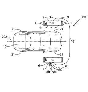
[0027] Figure 1 is a schematic diagram showing a top view of a system of
the
present invention comprising two electronically connected apparatuses for
determining
offset of wheels on the left and right sides of a moving vehicle;
[0028] Figure 1A is a schematic diagram showing a vehicle being driven
through
the system shown in Figure 1, at an angle relative to the system;
9
CA 02903886 2015-09-03
WO 2014/134719 PCT/CA2014/000228
[0029] Figure 2 is a schematic diagram showing a front view of
apparatus A
depicted in the system of Figure 1;
[0030] Figure 3 is a schematic diagram showing a back view of
apparatus B
depicted in the system of Figure 1;
[0031] Figure 4A is a schematic diagram of a top view of apparatus A
depicted in
the system of Figure 1 showing a beam from a laser displacement sensor
illuminating a
tire at a first location on the tire sidewall;
[0032] Figure 4B is a schematic diagram of a side view of the tire
depicted in
Figure 4A showing the first location on the sidewall of the tire;
[0033] Figure 4C is a schematic diagram of a top view of apparatus A
depicted in
the system of Figure 1 showing a beam from a laser displacement sensor
illuminating a
tire at a second location on the tire sidewall after the vehicle has moved
forward;
[0034] Figure 4D is a schematic diagram of a side view of the tire
depicted in
Figure 4C showing the second location on the sidewall of the tire;
[0035] Figures 5A and Figure 5B are schematic diagrams of wavy bumpy plates
to assist in suspension testing of vehicle wheels;
[0036] Figure 6A is a histogram of distance data collected on the
front left wheel
of an vehicle as the vehicle was driven forward past apparatus A as depicted
in Figure
1;
[0037] Figure 6B is a histogram of distance data collected on the front
right wheel
of an vehicle as the vehicle was driven forward past apparatus B as depicted
in Figure
1;
[0038] Figure 7A is a plan view of a vehicle with trauma to the rear
left wheel;
[0039] Figure 7B is a plan view illustrating the vehicle of Figure 7A
travelling; and
[0040] Figure 8 is a perspective view of one of the apparatuses shown in
Figure
1, with an additional sensor for use in determining camber of a vehicle wheel.
DESCRIPTION OF PREFERRED EMBODIMENTS
[0041] In this specification and in the claims, the use of the
article "a", "an", or
.. "the" in reference to an item is not intended to exclude the possibility of
including a
CA 02903886 2015-09-03
WO 2014/134719 PCT/CA2014/000228
plurality of the item in some embodiments. It will be apparent to one skilled
in the art in
at least some instances in this specification and the attached claims that it
would be
possible to include a plurality of the item in at least some embodiments.
[0042] It has been found that, while the measurement of static toe
(i.e. the
measurement of toe when the vehicle is stationary) can be useful, there are
several
problems with it as a tool to determine whether a particular wheel or tire
will incur undue
wear during use of the vehicle. In general, when static toe is measured, the
corners of
a polygon are determined, wherein the corners correspond to the centers of
each of the
four wheels of the vehicle. The angle of each wheel is then determined
relative to that
rectangle. Depending on the vehicle's suspension and other factors, the
orientation of
the wheels when the vehicle is stationary are not the same as the orientation
of the
wheels during operation of the vehicle. An example of a static toe measurement
is
shown in Figure 7A. The vehicle is shown at 10, and has a body 11 that is
represented
by a rectangle for simplicity. The vehicle 10 has four wheels shown at 21, and
shown
more particularly at 21FL (the front left wheel as viewed from a viewpoint
above the
vehicle 10), 21FR (the front right wheel), 21RL (the rear left wheel) and 21RR
(the rear
right wheel). As can be seen, there has been trauma to the vehicle's rear left
wheel
21RL, causing it to be out of alignment with the other three wheels. A static
toe
measurement would find that the front left, front right and rear right wheels
21FL, 21FR
and 21RR all have a toe of zero, and the rear left wheel 21RL has a toe value
of some
non-zero value. However, as can be seen in the view shown in Figure 7B, when
the
vehicle 10 is being driven, due to particular dynamics involved, the rear left
wheel 21RL
may drive the direction of movement of the vehicle 10 more than the rear right
wheel
21RR. The driver of the vehicle (not shown) may steer the vehicle 10 in an
effort to
compensate for the frictional forces that cause the right and left rear wheels
21RR and
21RL to urge the vehicle 10 in different directions. The resulting direction
of travel of
the vehicle 10 may be as shown in Figure 7B. As can be seen, when the dynamic
toe
measurements would be taken, the front and rear toe values would be zero, and
each of
the rear toe values would be about 1/2 of the static toe value of the rear
left wheel 21RL.
As can be seen, both the right and left rear wheels 21RR and 21RL have non-
zero tire
wear angles relative to the direction of travel of the vehicle 10. Such a
measurement
11
CA 02903886 2015-09-03
WO 2014/134719 PCT/CA2014/000228
would reveal that both the rear right and rear left wheels 21RR and 21RL have
non-zero
tire wearing angles and would thus incur wear.
[0043] Another issue relating to measurement of static toe is that,
depending on
how soft the vehicle's suspension is, and depending on whether there are any
problems
with suspension components, it may be possible to measure the static toe of
the vehicle
and to find that all the wheels have a suitable toe value, but to find that
the wheels
21 move depending on frictional and other forces that urge the wheels 10 to
take on
different toe values when the vehicle 10 is moving.
[0044] Figure 1 is a schematic diagram showing a top view of a system
200 that
10 is configured to determine the tire wearing angles of a vehicle in
accordance with an
embodiment of the present invention. The system 200 comprising two
electronically
connected optical displacement sensing apparatuses A,B of the present
invention for
determining an offset in wheels on the left and right sides of a vehicle 10
that is moving
forward past the apparatuses A,B in the direction of the arrow. Figure 2 is a
schematic
diagram showing a front view of apparatus A. Figure 3 is a schematic diagram
showing
a back view of apparatus B. Apparatuses A,B are identical and element
numbering in
Figures 1-3 applies equally to both.
[0045] Each apparatus A,B comprises tower 2 mounted on base 9 having
height
adjustable feet 1 at each corner of the base. Visible laser displacement
sensor 3 is
mounted fixedly in the tower and configured to emit a laser beam parallel to
the surface
on which the apparatus rests at a height that may be, for example, between
about 25%
and about 40% of the height of the vehicle wheel 21 and is preferably at a
height of
about one third of the height of the wheel 21. Displacement sensor 3 is used
to
determine distance to the vehicle's wheels 21 during operation of the
apparatus. Three
further laser displacement sensors 4 are mounted in a single row in the base
and
configured to emit laser beams parallel to the surface on which the apparatus
rests at a
height below the chassis of a typical vehicle. Further displacement sensors 4
are only
used to confirm that a vehicle wheel 21 is passing the apparatus A,B (as
opposed to
some part of the vehicle body) and to confirm when the wheel 21 has passed the
apparatus. Sensors 4 need not be laser displacement sensors and may operate on
any
other suitable principle. Sensors 4 may be referred to as wheel detection
sensors. The
12
CA 02903886 2015-09-03
WO 2014/134719 PCT/CA2014/000228
two apparatuses A,B are electronically connected through a cable 5 and one of
the
apparatuses, in this case apparatus B, is electronically connected to computer
8
through cable 7 from a data port 6. The computer 8 is loaded with software for
interpreting signals from all of the laser displacement sensors on both
apparatuses to
determine distances from the displacement sensors to the surfaces on which the
laser
beams impact. The software determines distances from each displacement sensor
3 to
the vehicle's wheel 21. Only data from displacement sensors 3 are used in
wheel
condition assessment.
[0046] The computer 8 includes processor 8a, a memory 8b, and an
output
device 8c, which may be, for example, a display. The computer 8 is but one
example of
a control system. The control system may include a single processor and a
single
memory, or could have multiple processors and multiple memories. In the event
of
having a plurality of processors and memory, the processors and memory may be
in a
single housing, or may be distributed between a plurality of housings.
[0047] The height of the laser displacement sensor in each apparatus may
optionally be adjusted by adjusting the height adjustable feet 1, to be at
about one-third
the diameter of the wheel 21 off the surface on which the wheel 21 is
traveling. The
height adjustable feet 1 may also be used to level the apparatus A,B on an
uneven
surface. The two apparatuses A,B may be positioned roughly across from each
other
and so that the beams from the laser displacement sensors 3 are roughly
perpendicular
to the direction of motion of the vehicle 10. Each apparatus A,B is an
independent unit
that is in no way attached to or mounted on the vehicle 10.
[0048] Figures 4A-4D depict a single apparatus (apparatus A) and
illustrate the
measurement of the offset for the front left wheel 21 of the vehicle 10.
Referring to
Figures 4B and 4D, the wheel 21 includes a rim and a tire, shown at 21a and
21b
respectively. In the event that a hubcap is provided, the hubcap may be
considered
part of the rim for the purposes of this description. In operation, the
apparatus A is
stationary while the vehicle 10 moves forward past it in the direction of the
arrow. As the
vehicle 10 passes the apparatus A, the laser displacement sensor 3 sends
signals back
to the computer 8 at a selected frequency (e.g. 200 distance measurement
signals per
second), and the computer 8 calculates the distance that beam 25 travels to
reach the
13
CA 02903886 2015-09-03
WO 2014/134719 PCT/CA2014/000228
vehicle 10. The computer 8 tracks and displays the distance data. The distance
data for
an example vehicle is shown in Tables 1 and 2, and is illustrated graphically
in the form
of histograms in Figures 6A and 6B.
[0049] The computer 8 determines the distances to two longitudinally
spaced
locations on the wheel 21, and determines the difference between the two
distances,
which is referred to as the offset, and which is indicative of the tire
wearing angle of the
wheel 21. Preferably, the two locations are on opposite sides of the
centerpoint of the
wheel. In other words, preferably, one location is on the leading half of the
wheel 21
and on is on the trailing half of the wheel 21. Preferably, the two locations
are on parts
of the wheel 21 that have the same lateral distance to the longitudinal
centerline of the
wheel, shown at CL in Figures 4A and 4B. The locations could be on the tire
sidewall
(shown at 21c) or the rim or the hub of the wheel. For ease of detection, the
locations
may be at points of maximum lateral bulge (shown at 30 and 31 respectively in
Figures
4B and 4D) for the tire 21b at whatever height the displacement sensor is
operating,
although other locations on the wheel 21 may be used. For example, the center
of the
tire sidewall 21c may also be a suitable location (the maximum lateral bulge
on a tire is
typically not at the center of the sidewall, but is instead closer to the
radially outer edge
of the tire 21b).
[0050] In the example shown in Figures 4A and 4B, as the vehicle wheel
21
passes the laser displacement sensor 3, beam 25 finds a point of maximum bulge
30 at
a first instant in time on the leading part of tire 21b on the tire's sidewall
about one-third
the way up off the surface. At this point, a first distance is established,
which is
displayed by the computer 8. Referring to Figure 40 and 4D, as the vehicle 10
continues to move forward, sometime later at a second instant in time, a
corresponding
maximum bulge point 31 on the trailing part of tire 21b on the tire's sidewall
passes by
the beam 25 about one-third the way up off the surface. At this point, a
second distance
is determined, which is displayed by the computer 8. The computer 8 calculates
the
difference between the first and second distances, which is referred to as the
offset.
The offset may be converted to a value for the tire wearing angle for the
wheel,
expressed as an angle using trigonometric relationships if the longitudinal
distance
between the first and second locations is known. The longitudinal distance
information
14
CA 02903886 2015-09-03
WO 2014/134719 PCT/CA2014/000228
may be inputted to the computer 8 prior to measuring the vehicle 10 based on
the tire
information provided on the sidewalls 21c of the tire 21. If the computer 8
determines
that the value for the tire wearing angle is greater than a selected value,
such as, for
example, about 1 degree, the computer 8 may indicate to a user that there may
be a
wheel alignment problem (e.g. via output device 8c). Thus, the control system
is
configured to a) receive output signals from however many of the apparatuses
A,B there
are and to b) output data based on a difference between the distances to the
two
locations 30 and 31 on the wheel 21 that were determined. Figures 4A-4D may
relate
to determining the offset and value for the tire wearing angle for a first
wheel 21 (e.g.
the left, or driver's side, front wheel). Data from the other apparatus at the
other side of
the vehicle (e.g. the right, or passenger side, front wheel) is factored into
the
determination as to whether the difference is due to the vehicle 10 not
tracking straight
(i.e. perpendicularly to the emitted beams) as the vehicle passed the
apparatuses A,B.
If a significant offset is still found to exist, a test for a suspension
problem may be
undertaken by backing the vehicle past the apparatuses as described above.
[0051] It will be noted that, if the direction of travel of the
vehicle 10 shown by
arrow 202 in Figures 1 and 1 a, is not perpendicular to the directions of
travel of the
beams 25 this will affect the offset that is determined for the wheels 21. In
the example
shown in Figure 1, the vehicle 10 is traveling perpendicular to the beams 25
and so no
compensation needs to be made for the direction of travel of the vehicle 10.
However,
in Figure la, the vehicle's direction of travel 202 is not perpendicular to
the beams 25.
As a result, an offset will be measured even if the vehicle's wheels 21 are
all perfectly
aligned with the direction of travel 202 of the vehicle 10. By having the two
apparatuses
A,B take their measurements independently, but substantially simultaneously
(although
not necessarily precisely simultaneously), on corresponding first and second
front
wheels on both sides of the vehicle 10 and first and second rear wheels on
both sides of
the vehicle 10, the control system 8 can determine the direction of travel of
the vehicle.
[0052] More specifically, the control system 8 can determine the
distance to the
center of each wheel (e.g. by taking the average of the measurements at the
points 30
and 31 on each wheel 21), and can then determine the offset between the
centers of
the front and rear wheels 21. For example, using the example shown in Figure
la, the
CA 02903886 2015-09-03
WO 2014/134719 PCT/CA2014/000228
Gontrol system 8 may determine that the distance to the front right wheel
center is 1.0
m, the distance to the front left wheel center is 1.6 m, the distance to the
rear right
wheel center is 1.1 m, and the distance to the rear left wheel center is 1.5
m. Using this
information, along with information regarding the front and rear tracks of the
vehicle and
information regarding the wheelbase of the vehicle, the control system 8 can
determine
the direction of travel of the vehicle 10 and can then use the determined
direction of
travel to compensate for the determined offsets and tire wearing angles for
the wheels
21. For example, if the front and rear tracks of the vehicle 10 are the same
and if the
vehicle 10 was traveling perpendicularly to the beams 25, then there would not
be any
offset in the distances to the front wheels 21 and the rear wheels 21.
However, using
the example data above, an offset of 0.1 m is apparent. This offset of 0.1 m,
when
combined with the wheelbase information can be used to determine the angle of
the
vehicle relative to the beams 25. For example, if the wheelbase of the vehicle
10 is 2.8
m, then the tangent of the angle of the direction of travel 202 of the vehicle
10 is 0.1 /
2.8 which equals 0.0357, which corresponds to an angle of 2.05 degrees
relative to a
hypothetical reference line that is perpendicular to the beams 25. This 2.05
degrees
can then be subtracted (or added, as appropriate) to the tire wearing angle
values
determined for the wheels 21 to arrive at the true tire wearing angles for the
wheels 21.
[0053] The effect of tracking on the second wheel will be the opposite
of that on
the first wheel so information from the two sides can be compared to determine
if there
is actually a misalignment problem or whether the effect is all due to wheel
tracking.
Because the measurements made on the two wheels are independent, there is no
need
to perfectly align the locations between the two wheels. However, for better
consistency
of data accumulation, it is preferred that the locations being measured on the
two
wheels are at least relatively closely aligned. Wheel tracking problems can
also arise
from differences in suspension or tire inflation between the two wheels. To
further
improve consistency of data and compensate for tracking issues, distance data
from
both sides of the vehicle may be averaged, multiple passes of the vehicle past
the fixed
point may be done to increase the amount of data, and calibration methods may
be
employed to compensate for uneven driving surfaces.
16
CA 02903886 2015-09-03
WO 2014/134719 PCT/CA2014/000228
[0054] Using two apparatuses A,B also permits a determination to be
made of the
wheelbase of the vehicle 10 on each side of the vehicle 10. This in turn
permits the
control system 8 to determine if the two determinations match each other. If
the control
system 8 determines that the determinations do not match it means that the
wheelbase
on one side of the vehicle 10 is not the same as the wheelbase on the other
side of the
vehicle 10, which can be an indication that the vehicle 10 incurred trauma. If
this is
found by the control system 8, the control system 8 can notify a user using
the output
device 8c.
[0055] Data collected on the front wheels of a 2012 Dodge Caravan
vehicle using
the system described in Figure 1 are shown in Table 1 and Figures 6A and 6B.
During
operation, the laser displacement sensors are operated continuously, and as
the vehicle
drives past the lasers data is collected at high frequency. In order to locate
which data
represent the passage of the wheels rather than the chassis or fender, and
then to
determine the appropriate data points from which the offset may be calculated,
an
algorithm was used to average data over 15 samples surrounding each sample
point
and then to calculate the variance for each sample. Inspection of the average
for a local
minimum associated with a low variance is an indication of the passage of a
wheel. The
data is shown on Table 1 for the front wheels. In Table 1, Local Mean is the
mean over
15 samples surrounding a sample point and Local Variance is the variance of
the
sample point from the mean. The Measurement, the Local Mean and the Local
Variance
for the appropriate data points for each wheel that may be used for offset
calculation are
shown in bold underline in the table. It is the value of the Measurement at
each of these
points that is used in the offset calculation.
[0056] The data were converted into histograms for easy visual
inspection. Figure
6A is the histogram for the front left wheel and Figure 6B for the front right
wheel. First,
it is immediately evident from the histograms that the region between about
Points 45
and 416 for the front left (see Figure 6A) represents the passage of the front
left wheel
and the region between about Points 30 and 404 for the front right (see Figure
6B)
represents the passage of the front right wheel. The tire profile can be
readily seen in
these histograms with a generalized minimum between two spikes in distance.
17
CA 02903886 2015-09-03
WO 2014/134719 PCT/CA2014/000228
[0057] For the front left wheel, with reference to Table 1 and Figure
6A, it can be
seen from the data and histogram that Point 118 forms a minimum distance at
the
leading part of the wheel. This is most readily seen by looking at the Local
Variance
surrounding this point. The Local Variances at Points 114-120 around Point 118
are
very small when compared to other points in the histogram, with the Local
Variance at
Point 118 being the smallest. Thus, Point 118 represents the point of maximum
bulge
on the sidewall of the leading part of the tire on the front left wheel. The
value of the
Measurement at Point 118 is 360.15 mm. This is the first location for the
offset
determination. A similar analysis from Table 1 and Figure 6A for the trailing
part of the
tire reveals that Point 358 is the point of maximum bulge on the sidewall of
the trailing
part of the tire on the front left wheel. The value of the Measurement at
Point 358 is
358.37 mm. Therefore, the offset for the front left wheel is 360.15 ¨ 358.37 =
1.78 mm,
which represents a slightly toe-in orientation for the wheel.
[0058] Similarly for the front right wheel, with reference to Table 1
and Figure 6B,
it can be seen from the data and histogram that Point 104 forms a minimum
distance of
379.65 mm at the leading part of the wheel, while Point 345 forms a minimum
distance
of 379.35 mm at the trailing part of the wheel. This represents an offset of
0.30 mm,
which represents a slightly toe-in orientation of the wheel.
[0059] The small offsets for both the left and right front wheels are
an indication
that the wheels are properly aligned.
Table 1 ¨ Front Wheels 2012 Dodge Caravan
Left Right
Point Measurement Local Mean Local Variance Measurement Local Mean Local
Variance
(mm) (15 points) (15 Points) (mm) (15 points)
(15 Points)
1 1599.98 1599.98
2 1599.98 1599.98
3 1599.98 1599.98
4 1599.98 1599.98
5 1599.98 1599.98
6 1599.98 1599.98
7 1599.98 1599.98
8 1599.98 1599.98
9 1599.98 1599.98 1599.98 1599.98
18
CA 02903886 2015-09-03
WO 2014/134719 PCT/CA2014/000228
. 10 1599.98 1599.98 1599.98 1599.98
11 1599.98 1599.98 1599.98 1599.98
12 1599.98 1599.98 1599.98 1599.98
13 1599.98 1599.98 1599.98 1599.98
14 1599.98 1599.98 1599.98 1599.98
15 1599.98 1599.98 1599.98 1599.98
16 1599.98 1599.98 1599.98 1599.98
17 1599.98 1599.98 0.00 1599.98 1599.98 0.00
18 1599.98 1599.98 0.00 1599.98 1599.98 0.00
19 1599.98 1599.98 0.00 1599.98 1599.98 0.00
20 1599.98 1599.98 0.00 1599.98 1526.31 86837.77
21 1599.98 1599.98 0.00 1599.98 1452.71 161943.24
22 1599.98 1599.98 0.00 1599.98 1379.80 224096.67
23 1599.98 1599.98 0.00 1599.98 1321.33 251319.34
24 1599.98 1599.98 0.00 1599.98 1263.20 270829.86
25 1599.98 1599.98 0.00 1599.98 1205.25 282935.89
26 1599.98 1599.98 0.00 1599.98 1147.68 287485.77
27 1599.98 1599.98 0.00 421.25 1090.27 284817.39
28 1599.98 1599.98 0.00 422.37 1033.13 274924.09
29 1599.98 1599.98 0.00 433.37 976.31 257871.05
30 1599.98 1599.98 0.00 664.60 919.60 233875.23
31 1599.98 1599.98 0.00 669.90 863.18 202913.69
32 1599.98 1524.66 90763.61 672.65 807.01 165106.33
33 1599.98 1449.35 169414.87 678.85 751.00 120549.83
34 1599.98 1374.04 235956.02 681.55 695.13 69303.64
35 1599.98 1298.70 290464.66 685.75 639.55 11441.68
36 1599.98 1223.36 332852.40 690.82 657.84
8275.59 ,
37 1599.98 1148.05 363090.12 692.62 676.27 4452.45
38 1599.98 1088.39 362521.47 697.30 694.18 303.86
39 394.90 1029.01 354132.08 701.17 697.82 286.24
40 394.98 969.99 337977.87 703.80 701.34 274.56
41 395.05 911.23 314248.97 706.17 704.91 259.98
42 394.50 852.76 283034.14 710.70 708.16 248.14
43 394.60 794.55 244458.87 713.82 711.39 232.08
44 395.02 736.61 198615.25 717.30 714.58 220.11
45 645.40 678.91 145609.21 719.92 717.65 215.49
46 649.87 621.49 85534.19 722.87 720.84 207.98
47 655.60 564.20 18459.20 726.15 723.83 200.73
48 659.82 582.52 17212.90 729.77 726.55 187.76
49 664.55 601.05 15293.38 730.80 729.39 178.71
50 668.57 619.74 12668.73 733.35 732.26 168.50
19
CA 02903886 2015-09-03
WO 2014/134719 PCT/CA2014/000228
. 51 673.02 638.62 9299.65 736.70 735.02 163.19
52 676.80 657.79 5199.45 740.00 737.68 156.04
53 681.12 677.08 339.57 743.67 740.18 147.64
54 683.40 680.83 311.20 745.10 742.69 139.88
55 688.05 684.50 284.49 744.75 745.23 135.80
56 691.50 687.95 262.04 749.15 727.96 5612.03
57 694.10 691.35 243.05 752.15 709.41 11047.94
58 696.57 694.64 227.84 754.77 690.22 16063.92
59 701.25 697.73 209.08 756.35 670.84 20288.40
60 703.65 700.76 196.08 757.42 650.71 23945.87
61 705.42 703.71 184.39 760.05 630.05 26837.94
62 708.65 706.52 175.42 763.55 608.93 28855.06
63 710.75 709.41 166.45 449.80 587.59 29945.02
64 714.25 712.09 159.43 432.92 566.35 30040.92
65 717.10 714.71 153.86 423.77 544.57 29135.19
66 718.12 717.26 145.80 423.32 522.59 27133.72
67 721.45 719.79 136.56 414.55 500.38 24024.98
68 723.95 704.49 4486.36 409.50 478.03 19811.52
69 726.12 687.30 9241.22 405.77 455.57 14497.12
70 729.62 669.67 13533.61 403.55 432.76 8005.06
71 731.00 651.05 17536.14 404.95 409.67 240.77
72 733.30 631.96 20935.83 400.77 406.20 136.43
73 734.90 612.13 23742.39 400.35 403.56 97.49
74 737.05 591.95 25739.77 399.42 401.45 77.77
75 456.47 571.46 26944.83 398.85 399.36 50.23
76 428.72 550.81 27157.28 397.92 397.72 40.03
77 423.32 529.61 26519.47 395.12 396.36 35.44
78 410.62 508.14 24893.24 394.22 395.17 34.28
79 405.30 486.37 22190.52 394.25 394.08 33.80
80 397.10 464.47 18434.35 390.67 392.78 30.57
81 ' 394.20 442.38 13573.40 390.00 391.71 30.77
82 390.17 420.13 7609.76 389.82 390.63 29.54
83 391.17 397.67 496.17 388.37 389.57 27.64
84 384.67 392.63 270.07 387.75 388.52 24.39
85 382.65 389.27 192.14 386.67 387.49 20.73
86 381.27 386.20 119.85 386.10 386.64 18.44
87 380.67 383.78 87.50 384.25 385.80 16.20
88 379.85 381.61 63.35 383.55 384.94 12.52
89 378.87 379.97 52.16 383.05 384.28 11.41
90 377.60 378.43 43.22 382.45 383.63 10.21
91 375.95 377.00 40.23 382.15 383.01 8.18
CA 02903886 2015-09-03
WO 2014/134719 PCT/CA2014/000228
92 374.90 375.54 30.17 381.42 382.48 6.61
93 374.25 374.30 30.73 381.55 381.99 4.95
94 371.90 373.18 30.80 380.70 381.57 3.59
95 370.50 372.14 30.08 380.50 381.16 2.32
96 370.87 371.09 28.63 380.12 380.87 1.75
97 369.67 370.04 26.75 379.65 380.62 1.31
98 367.22 369.03 24.03 379.90 380.41 0.93
99 367.85 368.07 21.26 379.90 380.23 0.66
100 364.75 367.19 18.85 379.90 380.07 0.42
101 364.77 366.33 16.49 379.90 379.95 0.30
102 364.70 365.51 13.41 379.50 379.83 0.12
103 363.87 364.80 11.76 379.60 379.76 0.07
104 362.95 364.18 10.36 379.65 379.74 0.04
105 362.72 363.53 7.86 379.64 379.79 0.14
106 362.20 362.96 5.64 379.62 379.92 0.35
107 361.87 362.53 4.68 379.56 380.08 0.77
108 361.20 362.05 2.90 379.50 380.30 1.44
109 361.10 361.76 2.56 379.70 380.56 2.30
110 360.60 361.48 2.03 379.55 380.88 3.48
111 360.62 361.19 1.37 380.15 381.30 5.02
112 360.45 360.97 0.90 381.00 381.77 6.91
113 360.42 360.81 0.63 381.65 382.29 8.92
114 360.35 360.65 0.39 382.52 382.89 11.29
115 360.22 360.53 0.23 383.37 , 383.57 13.90
116 360.20 360.42 0.10 384.07 384.33 16.66
117 360.20 360.36 0.06 385.00 385.16 , 19.10
118 360.15 360.33 0.03 386.15 386.07 21.76
119 360.32 360.38 0.10 387.20 387.09 24.15
120 360.32 360.47 0.29 388.02 387.76 21.41
121 360.20 360.63 0.66 389.25 388.35 18.50
122 360.20 360.84 1.27 390.45 388.90 15.45
123 360.22 361.10 2.08 391.75 389.41 12.68
124 360.12 361.44 3.32 392.75 389.88 10.16
125 360.70, 361.85 4.92 394.27 390.36 7.91
126 361.40 362.31 6.73 395.82 390.83 6.07
127 362.10 362.83 8.60 390.85 , 391.28 4.82
128 362.92 363.40 10.73 390.52 391.71 4.01
129 363.77 364.04 13.16 390.35 392.17 3.84
130 364.52 364.82 16.52 390.70 393.07 11.11
131 365.70 365.67 19.61 390.87 394.29 28.00
132 366.75 366.61 22.75 391.82 396.52 95.66
21
CA 02903886 2015-09-03
WO 2014/134719 PCT/CA2014/000228
133 367.62 367.53 23.58 392.50 398.91 168.08
134 368.40 368.13 20.63 393.37 401.07 221.30
135 369.42 368.70 17.64 394.00 403.09 263.48
136 370.65 369.24 14.70 395.52 405.41 289.43
137 372.70 369.74 11.96 403.60 408.02 315.15
138 373.72 370.17 9.44 409.92 411.10 351.19
139 375.20 370.56 7.17 427.47 414.26 373.39
140 374.85 370.84 5.52 431.05 417.64 387.51
141 370.40 371.06 4.37 428.82 420.41 357.65
142 370.50 371.22 3.60 428.00 422.78 306.41
143 370.77 371.32 3.16 428.10 424.89 245.25
144 ' 370.92 371.36 3.04 432.17 426.82 177.67
145 370.65 371.26 3.32 439.72 428.73 108.53
146 370.70 371.07 3.33 441.25 429.98 66.41
147 370.20 370.79 2.98 444.95 430.70 43.92
148 370.23 370.41 1.72 436.12 430.18 51.90 ,
149 370.25 370.10 0.32 430.42 429.35 61.26
150 370.00 370.13 0.35 427.10 428.61 70.91
151 369.95 370.15 0.37 424.87 427.89 80.32
152 369.15 370.15 0.38 426.05 427.15 88.58
153 369.62 370.10 0.34 423.73 426.14 94.24
154 369.32, 370.15 0.46 421.42 424.63 86.97
155 369.12 , 370.14 0.44 419.10 423.02 71.29
156 369.90 370.07 0.51 417.85 421.16 39.65
157 370.80 369.99 0.58 416.95 419.82 25.52
158 370.77 369.91 0.64 416.37 418.84 18.78
159 370.90 369.84 0.70 416.37 417.98 15.42
160 370.00 369.81 0.70 415.90 417.11 14.75
161 371.55 369.84 0.67 415.55 415.55 23.88
162 370.42 369.84 0.67 415.55 414.03 34.41
163 369.10 369.89 0.66 415.15 412.60 44.72
164 368.95 369.94 0.61 414.80 411.22 55.90
165 368.95 369.97 0.62 414.65 409.85 66.70
166 368.95 369.94 0.59 413.40 408.47 76.21
167 369.52 369.92 0.55 410.95 407.09 83.49
168 369.65 369.88 0.50 401.12 405.67 87.51
169 369.62 369.92 0.53 399.37 404.24 89.06
170 370.05 369.97 0.48 398.47 400.50 71.93
171 369.95 370.13 0.50 397.10 399.01 59.56
172 370.30 370.28 0.46 395.85 397.53 42.77
173 370.40 370.43 0.37 394.90 396.17 24.25
22
CA 02903886 2015-09-03
WO 2014/134719 PCT/CA2014/000228
, 174 370.40 370.57 0.40 394.25 394.97 7.84
175 370.30 370.73 0.46 393.72 394.42 5.13
176 370.60 370.91 0.53 393.00 393.99 3.35
177 370.70 371.07 0.60 393.47 393.64 1.84
178 - 371.25 371.22 0.60 392.40 393.37 0.92
179 371.25 371.35 0.60 392.45 393.19 0.45
180 371.25 371.50 0.63 392.50 393.08 0.23
181 371.17 371.66 0.61 393.02 392.98 0.13
182 371.65 371.81 0.53 393.00 392.96 0.11
183 372.00 371.96 0.48 392.85 392.97 _ 0.11
184 372.40 372.11 , 0.40 392.90 392.95 0.09
185 372.36 372.24 0.41 393.17 393.00 0.07
186 372.32 372.37 0.39 393.14 393.05 0.05
187 372.25 372.48 0.31 393.14 393.08 0.03
188 372.67 372.60 0.19 393.15 393.11 0.05
189 372.66 372.69 0.13 392.77 393.13 0.04
190 372.65 372.77 0.10 393.45 393.14 0.04
191 372.85 372.83 0.11 393.12 393.14 0.04
192 372.90 372.90 0.12 393.22 393.43 1.29
193 373.17 373.00 0.13 393.15 394.02 6.22
194 373.20 373.06 0.09 393.15 394.86 15.26
195 372.92, 373.11 0.10 392.90 395.89 27.30
196 373.02 373.19 0.10 393.57 397.10 41.27
197 373.02 373.26 0.10 393.20 398.43 57.44
198 373.14 373.33 0.11 393.06 399.97 75.47
199 373.25 373.37 0.10 392.92 401.62 92A3
200 373.52 373.47 0.21 397.47 403.20 100.99
201 373.72 374.54 16.70 402.05 404.75 103.65
202 373.15 376.76 82.85 405.77 406.29 100.13
203 373.55 379.17 151.11 408.55 407.75 92.34
204 373.72 381.63 209.37 410.97 409.23 79.06
205 373.79 384.13 257.73 413.42 410.69 60.42
206 373.85 386.54 288.65 416.22 412.14 36.78
207 373.50 388.64 295.96 417.97 413.22 20.32
208 374.70 390.68 293.27 416.75 414.02 10.77
209 389.22 392.85 282.48 416.40 414.71 5.72
210 406.20 395.35 272.71 416.00 414.62 7.03
211 409.27 397.74 247.61 415.50 414.72 6.40
212 409.90 400.11 210.19, 415.40 414.63 6.82
213 410.67 402.32 159.14 414.92 414.33 7.13
214 409.40 403.93 98.67 414.77 413.91 6.48
23
CA 02903886 2015-09-03
WO 2014/134719 PCT/CA2014/000228
, 215 404.92 405.32 40.63 413.57 413.55 6.23
216 404.37 405.70 29.62 414.10 413.19 6.01
217 405.75 404.90 38.33 416.17 412.86 5.63
218 411.00 , 403.90 43.89 407.20 412.54 5.37
219 409.57 402.82 47.51 412.47 412.23 4.90
220 ' 409.32 401.66 48.28 411.95 411.94 4.52
221 407.07 400.57 47.94 411.75 411.64 4.04
222 397.55 399.78 49.96 411.75 411.37 4.00
223 395.52 399.01 51.34 411.35 411.07 3.61
224 394.97 398.08 50.86 410.92 410.73 1.62
225 394.22 396.71 41.04 411.12 410.97 0.67
226 394.32 395.49 29.73 410.65 410.89 0.51
227 393.70 394.26 16.00 410.80 410.85 0.44
228 393.20 393.17 3.91 410.47 410.83 0.41
229 393.13 392.70 2.82 410.30 410.81 0.38
230 393.05 392.35 2.55 409.57 410.83 0.40
231 392.75 392.05 2.23 409.55 410.87 0.44
232 391.82 391.79 2.02 411.05 411.11 1.39
233 390.50 391.52 1.64 410.90 411.29 1.74
234 391.30 391.28 1.38 411.25 411.46 1.98
235 390.85 391.08 1.16 411.33, 411.70 2.33
236 390.70 390.92 0.85 411.40 411.98 2.65
237 390.50 390.76 0.50 411.52 412.33 2.68
238 390.25 390.60 0.20 411.56 412.73 2.75
239 390.40 390.53 0.09 411.60 413.20 4.35
240 390.35 390.53 0.09 414.65 413.91 8.37
241 390.32 390.52 0.08 413.47 414.83 15.71
242 390.15 390.53 0.09 413.30 415.66 19.90
243 390.15 390.62 0.22 414.05 416.44 21.86
244 390.67 390.76 0.51 414.45 416.00 29.40
245 390.62 391.02 1.18 414.82 415.49 38.17
246 390.40 391.20, 1.43, 415.67 414.96 46.63
247 390.80 391.41 1.72 418.07 414.23 55.19
248 390.50 391.63 1.96 421.52 413.56 62.97
249 391.15 391.90 2.17 424.97 412.92 69.41
250 391.05 392.19 2.37 423.85 412.27 74.23
251 391.95 392.50 2.81 423.05 411.63 77.39
252 392.70 392.85 3.22 404.92 411.07 78.32
253 394.02 393.22, 3.33 403.90 411.61 88.02
254 393.10 393.62 3.63 403.75 412.04 96.89
255 393.52 394.15 4.27 403.65 413.66 169.29
24
CA 02903886 2015-09-03
WO 2014/134719
PCT/CA2014/000228
. 256 393.72 394.37 3.59 403.45 415.03 230.55
257 394.12 394.48 2.98 403.75 413.63 233.55
-
258 . 394.57 394.35 3.96 404.25 411.59
254.74
259 395.35 393.97 7.47 404.85 410.77 276.47
-
260 395.85 393.25 15.12 406.35 409.98 297.47
261 395.95 392.33 28.12 423.77 409.20 316.99
262 396.75 391.11 47.38 424.60 408.43 _ 335.12
263 398.40 389.70 69.44 445.85 407.67 351.85
264 394.50 388.26 86.71 445.50 406.90 . 367.50
-
265 392.72 386.79 99.36 402.82 406.08 . 382.01
266 389.97 385.29 105.59 392.47 405.23 395.19
267 387.00 383.75 106.39 392.65 404.28 406.44
268 383.25 382.19 101.93 392.05 402.12 386.17
269 379.30_ 380.56 90.94 392.06 399.94 352.54
I--
270 375.20 378.82 69.93 392.07 396.32 192.89
271 - 372.52 377.34 53.08 392.07 392.71
7.95
272 372.60 375.97 36.02 392.07 392.01 - 0.13
273 372.47 374.79 21.51 392.06 391.99 0.12
274 372.85 373.84 10.20 392.05 391.98 0.11
275 372.70 373.13 3.44 392.10 392.06 0.19
276 372.67 372.87 1.02 391.40 392.13 0.28
277 372.30 372.45 1.51 391.82 392.23 0.42
278 372.22 372.30 1.86 391.62 392.36, 0.64
279 372.26 372.23 1.88 391.30 392.52 0.89
280 372.26 _ 372.13 1.98 392.40 392.68 1.13
281 372.25 372.01 2.01 _ 392.20 392.86 1.38
282 372.70 371.88 2.08 392.50 393.06 1.66
283 372.62 371.77 2.08 393.12 , 393.31 1.70
284 375.40 371.69 2.08 393.17 393.57 , 1.89
285 369.00 _ 371.58 2.14 393.60 393.89 2.07
286 370.17 371.45 2.19 394.05 394.23 1.91
287 371.60 371.32 2.22 394.37 394.52 2.05
288 370.95 371.19 2.21 394.52 394.84 , 2.00
289 371.10 371.03 2.08 394.77 395.15 1.87
290 370.70 370.87 1.92 395.10 395.44 1.86
291 371.00 370.49 0.41 395.15 395.73 1.71
292 371.10 370.54 0.29 395.75 396.00 1.57
293 370.55, 370.51 0.32 396.37 396.24 1.43
294 370.42 370.36 0.31 396.37 396.46 1.28
295 370.30 370.26 0.34 396.80 396.66 1.04
296 370.30 370.10 0.43 397.02 396.84 0.81
CA 02903886 2015-09-03
WO 2014/134719 PCT/CA2014/000228
. 297 370.28 369.96 0.54 397.10 396.98 0.58
298 ' 370.25 369.80 0.58 397.45 397.10 0.32
299 369.65 369.65 0.50 397.50 397.14 0.23
300 369.70 369.60 0.45 397.65 397.13 0.25
301 369.80 369.55 0.40 397.65 397.06 0.43
302 369.32 369.62 0.58 397.65 396.91 0.84
303 369.45 369.86 1.82 397.50 396.69 1.55
304 368.70 370.17 3.54 397.52 396.43 2.32
305 368.63 370.55 5.74 397.17 396.12 3.07
306 368.55 371.16 10.06 396.95 395.75 4.07
307 368.80 371.98 17.66 396.40 395.29 5.29
308 369.87 373.02 29.06 396.20 394.71 7.48
309 369.70 374.33 44.36 395.35 394.06 9.72
310 371.32 375.85 62.93 394.57 393.55 9.83
311 373.95 377.69 85.73 393.65 393.04 9.43
312 374.94 379.59 102.91 393.24 392.57 8.59
313 375.92 381.37 108.24 392.82 392.12 7.37
314 378.72 382.94 103.10 391.87 391.72 6.10
315 382.05 384.29 92.54 390.87 391.36 4.59
316 385.42 385.45 76.48 388.87 391.06 3.38
317 388.95 386.34 61.41 387.90 390.79 2.44
318 392.17 386.93 50.95 389.90 390.57 1.82
319 396.37, 387.34 43.01 389.80 390.74 3.31
320 397.10 387.50 39.51 390.10 390.83 3.79
321 395.20 387.32 43.30 390.30 390.85 3.86
322 392.47 386.80 53.19 390.42 390.85 3.86
323 390.02 385.96 66.30 390.75 390.89 3.72
324 387.17 384.83 78.17 390.87 390.89 , 3.69
325 384.67 383.41 86.12 390.50 390.68 4.81
326 382.82 381.66 83.40 390.30 390.38 6.73
327 381.00 379.82 73.23 395.90 389.99 9.24
328 378.30 378.10 61.06 394.07 389.52 12.25
329 376.07 376.53 49.63 392.27 388.97 15.68
330 374.27 375.19 37.83 390.80 388.34 19.37
331 372.80 374.34 26.85 389.45 387.64 22.83
332 372.02 373.53 18.77 387.97 386.90 26.46
333 370.85 372.70 12.54 386.72 386.19 28.93
334 370.15 371.93 7.76 385.30 385.10 24.11
335 369.55 371.26 5.34 384.25 384.13 19.58
336 369.30 370.60 5.09 383.25 383.28 15.58
337 368.97 369.99 5.87 382.22 382.51 12.01
26
CA 02903886 2015-09-03
WO 2014/134719 PCT/CA2014/000228
. 338 369.92 369.44 7.16 381.17 381.84 8.78
339 374.42 368.86 8.96 380.45 381.26 6.24
-340 372.47 368.29 11.42 379.45 380.76 4.12
341 370.47 367.70 14.27 379.57 380.37 2.62
342 369.42 367.07 17.68 379.50 380.06 1.48
343 368.27 366.42 20.91 379.51 379.81 0.70
344 366.15 365.72 24.46 379.52 379.66 0.27 _
345 365.12 364.95 26.40 379.35 379.60 0.12
346 364.47 363.88 21.96 379.42 379.61 0.14
347 363.37 362.93 17.97 379.15 379.73 0.32
348 362.27 362.12 14.73 379.30 379.89 0.64
349 361.32 361.38 11.33 379.40 380.07 0.98
350 360.15 360.72 8.13 379.60 380.32 1.62
351 359.55 360.20 6.13 379.55 380.61 2.42
352 358.45 359.75 4.43 379.95 380.99 3.59
353 358.40 359.35 2.79 380.25 381.45 5.20
354 358.25 359.03 1.57 380.60 382.02 7.26
355 358.28 358.78 0.77 381.25 382.66 9.67
356 358.30 358.60 0.28 381.95 383.34 11.76
357 358.40 358.54 0.13 382.20 384.03 13.42
358 358.37 358.50 0.07 383.25 384.98 17.92
359 358.36 358.58 0.15 383.95 385.91 20.86
360 358.35 358.73 0.45 385.10 386.97 24.72
361 358.45 358.88 0.63 386.30 388.03 27.11
362 358.55 359.12 1.16 387.70 389.14 29.47
363 358.58 359.42 2.02 388.90 390.37 33.32
364 358.60 359.76 3.04 389.50 391.65 35.34
365 359.20 360.15 4.12 390.00 392.94 37.23
366 358.95 360.59 5.29 393.87 394.35 39.73
367 359.60 361.18 7.79 393.90 395.95 46.52
368 360.72 361.84 10.42 396.05 397.81 59.89
369 360.50 362.54 12.85 396.50 399.93 81.30
370 361.82 363.44 17.32 397.90 402.58 124.22
371 362.87 364.37, 20.61 400.47 406.20 219.06
372 363.55 365.36 24.31 401.30 410.49 346.37
373 364.15 366.44 26.98 402.70 437.21 10106.87
374 364.90 367.55 29.20 405.00 463.76 18218.73
375 367.32 368.75 33.32 409.15 489.94 24701.75
376 368.30 369.98 34.30 414.17 515.95 29640.19
377 369.07 371.29 37.13 419.47 541.85 33150.41
378 372.05 372.77 43.20 428.70 567.49 35241.41
27
CA 02903886 2015-09-03
WO 2014/134719 PCT/CA2014/000228
, 379 372.52 375.11 79.45 443.75 592.92 35885.63
380 374.02 377.47 107.23 454.37 617.93 35075.40
381 375.15 379.82 126.78 794.72 642.61 32949.33
382 376.25 382.72 175.27 792.20 666.88 , 29644.13
383 378.77 386.56 277.82 788.77 690.68 25252.83
384 378.97 401.48 3057.55 786.62 713.93 19848.29
385 381.47 427.33 11451.81 786.40 736.29 13681.64
386 385.02 453.09 18383.57 785.00 757.44 7133.20
387 398.75 478.60 23818.51 782.75 777.68 133.51
388 399.45 503.84 27780.10 777.92 775.07 140.30
389 ' 400.15 528.82 30310.50 775.12 772.38 150.25
390 410.82 553.41 31473.51 773.25 769.59 168.92
391 425.90 577.87 31306.11 771.20 766.70 188.80
392 592.86 601.97 29875.20 768.12 763.66 199.18
392 ' 759.82 625.64 27275.29 764.15 760.38 210.37
394 759.00 648.23 23946.50 761.05 756.90 225.40
395 756.57 670.50 19513.99 757.92 753.46 247.62
396 753.77 692.67 14043.16 755.60 749.84 276.18
397 750.95 713.81 7979.00 751.80 745.90 311.86
398 747.60 733.78 1640.50 746.95 732.47 2287.94
_....
399 745.92 742.35 154.53 743.25 709.07 8710.35
400 ' 742.95 739.51 169.16 740.77 685.91 14022.79
401 740.07 736.54 177.35 735.85 662.95 18234.57
402 737.57 733.37 191.65 730.50 640.20 21370.56
403 733.52 730.18 205.04 726.40 617.60
23442.45 ,
404 732.70 726.88 , 221.51 720.82 595.26 24505.47
405 727.95 723.40, 248.66 714.05 573.20 24632.74
406 725.47 719.70 275.75 569.80 551.39 23820.49
407 721.32 715.83 307.33 417.20 529.72,
22069.86,
408 717.22 711.77 343.55 416.75 508.38
19475.53 .
409 714.47 707.36, 391.72 416.62 487.39 16092.93
410 709.12 702.69 456.88 416.60 466.68 11919.92
411 705.87 679.85 6814.29 416.63 446.35 7048.48
_ ._..
412 701.45 657.30 12118.59 416.65 426.48 1572.26
413 695.40 634.87 16385.59 416.12 416.22 0.23,
414 690.35 612.74 19632.73 416.10 416.13 0.16
415 684.95 590.89 21901.99 415.75 416.06 0.14
416 679.20 569.23 23202.66 415.70 416.00 0.13
417 671.37 547.88 23640.10 415.71 415.95 0.10
418 663.50 526.74 23185.94 415.72 415.91 0.07
419 390.07 505.90 21900.34 415.80 415.88 0.03
28
CA 02903886 2015-09-03
WO 2014/134719 PCT/CA2014/000228
-, 420 389.67 485.46 19867.04 416.02 415.86 0.02
421 389.10 465.36 17102.19 416.00 415.87 0.03
422 389.35 445.60 13660.88 415.77 415.90 0.03
423 389.48 426.18 9596.35 415.74 , 415.92 0.03
424 389.60 407.31 5023.09 415.70 415.95 0.03
425 388.87 388.97 0.33 415.87 415.95 0.03
426 388.81 388.87 0.25 416.05 415.96 0.03
427 388.75 388.78 0.21 416.12 415.96 0.03
428 388.80 388.73 0.21 415.92 415.92 0.04
429 388.85 388.67, 0.19 416.25 415.88 0.08
430 388.55 388.60 0.14 416.12 415.83 0.14
431 387.97 388.55 0.07 416.05 415.80 0.16
432 388.35 388.57 0.10 416.05 415.76 0.18
433 388.30 388.61 0.14 415.82 415.70 0.19
434 388.57 388.65 0.18 415.85 415.62 0.21
435 388.37 388.69 0.21 416.05 415.56 0.23
436 388.37 388.72 0.24 415.47 415.48 0.21
437 388.42 388.78 0.27 415.15 415.40 0.19
438 388.40 388.87 0.23 414.97 415.33 0.17
439 388.80 415.25
440 389.30 415.24
441 389.36 415.22
442 389.37 414.95
443 389.37 415.00
444 389.37 415.00
445 389.37 415.00
446 389.37 415.00
[0060] One test that can be undertaken after carrying out a test to
determine the
value for the tire wearing angle for the wheels of the vehicle 10 is a test to
determine if
any play is present in the suspension system of the vehicle 10. The ability to
assess
other wheel conditions besides alignment is advantageous. Play in wheel
suspension
can cause a wheel to be angled in or out depending on whether the vehicle is
moving
forward or backward. To determine if there is play in the wheel suspension,
the vehicle
is driven forward and the two distance measurements made. Then the vehicle is
10 driven backward and the two distance measurements are made. Alternatively,
the
29
CA 02903886 2015-09-03
WO 2014/134719 PCT/CA2014/000228
vehicle may be driven backwards first and then forwards. When moving backward,
the
first and second locations on the wheel are the same as the second and first
locations
when the vehicle is moving forward. If there is no play in the suspension, the
sign of the
offset between forward and backward motion of the vehicle should change (i.e.
from
positive to negative or from negative to positive). For example, in one of the
examples
above, a value of 379.65 mm was found at the leading part of the wheel, and a
value of
379.35 mm was found at the trailing part of the wheel when the vehicle was
driven
forward, for an offset of 0.30 mm. When driven backwards, if the wheels remain
oriented exactly the same way a leading part value of 379.35 mm and a trailing
part
value of 379.65 mm will be obtained, providing an offset of -0.30 mm. If,
however, there
was play in the suspension, and the wheel shifted as a result of friction when
being
driven backwards, the values may be 379.35 (leading) and 379.65 (trailing) due
to the
shift in the orientation of the wheel, resulting in an offset of 0.30 mm
again. Thus, if a
change in the sign of the offset direction is not seen (i.e. if the sign of
the offset remains
the same), then there may be a suspension problem in one or both wheels being
measured. Since, as discussed previously, wheel tracking problems may be
caused by
suspension play and the offset is also dependent on wheel tracking, such
suspension
information can be collected even when the wheels themselves are aligned
properly.
However, a more thorough inspection would be needed to determine whether the
issue
is a suspension issue or some other issue (e.g. relating, for example, to tire
inflation).
[0061] With reference to Figure 8, in some embodiments two
displacement
sensors may be provided on each apparatus A,B (apparatus A is shown in Figure
8),
wherein the two displacement sensors 3a and 3b are vertically aligned but
spaced apart
along the same vertical axis (shown at Av). For example, one at, for example,
about
one-third of the height of the wheel and another at, for example, about two-
thirds of the
height of the wheel, which permits the computer to measure wheel camber. More
generally, providing two displacement sensors that are vertically aligned but
spaced
apart along the same vertical axis, and in particular two sensors that are
positioned at
symmetrical vertical distances above and below the center of the wheel 21,
permits a
determination of the camber of the wheel 21 using the offset between the two
different
distance measurements.
CA 02903886 2015-09-03
WO 2014/134719 PCT/CA2014/000228
[0062] Figures 5A and 5B depict two suspension testing plates 38a,38b
to assist
in testing for play in the suspension components holding the vehicle wheels.
The
following description of the testing plates is with reference to Figure 5A,
but the one
depicted in Figure 5B has corresponding features discussed in relation to
Figure 5A.
The suspension testing plates may include working surface 39 that have
undulations 41
thereon. The undulations 41 include at least a first undulation 41a that
slants downward
laterally towards one side of the plate 38a and a second undulation 41b that
slants
downward laterally towards the other side of the plate 38a. By providing
successive first
and second undulations that slant towards opposite sides, any play in the
wheel of the
vehicle would cause the vehicle wheel to turn in when traveling over one of
the
undulations 41, and to turn out when travelling over the other of the
undulations 41. By
measuring the alignment of the wheel as it travels over both undulations 41a
and 41b, it
can be determined whether the alignment of the wheel changes from one
undulation to
the other, which would be indicative of play in the suspension elements
holding the
wheel.
[0063] As a vehicle 10 travels the weight of the vehicle 10 bears
upon the
suspension elements and through them, the wheels. Over time, even if there is
play in
the suspension elements, the weight of the vehicle may cause the joints where
the play
exists to seize to some degree. As a result, the play that exists in the
suspension
system is hidden in some situations even though it exists. To eliminate any
effect from
seizure of any joints, the plate 38a may further include bumps 40, which are
provided so
as to induce small, sharp movements in the wheel as the wheel travels over
them. Such
bumps 40 may be spaced relatively far apart such that each bump is
individually
configured to loosen any seized joints. Alternatively, the bumps may be spaced
relatively close together so as to induce a vibration in the wheel as the
wheel passes
over them in an effort to loosen any seized suspension joints.
[0064] In the embodiment shown, the bumps 40 may be formed along the
mating
edges of successive generally triangular surfaces 42 that extend out of plane
from one
another by a selected angle.
[0065] If there were no suspension play at the vehicle wheel, the wheel
would
remain upright as it passes over the undulations 41 and so there would be no
change in
31
CA 02903886 2015-09-03
WO 2014/134719 PCT/CA2014/000228
the distances measured to the points on the wheel. In other words, its degree
of
alignment would remain constant as it passed over the undulations 41. If
however, there
is play in the suspension, then the orientation of the wheel will change as
the wheel
passes over the undulations 41 and is subject to the changing forces from
successive
undulations that urge the wheel in different directions. As a result,
measurements of the
wheel's alignment would change from one undulation to the next.
[0066] The novel features of the present invention will become
apparent to those
of skill in the art upon examination of the detailed description of the
invention. It should
be understood, however, that the scope of the claims should not be limited by
the
preferred embodiments set forth in the examples, but should be given the
broadest
interpretation consistent with the specification as a whole.
32