Note: Descriptions are shown in the official language in which they were submitted.
DUAL AXIS ROTOR
RELATED APPLICATIONS
This application claims priority benefit of U.S. Serial Number 13/840,514,
filed March 15, 2013,
BACKGROUND OF THE DISCLOSURE
Field of the Disclosure
This disclosure relates to the field of fluid transfer devices having a
plurality of cooperating surfaces, one surface on a fixed stator and the other
surface on a nutating rotor.
CA 2903906 2019-07-23
CA 02903906 2015-09-03
WO 2014/139036
PCT/CA2014/050287
2
SUMMARY OF THE DISCLOSURE
Disclosed herein is a fluid flow apparatus comprising in one example: a
housing having a frusta-spherical inner surface; wherein the housing is fixed
in
space; a stator having a center axis, and a front face comprising lobes and
valleys; the stator fixed to the housing; a rotor having an axis, and a frusta-
spherical radially outward surface; wherein the rotor nutates about the
stator. The
term "frusta" comes from the Latin word "frustum" meaning "a piece broken
off".
A frusta-spherical surface therefore is a surface forming a part of a sphere.
In
one example a static seal is provided between the frusta-spherical outward
surface of the stator and the inner frusta-spherical surface of the housing.
The
apparatus may be arranged wherein the axis of the stator intersects the axis
of
the rotor; wherein the axis of the stator is offset from the axis of the rotor
by an
alpha (a) angle. In one example, the rotor having a front face with lobes and
valleys is configured to interoperate with the lobes and valleys of the
stator. In
one example, the number of lobes on the rotor are equal to the number of lobes
on the stator such that net rotation of the rotor relative to the stator is
not
permitted. In one example, the device is arranged wherein the lobes and
valleys
of the stator are substantially in fluid tight seal to the lobes and valleys
of the
rotor at least at two points during rotation/precession of the rotor. Also
disclosed
is a gearing system utilizing a housing ring gear fixed to the housing; a
planet
gear carrier nutating with a rotor; a plurality of planet gears rotating about
an axis
fixed to the planet gear carrier and indexed off of the housing ring gear; a
rotor
ring gear attached to the rotor; wherein the planet gears index the rotor ring
gear;
and wherein the planet gears indexes the rotor relative to the stator.
The fluid flow apparatus may further comprise: an upper planet gear in a
plane with the rotor; indexed off of the housing ring gear; and indexing the
planet
gears.
The fluid flow apparatus as above may further comprise: a double gear in
a plane with the rotor; indexed off of the housing ring gear via a bevel gear
portion; and indexing the planet gears via spur gear portion. The double gear
CA 02903906 2015-09-03
WO 2014/139036
PCT/CA2014/050287
3
may be a unitary homogenous structure with a bevel gear portion and a spur
gear portion.
One significant advantage of the lobe/valley face designs disclosed herein
is the ability to produce a device wherein the surfaces of the pumping
chambers
are used to prohibit rotation of the rotor relative to the stator. Among
others, US
patent 3,895,610 discloses a nutating apparatus wherein two segmental sections
of a spherical body are rotated one relative to the other to compress a fluid.
In
this patent as with many of the prior art references known, gearing is
required to
provide the rotor with the necessary motion to follow the sinuous
configuration of
the stator. One significant advantage of the disclosed lobe/valley face
designs
disclosed herein is the ability to produce a device wherein the surfaces of
the
pumping chambers are utilized to prohibit rotation of the rotor relative to
the
stator. The working chamber remains at the same position relative to the
stator
while the chamber volume increases and decreases in a sinusoidal manner with
every nutation cycle. In many examples this eliminates the need for timing
gears
in the apparatus. Prior art devices require the rotor to move in precession
relative
to the stator to manifest the volume change.
The fluid flow apparatus as disclosed herein may be arranged wherein the
alpha (a) angle is between three (3) and forty-five (45) degrees, or in a
narrower
range, between 25 and 35 degrees. In some applications, an alpha angle of
thirty
(30) degrees has been found beneficial.
The fluid flow apparatus as recited herein may be arranged wherein each
of the stator and the rotor comprise an even number of lobes.
The fluid flow apparatus may be arranged wherein the lobes of each of the
stator and second rotor comprise a leading surface comprising substantially a
radial projection of a spherical involute. Alternatively, the lobes of each of
the
stator and second rotor comprise a leading (axial) surface comprising
substantially a spiral spherical projection of a spherical involute.
The fluid flow apparatus may be arranged wherein the lobes of each of the
first rotor and second rotor comprise a following (axial) surface comprising a
radial projection of a teardrop curve.
4
The fluid flow apparatus as recited herein may be arranged wherein the
second rotor is rotateably attached to a shaft passing through the housing and
transferring rotational torque with the second rotor.
The fluid flow apparatus as recited herein may be arranged wherein the
shaft passes through and rotates relative to the first rotor.
The fluid flow apparatus as disclosed herein may be arranged wherein the
shaft comprises: a first portion adjacent to the first rotor and coaxial
thereto; a
second portion adjacent to the second rotor and coaxial thereto; and wherein
the
first portion forms an angle relative to the second portion equal to the alpha
(a)
angle.
The fluid flow apparatus as recited above may further comprise: a main
shaft passing through the housing and rotating relative thereto; a precession
cam (eccentric rotor) fixed to the shaft so as to rotate there with; a
precession
shaft attached to the precession rotor so as to rotate about the main shaft at
a
precession angle thereto; wherein the precession shaft is attached to the
second
rotor coaxial with the axis of the second rotor; and wherein the precession
shaft
transfers rotational torque with the second rotor.
The fluid flow apparatus as recited herein may be arranged wherein the
precession angle equals the alpha (a) angle.
The fluid flow apparatus may be arranged wherein the precession cam
and precession shaft are counterbalanced.
The fluid flow apparatus may further comprise an indexer such as those
described in published and publicly available US Patent 8,602,758 issued
December 10,
2013 which may be referred to for further details as a description of
underlying
technology. In another example, the nutating rotor may be indexed using a gear
arrangement so as to maintain a predetermined gap, precision fit, or
interference fit
between said faces to provide sealing. In one example, the gear arrangement
may be
epicyclic, planetary, or a combination thereof.
The fluid flow apparatus as recited herein may be arranged wherein the
housing comprises: a first portion and a second portion fixedly attached to
the
first portion; wherein each of the first and the second portions each comprise
an
CA 2903906 2019-07-23
CA 02903906 2015-09-03
WO 2014/139036
PCT/CA2014/050287
inner surface forming the frusta-spherical inner surface of the housing; and
wherein the first portion and second portion meet at the equator of the frusta-
spherical inner surface.
The fluid flow apparatus as recited herein may further comprise: surfaces
5 defining inlet ports through the housing; surfaces defining outlet ports
through the
housing; wherein precession of the second rotor relative to the first rotors
forms a
region of maximum volume and a region of minimum volume between the first
and second rotors; and wherein the inlet ports and outlet ports are in fluid
communication with each of the valleys of the first and/or second rotor.
The fluid flow apparatus may be arranged wherein the inlet ports and
outlet ports comprise check valves providing one-way flow of fluid though
specific
regions of the apparatus.
The fluid flow apparatus may be arranged wherein the inlet ports and/or
outlet ports exit the housing substantially parallel to the shaft.
The fluid flow apparatus may be arranged wherein the inlet ports are
angled to direct a fluid flow to non-contacting portions of the lobes and/or
valleys
to remove precipitating debris therefrom.
The fluid flow apparatus as disclosed herein may be arranged wherein the
shaft comprises a surface defining a fluid conduit for passage of fluid for
cooling
and/or lubricant fluid to the second rotor. In one form, this is accomplished
by a
surface defining a longitudinal void through a substantial length of the
shaft.
The fluid flow apparatus as recited herein may further comprise turbulence
generating surfaces on non-inter contacting portions of the lobes of the first
and/or second rotors.
The fluid flow apparatus may further comprise a rolling seal on the non-
axial face of each lobe.
The fluid flow apparatus may further comprise a sliding seal on the axial
faces of each lobe for self cleaning.
A nutating positive displacement device is disclosed herein, in one form
comprising: a (stationary) stator and a (moving/nutating) rotor with equal
number
of mounds and valleys as the stator. In one form, the rotor follows a
precessing
6
motion with respect to the stator such that the central axis of the rotor is
at a
constant angle to the axis of the stator, and the rotor's axis rotates about
the
stator axis. The contoured seal faces of the mounds and valleys of the stator
and
rotor may be formed in such a way as to provide a predetermined gap, precision
fit, or interference fit between said faces to provide sealing.
The device recited above may be arranged wherein the constant angle of
precession (alpha (a) angle) and smooth motion of the rotor are determined by
a
series of bearings, one or more bearings of which are mounted at an angle on a
rotatable part, the rotatable part rotating about an axis that is parallel or
collinear
to the axis of the stator.
The device may be arranged wherein the stator and rotor are generally
spherical in their radially outward extremities and housed or partially housed
within an outer shroud assembly that has a spherically concave inner surface
to
engage the spherical outer surfaces of the stator and rotor with or without a
prescribed gap between said surfaces. In one form the shroud member is
stationary with respect to the stator and may provide a static seal between
the
shroud and stator.
The device may be arranged wherein the stator and rotor are generally
spherical in extremities and housed or partially housed within an outer shroud
assembly that has a spherically concave inner surface that is to engage the
spherical outer surfaces of the stator and rotor with or without a prescribed
gap
between said surfaces, the shroud member being fixed with respect to the rotor
and providing a static seal between the shroud and rotor component, and the
shroud moves in a precessing motion along with the rotor.
The devices may be arranged wherein the mounds and valleys are
comprised of a geometry such as that described in US Patent 6,634,873 which
may be reviewed for further details as a description of underlying technology,
spherical involutes, or a combination thereof such that one side of a mound
may
be comprised of a curve disclosed in the '873 patent and the other side may
comprise a spherical involute and adjoining surfaces therebetween.
CA 2903906 2019-07-23
,
7
The device may be arranged wherein the spherical involutes provide a
gap, precision fit, or interference fit for sealing.
The device may be arranged wherein the spherical involutes also provide
seal surfaces to transfer force from the rotor to the stator.
The device may be arranged wherein the lobes of the stator and rotor are
designed as balanced (by the methods described in US Patent 6,497,564 which
may be reviewed for further details as a description of underlying technology)
wherein undercuts are created so that the net torque due to fluid pressure
around
all of the lobes of the rotor is balanced, or rather, the net torque is made
effectively equal to zero by carefully designed cuts in the mounds and
valleys.
The device may be arranged wherein the mounds of the lobes have
apexes that are long and relatively thin and may become positively activated
by
pressure and deflect due to pressure causing the apexes to touch-down on the
opposing mound or valley forming a contacting seal.
The device may further comprise movable apex seals that are either
spring loaded or pressure activated and positioned at the apex or near the
apexes of the rotor and/or stator lobes.
The devices above may be arranged where the apexes of the mounds
are:
- constant radius along their length and form a portion of a cylinder or
- conical or
- portion of the apexes are flat or nearly flat such that when a rotor lobe
apex is at its maximum distance away from the stator during a
precession, the flat sides of the lobes of the rotor and stator form a gap
seal such that an escaping fluid would need to traverse a relatively long
gap length in order to leak thus forming something much like a labyrinth
seal at this position, or
- mound apexes that incorporate a cross sectional shape similar to that
shown in patent US Patent 7,837,451 B2 Figure 9, the edge meant to
reduce leakage by a labyrinth effect and may be incorporated on either
rounded apexes or flat apexes of mounds.
CA 2903906 2019-07-23
8
The device disclosed above may be arranged wherein the rotor and stator
mounds and valleys are formed of the same surface shapes. These shapes may
be circumferentially symmetric.
The devices above may be arranged wherein the rotor has mounds of a
different (circumferential) width than the mounds of the stator.
The devices disclosed above may be arranged wherein the mounds and
valleys are produced as illustrated in US Patent 8,602,758, December 10, 2013
apparatus disclosed in Figure 12 of that disclosure may be exemplary for this
application, whereby the apexes extend sideways. Alternatively, the
mound/valley
shapes shown in US Patent 6,923,055 (which may be reviewed as a description
of underlying technology) Figures 6A/6C item "D", and
Figure 9 item 50, are termed a "rabbit ear" design. This particular teardrop
lobe
shape is created by a process wherein, this rabbit ear (or "cutter") is a cone
or
cylinder or oval (or other shape) that is aligned tangent to the teardrop
shape of
the lobe such that it appears to extend like ears on a rabbit (where the axial
direction corresponds to the up/down direction of a rabbit standing up with
his ears up).
In US Patent 8,602,758 issued December 10, 2013, Figure 12 the cutters are
attached
no longer on teardrop base curves but instead are attached to ovals, and the
result is that-tie tangent of the oval is 90 degrees rotated from the tangent
of a
teardrop base curve. The result is the cutters are attached "sideways" ¨ the
rotor
tips cantilever sideways it the rotor is viewed end-on. Alternatively, rotors
and
stators with the mound and valley shapes disclosed in US Patent 3,101,700 may
be utilized.
Devices described above may incorporate, for example, indexers
illustrated in US Patent 8,602,758 such as the rollers within oval tracks,
ball bearings in
oval tracks, lenticular gears, other forms of constant velocity fixed angle
joint, or an
indexer such as the Spherical Involute Gear Coupling (US 2012/0285282 November
15,
2012) or other timing gear system such as bevel gears, spiral bevel gears,
Zerol bevel
gears, such that the stator and rotor are prevented from contacting each other
by means
of this indexing or timing device, timing device to impart a constraint such
that the axial
CA 2903906 2019-07-23
CA 02903906 2015-09-03
WO 2014/139036
PCT/CA2014/050287
9
rotational motion of the rotor with respect to the stator is negligible and to
remove
backlash if required.
The devices disclosed above may be arranged with movable sealing
members either pressure activated and/or spring loaded or pressure balanced,
that are positioned so as to seal between the inside spherical surface of the
shroud and the outside spherical surface of the rotor or stator.
The devices above may be arranged whereby the rotor is pressure
balanced on the reverse side so as to balance against the fluid pressure
within
the mounds and valleys of the device.
The devices disclosed above may be arranged where vibration due to the
nutation motion is dynamically or statically balanced by means of adding or
removing counterweights, or the addition of one or more additional rotors that
are
positioned along the same main drive shaft strategically to reduce or
eliminate
such imbalance.
The devices disclosed above may be arranged, whereby the shroud
(housing) is fixedly attached to the stator, and the shroud is of a short
enough
length such that the valleys of the rotor are exposed at the maximum volume
position so as to act as an intake port, and subsequently discharge porting
may
occur by porting through the central ball/rotating shaft such that the
discharge
porting is arranged such that as the rotor nutates at the maximum volume
position the discharge porting is closed but at the minimum volume positions
the
discharge porting is open to the discharge header (through the shaft). The
apparatus may alternatively be arranged where the intake is through the shaft
and discharge is out the edge of the shroud. In yet another iteration, intake
or
discharge porting can be done through the back face of the stator with a
series of
check valves to prevent backf low.
The shroud (housing) can be arranged such that it fully encloses both
rotors. In such an application, it may be desired that the shroud has an
opening
or openings in the vicinity "above" the fixed rotor sawtooth lobe tip or tips
respectively; this port(s) can serve as an intake for a compressor, or as a
discharge for an expander.
CA 02903906 2015-09-03
WO 2014/139036
PCT/CA2014/050287
The shaft ball may be ported for fluid to pass in combination with a
sawtooth lobe rotor, where the port will communicate high pressure gas between
the rotors and a high pressure fluid (such as compressed gas) reservoir that
is
communicated through the axis of the shaft, where the rotation of the shaft
with
5 respect to the fixed rotor allows the port to be sealed off as a sawtooth
rotor lobe
blocks the port. Alternatively, the rotor and or stator may utilize dual
teardrop
shaped lobes (more rectangular shaped lobes).
The apparatus may include a shaft produced of a bent shaft manufacture
method. Such a method increased accuracy of manufacture by having tilted rotor
10 positioned by a 5 axis machining operation, all in one fixture, drilling
a hole and
having a tight fit to extension shaft to tilted rotor.
Also disclosed is an improvement of adding features like on lobe tips of
screw compressors. In one example this improvement comprises a very thin and
very small embossed protruding lip that extends from lobe tips and from
exterior
lobe spherical surfaces, such that the protruding material can quickly wear-
in,
much like an abradable material but made of the same or similar material as
the
lobes themselves, the feature could be machined on or inserted into the lobes.
In prior art axial piston pumps such as disclosed in US Patent 6564693;
the "driver" (driving gear item 8) and the working fluid chambers are separate
entities. In the nutating assembly examples disclosed herein, the equivalent
driver and working fluid chambers may be one and the same.
One benefit of the nutating design being a reduced total number of contact
surfaces (and in some examples reduced manufacturing costs), utilizing the
contact faces as sealing surfaces.
The nutating designs disclosed herein also have fewer moving parts than
many of the prior art designs, resulting in a device which is simpler to
maintain
than prior axial piston pumps. The individual parts of the nutating designs
are
generally thicker/stronger and may operate in more severe conditions, and/or
at
higher speeds than prior designs.
CA 02903906 2015-09-03
WO 2014/139036
PCT/CA2014/050287
11
Axial piston pumps do not have significant problems with axial and lateral
tolerance requirements on the housing, due to the double-ball-joint design of
the
pistons, and the relatively large clearances under the pistons.
For the spinning/nutating rotor assembly clearance holes may be utilized
to allow self-centralization of the upper rotor during assembly. While this
method
may be used in several of the examples shown, one example will be described
relative to Fig. 101. Looking to Fig. 101; during assembly the holes 786 may
be
made large enough to allow for some play in of the upper housing 754 relative
to
the outer housing 750 while fasteners 784 are loosely installed. The shaft may
.. then be rotated and when the assembly has found its natural position where
the
shaft 34 rotates freely without binding on the upper housing 754, the
fasteners
784 are tensioned and the upper housing 754 fixed relative to the outer
housing
750. Providing such clearance holes and a flat face at 752 to assemble two
housings (750/754) together is a unique feature relevant to the nutating
architecture disclosed herein.
As disclosed, shims 758/748 provide alignment of the inner rotor assembly
relative to the upper housing vertically and radially if such adjustment is
needed
to take up any gaps or misalignment. Similarly, the shim 840 reduces or
eliminates any slack movement or gap between a shoulder of the shaft 734 and
the top cap 844. As with the shim 848 this shim 840 may be placed above or
below the adjacent thrust bearing. Shims may even be placed at both locations.
Accurate axial adjustment of the apparatus (shim, material removal, or
other mechanical means of adjustment) is important to allow for proper
operation
without slack movement or binding. Axial piston pumps overcome similar
problems in a different manner as each piston has two ball joints to take up
lateral play. In addition, the pistons of axial piston pumps have relatively
large
clearances; therefore, axial tolerances are commonly not of concern.
In one example of the disclosed nutating architecture as shown in Fig. 65
for example, the stator rotor is manifolded at an inner ball location and
ported
.. there past. In this example, the shroud may be attached to the stator. An
upper
nutating rotor may be utilized, wherein the shroud is a sealed chamber,
wherein
CA 02903906 2015-09-03
WO 2014/139036
PCT/CA2014/050287
12
the nutation area may then be flooded with inlet fluid, the bent through shaft
has
"seal blocks" carved into the ball, and the inlet and discharge porting on
bent
shaft go in opposite directions.
Referring to Figures 6110 71, a "bent shaft" nutating device with a set of 6
lobe rotors is shown. The lobes of this example are formed from spherical
involutes on the outer edges of one rotor that roll on the spherical involute
surfaces of the opposite rotor. The rolling contact is therefore localized to
the
outer edge and most of the involute surface on one rotor is offset from the
surface of the opposing stator to minimize the rolling contact surface area
and
minimize grinding effect if there is debris in the working fluid. This offset
also
minimizes cavitation created by a large rolling contact surface lifting off
from
another quickly. The rotor tips of the rotor in Figure 63 are cut in such a
way as to
create "balanced rotors" such as those disclosed in US Patent 6,497,564. The
outer housing has an inlet 360 at the top, and in one application the working
fluid
fills the entire upper chamber 362 above the rotor 406. The fluid passes
through
ports 416 in the top of the rotor 406 into a toroidal groove that lies
centered on
the upper rotor axis between the upper rotor and the central ported ball. The
central ported ball 418 in this example has a groove 426 functioning as an
inlet
groove where fluid enters the rotor lobe chambers. When fluid is discharged,
the
fluid exits a groove 438 which is 180 degrees opposite groove 426. Grooves 426
and 438 are on opposite sides of an imaginary plane formed by two axes, the
rotor axis and the stator axis. The spherical surface of the inner ball 418
may
include a seal or a sealing gap with respect to the inner spherical sockets of
the
upper and lower rotors. As the rotor 406 nutates, fluid enters cutaway portion
426, and with nutation is then discharged out cutaway portion 438 downwards
out past the bottom surface 444, into a toroidal groove 428 in the stator
below the
ball. This toroidal groove 428 in one example has one or more discharge ports
430 connected to it through the housing.
In one example, the housing portions are arranged differently from those
disclosed herein. It is also conceived to produce the housing in fewer (or
more)
components, or as a unitary (monolith) structure.
. ,
13
SUMMARY OF THE INVENTION
In one example, the device functions as a centrifugal nutating or combination
of
centrifugal and nutating pump.
It may be beneficial to provide the apparatus with a two lobe or even number
of lobe
involute sawtooth with even number of check valves, the even number resulting
in reduced
pulsation.
In one example as shown in Figures 8-50, the apparatus is provided with a
large angle,
full dome housing where the upper rotor and its bearings are contained
completely within the
upper half dome of the housing. This full dome housing allows for a very large
tilt angle of the
bent shaft arrangement and therefore a higher volumetric capacity.
In a broad aspect, the present invention pertains to a fluid flow apparatus.
There is a
housing having a frusta spherical inner surface, the housing being fixed in
space. A fixed stator
has a center axis disposed along its length and a front face comprises lobes
and valleys, the
fixed stator being fixedly attached to the housing. A rotor is received in the
housing and has an
axis disposed along its length. The rotor includes a bearing disposed therein,
and a front face
comprises lobes and valleys and a frusta spherical radially outward surface.
The rotor nutates
about the fixed stator, and the center axis of the fixed stator intersects the
axis of the rotor, the
center axis of the fixed stator being offset from the axis of the rotor by an
alpha (a) angle. A
shaft is received through the housing and passes into the rotor and through
the bearing. The
shaft being in communication with the rotor and the bearing. The rotor, absent
engagement
with the fixed stator, is freely rotatable about the shaft via the rotor's
bearing. In the presence of
engagement with the fixed stator, the lobes and valleys of the rotor
interoperate with the lobes
and valleys of the fixed stator, prohibiting the free rotation of the rotor
about the shaft. The
lobes and valleys of the fixed stator are in fluid tight seal to the lobes and
valleys of the rotor at
least at two locations during interoperation as the rotor nutates about the
fixed stator.
In a further aspect, the present invention provides a fluid flow apparatus
comprising a
housing have a frusta spherical inner surface, the housing being fixed in
space, a stator having
a center axis and afront face comprising lobes and valleys, the stator being
fixed to the housing,
CA 2903906 2019-07-23
13a
and a rotor having an axis, a front face comprising lobes and valleys, and a
frusta spherical
radially outward surface, wherein the rotor nutates about the stator. The axis
of the stator
intersects the axis of the rotor and is offset from the axis of the rotor by
an alpha (a) angle. The
rotor is configured to interoperate with the lobes and valleys of the stator,
the lobes and valleys
of the stator being substantially in fluid tight seal to the lobes and valleys
of the rotor at least at
two points during precession of the rotor. The rotor is rotatably attached to
a shaft passing
through the housing and transferring rotational torque with the rotor, the
shaft passing through
and rotating relative to the stator. The shaft comprises a first portion
adjacent to the stator and
coaxial thereto, and further comprises a second portion adjacent to the rotor
and coaxial
thereto, the first portion of the shaft forming an angle relative to the
second portion equal to the
alpha angle.
In a still further aspect, the present invention embodies a nutating positive
displacement
device comprising a stator having lobes, valleys, and an axis. There is
provided a rotor with
equal number of lobes and valleys as the stator, and a substantially spherical
radially outward
surface. The rotor follows a precessing motion with respect to the stator such
that a central axis
of the rotor is at a constant angle to the axis of the stator, the rotor's
axis rotating about the
stator axis. The contoured seal faces of the lobes and valleys of the stator
and the rotor are
formed in such a way as to provide a predetermined fluid seal gap between the
faces to provide
sealing. The shaft further comprises a precession cam providing a constant
angle of precession
of the rotor about the stator. The constant angle of precession and motion of
the rotor are
determined by a series of bearings, one or more of which are mounted at an
angle on the
precession cam, the precession cam rotating about an axis that intersects the
center axis of the
stator.
CA 2903906 2019-07-23
CA 02903906 2015-09-03
WO 2014/139036
PCT/CA2014/050287
14
BRIEF DESCRIPTION OF THE DRAWINGS
Fig. 1 is a side view of one example of the disclosed apparatus including a
housing and shaft.
Fig. 2 is a cutaway view taken along line 2-2 of Fig. 1.
Fig. 3 is a top isometric view of the example shown in Fig. 1.
Fig 4 is a side view of the example of Fig. 1 with the housing removed to
show the internal components.
Fig. 5 is a cutaway view taken along like 5-5 of Fig. 4.
Fig. 6 is a top isometric view of the example shown in Fig. 4.
Fig. 7 is a top isometric view of another example of the disclosed
apparatus, including a housing.
Fig. 8 is a hidden line side view of the example shown in Fig. 7.
Fig. 9 is a side view of the example shown in Fig. 7.
Fig. 10 is a cutaway view taken along line 10-10 of Fig. 9.
Fig. 11 is a top isometric view of the lower housing component shown in
Fig. 7.
Fig. 12 is a hidden line view of Fig. 11.
Fig. 13 is a side isometric view of a rotor assembly such as may be used
in the example of Fig. 7.
Fig. 14 is a side isometric view of the example of Fig. 13 from a different
angle.
Fig. 15 is a bottom isometric view of the example of Fig. 13.
Figs 16-20 show a rotor component shown in Fig. 13. It is to be
appreciated that the stator in one example will have lobes and valleys forming
substantially an identical surface (face) as the rotor depicted here.
Figs 21-23 show a bent axis rotor such as may be used in the example of
Fig. 8.
Fig. 24 shows a bottom view of the upper housing component shown in
Fig. 7.
CA 02903906 2015-09-03
WO 2014/139036
PCT/CA2014/050287
Fig. 25 shows a top isometric view of the upper housing component of Fig.
24.
Fig. 26 is a front view of the upper housing component of Fig. 24.
Fig. 27 is a cutaway view taken along line 27-27 of Fig. 26.
5 Fig. 28 is a top view of the upper housing component of Fig. 24.
Fig. 29 is a bottom isometric view of the upper housing component of Fig.
24.
Fig. 30 is a front view of one example of the disclosed the stator, and rotor
in a first position.
10 Fig. 31 is a side view of the example of Fig. 30 with the rotor in the
first
rotational position.
Fig. 32 is a top view of the example of Fig. 30 with the rotor in the first
rotational position.
Fig. 33 is a front view of one example of the disclosed stator, and rotor in
1 5 a second rotational position.
Fig. 34 is a side view of the example of Fig. 30 with the rotor in the second
rotational position.
Fig. 35 is a top view of the example of Fig. 30 with the rotor in the first
rotational position.
Fig. 36 is a front view of one example of the disclosed the stator, and rotor
in a third rotational position.
Fig. 37 is a side view of the example of Fig. 30 with the rotor in the third
rotational position.
Fig. 38 is a top view of the example of Fig. 30 with the rotor in the third
.. rotational position.
Fig. 39 is a front view of one example of the disclosed the stator, and rotor
in a fourth rotational position.
Fig. 40 is a side view of the example of Fig. 30 with the rotor in the fourth
rotational position.
Fig. 41 is a top view of the example of Fig. 30 with the rotor in the fourth
rotational position.
CA 02903906 2015-09-03
WO 2014/139036
PCT/CA2014/050287
16
Fig. 42 is a front view of one example of the disclosed the stator, and rotor
in a fifth rotational position.
Fig. 43 is a side view of the example of Fig. 30 with the rotor in the fifth
rotational position.
Fig. 44 is a top view of the example of Fig. 30 with the rotor in the fifth
rotational position.
Fig. 45 is a front view of one example of the disclosed the stator, and rotor
in a sixth rotational position.
Fig. 46 is a side view of the example of Fig. 30 with the rotor in the sixth
rotational position.
Fig. 47 is a top view of the example of Fig. 30 with the rotor in the sixth
rotational position.
Fig. 48 is a front view of one example of the disclosed the stator, and rotor
in a seventh rotational position.
Fig. 49 is a side view of the example of Fig. 30 with the rotor in the
seventh rotational position.
Fig. 50 is a top view of the example of Fig. 30 with the rotor in the seventh
rotational position.
Fig. 51 is a side view of one example of the disclosed apparatus including
a housing and shaft.
Fig. 52 is a cutaway view taken along line 52-52 of Fig. 51.
Fig. 53 is an enlarged view of area 53 of Fig. 52.
Fig. 54 is a side view of one example of a rotor such as shown in Fig. 52.
A cooperating stator in one example will have lobes and valleys forming
substantially an identical surface (face) as the rotor depicted here.
Fig. 55 is a top isometric view of the rotor shown in Fig. 54.
Fig. 56 is a top view of the rotor shown in Fig. 54.
Fig. 57 is a top isometric view of a rotor-stator assembly such as may be
used in the example of Fig. 52.
Fig. 58 is a front view of the rotor-stator assembly shown in Fig. 57.
Fig. 59 is a side view of the rotor-stator assembly shown in Fig. 57.
CA 02903906 2015-09-03
WO 2014/139036
PCT/CA2014/050287
17
Fig. 60 is a rear view of the rotor-stator assembly shown in Fig. 57.
Fig. 61 is a front view of an example of the disclosed apparatus including
a housing and shaft.
Fig. 62 is a cutaway view taken along like 62-62 of Fig. 61.
Fig. 63 is a top isometric view of the stator component shown in Fig. 62.
Fig. 64 is a top isometric view of the rotor component shown in Fig. 62.
Fig. 65 is an isometric view of the shaft and ball component shown in Fig.
62.
Fig. 66 is a bottom view of the shaft and ball component shown in Fig. 62.
Fig. 67 is a side view of the shaft and ball component shown in Fig. 62.
Fig. 68 is a front view of the shaft and ball component shown in Fig. 62.
Fig. 69 is a side hidden line view of an upper housing component as
shown in Fig. 62.
Fig. 70 is an isometric hidden line view of the housing component shown
in Fig. 69.
Fig. 71 is a top isometric view of the lower housing component shown in
Fig. 62.
Fig. 72 is a front view of an example of the disclosed apparatus including
a housing and shaft.
Fig. 73 is a cutaway view taken along line 73-73 of Fig. 72.
Fig. 74 is a front view of a rotor component such as shown in Fig. 73.
Fig. 75 is a side view of the rotor component shown in Fig. 74.
Fig. 76 is a top isometric view of the rotor component shown in Fig. 74.
Fig. 77 is a top view of the rotor component shown in Fig. 74.
Fig. 78 is a side view of the rotor assembly shown in Fig. 73.
Fig. 79 is a top view of the rotor assembly shown in Fig. 78.
Fig. 80 is a side isometric view of the rotor assembly shown in Fig. 78.
Fig. 81 is a side isometric view of a rotor assembly and partial housing.
Fig. 82 is a cutaway view of Fig. 81.
Fig 83 shows the shafts and spherical surfaces of the inner components
shown in Fig. 82.
CA 02903906 2015-09-03
WO 2014/139036
PCT/CA2014/050287
18
Fig. 84 is a side cutaway view of an example of the disclosed apparatus
including a housing and shaft.
Fig. 85 is a top isometric view of several components shown in Fig. 84.
Fig. 86 is a top view of several components shown in Fig. 84.
Fig. 87 is a side isometric view of several components shown in Fig. 84.
Fig. 88 is a side isometric view of several components shown in Fig. 84.
Fig. 89 is another side isometric view of several components shown in Fig.
84, from a different angle from that shown in Fig. 88.
Fig. 90 is a cutaway view of another example of the disclosed apparatus.
Fig. 91 is a highly schematic view of a booster pump arrangement.
Fig. 92 is a highly schematic view of another booster pump arrangement.
Fig. 93 is a highly schematic view of yet another booster pump
arrangement.
Fig. 94 is an isometric view of the disclosed apparatus with another
example of a booster pump.
Fig. 95 is a top view of the example shown in Fig. 94.
Fig. 96 is a side view of the example shown in Fig. 95.
Fig. 97 is a cutaway view taken along line 97-97 of Fig. 96.
Fig. 98 is an isometric cutaway view of an example incorporating a
planetary or epicentric gear.
Fig. 98 B is a view of a region of Fig. 98 with another example of the
alignment system.
Fig. 99 is an isometric view of several internal components of the example
shown in Fig. 98.
Fig. 100 is an isometric view of several components of the example shown
in Fig. 99.
Fig. 101 is a partial cutaway view of an example of a spinning architecture
used with housing shims.
Fig. 102 is a top isometric view of a housing containing a geared example
of the nutating apparatus.
CA 02903906 2015-09-03
WO 2014/139036
PCT/CA2014/050287
19
Fig. 103 is a top isometric view of the nutating apparatus removed from
the housing shown in Fig. 102.
Fig. 104 is side isometric view of the upper (gearing) components of the
example shown in Fig. 103.
Fig. 105 is side isometric view of the upper (gearing) components of the
example shown in Fig. 104.
Fig. 106 is a side partial cutaway view of the apparatus shown in Fig. 102.
Fig. 107 is a detail enlarged view of the region 107 of Fig. 106.
CA 02903906 2015-09-03
WO 2014/139036
PCT/CA2014/050287
DESCRIPTION OF THE PREFERRED EMBODIMENTS
This disclosure concerns an advanced nutating positive displacement
device having a high power to mass ratio and low production cost. This device
in
5 one example forms an exemplary pump as will be discussed in detail.
In the case of pumps, there are many general types of pump design
known, such as positive displacement, centrifugal and impeller. Pumps of the
positive displacement type are typically reciprocating or rotary.
The examples disclosed herein are of the rotary positive displacement
10 type, but in a class by themselves. The devices are formed by a nutating
rotor
having a face comprising lobes and valleys, and a fixed stator also having a
face
with lobes and valleys. The face of the rotor opposes and cooperates with the
face of the stator. The opposing faces define chambers that change volume with
rotation of the rotor.
15 An engine of this type defines a new class of engines, and includes a
minimum number of moving parts, namely as few as two in total.
In one aspect of the invention, a pump includes a nutating rotor and a
cooperating stator, both within the same housing. The housing has an interior
cavity in one example having a frusta-spherical inner facing surface adjacent
the
20 radially outer surface of the rotor. In one example, the rotor is
mounted on a shaft
that passes through the center of the cavity, the axis of the rotor and the
line
normal to the face of the stator being at an angle to each other, with the
center of
the rotor being at the center of the cavity. The rotor and stator interlock
with each
other at the opposing faces (lobes and valleys) to define chambers. Lobes
defined by a contact face on one side of the vane and a side face on the other
circumferential side of the lobe longitudinally protrude from the rotors. In
one
example, each contact face of the rotor is defined by the rotation of a
conical
section of material at the tip of a cooperating lobe on the stator, so that
there is
constant linear contact between opposing lobes on the rotor and stator as the
rotor nutates about the face of the stator. One example of such lobe and
valley
construction is shown in US Patent 5,755,196, and another example is disclosed
CA 02903906 2015-09-03
WO 2014/139036
PCT/CA2014/050287
21
in US Patent 6,705,161. The side faces in one example are substantially
concave
and extend from an inner end of one contact face to the outer end of an
adjacent
contact face, equivalent to the tip of a lobe. The side faces and contact
faces
define walls of chambers that change volume as the rotor nutates. Ports for
intake and exhaust in one example are generally configured to the position of
the
chambers relative to the stator.
To enhance performance, turbulence generating surfaces may be
provided on non-inter contacting portions of the lobes of the first and/or
second
rotors.
These and other aspects of the disclosed apparatus and method for
manufacture and use of the apparatus will be described in more detail in what
follows and claimed in the claims appearing at the end of this patent
document.
Disclosed herein are several examples of rotary positive displacement
devices based upon a nutating or precession motion. Such motion in prior art
applications is commonly based on swashplate mechanisms that drive a series of
linkages and pistons. Several examples of rotors are disclosed herein,
including
examples which cooperate with fixed stators. Spherical trochoid shaped rotor
and
stator shapes are disclosed, that in some examples exhibit an additional
rotational advancing precessional motion (rotational walking motion) due to an
N,
N+1 number of rotor lobes in comparison to the stator. Several novel examples
are disclosed herein, such as the example of a nutating rotor assembly 20
shown
in Figs. 1-6 which utilizes a stator 22 fixed to a housing 34 and a precessing
rotor
24 to create a nutating motion. Unlike N+1 trochoidal devices disclosed in
other
applications, the example rotor 24 does not substantially rotate in relation
to the
stator 22. The rotor's central axis 26 position rotates with respect to the
stator
axis 28, creating a precessing motion of the rotor in relation to the stator.
The
shape of the extremities of the stator 22 and rotor 24 are generally spherical
and
the stator 22 and rotor 24 may have an equal number of mounds 30 and valleys
32 (Fig. 6). These mounds 30 and valleys 32 in one form are shaped in such a
way as to form continuous or semi-continuous contacting or gap seals through
the entire rotation of the device.
CA 02903906 2015-09-03
WO 2014/139036
PCT/CA2014/050287
22
The term "nutation" (from Latin: nOtare, to nod) is a rocking, swaying, or
nodding motion in the axis of rotation of a largely axially symmetric object,
such
as a gyroscope, planet, or bullet in flight, or as an intended behavior of a
mechanism. A pure nutation is a movement of a rotational axis such that the
first
Euler angle (precession) is constant. In spacecraft dynamics, precession is
sometimes referred to as nutation.
The term fluid used herein to denote a substance, as a liquid or gas, that
is capable of flowing and that changes its shape at a steady rate when acted
upon by a force tending to change its shape.
The nutating rotor assembly shown in several examples (such as the
nutating rotor assembly 20 shown in Figs. 1-6) differs from known prior art in
several ways. Rather than both cooperating faces spinning on a fixed shaft or
shafts, the shaft 36 rotates, resulting in nutating motion of a rotor while an
opposing stator 22 is fixed to a housing 34. In one example, the rotor 24 is
moved in a nutating manner by an offset (upper portion 88) of the shaft 36 and
the rotor thus nutates in relation to the stator 22 at an alpha (a) angle to
the shaft
36. In those prior art examples utilizing a "shroud" about the rotors, the
"shroud"
is now the housing 34, or part of the housing 34. One such apparatus is shown
in published and publicly available US Patent Application number 13/162,436,
which is incorporated herein by reference as a description of underlying
technology. Returning to the example of Fig. 1, such a nutating rotor assembly
20 results in fewer parts, reduced size and reduced weight over many prior art
examples for apparatus with equivalent fluid flow (volume) characteristics. As
the
housing 34 of this example is stationary, flanges and/or threaded connections
(ports 36) may be provided on the housing 34 rather than through the rotors as
was often previously required. In the examples disclosed herein, the relative
rotational velocities and relative surface velocities of the rotor 24 relative
to the
housing 34 are generally slower than in prior applications of rotor-rotor
fluid
transfer devices. Such slower relative rotational velocities / surface
velocities
improve the assembly's use of more readily available fluid seals than
previously
possible. In testing it has been found that there is often an imbalance
associated
CA 02903906 2015-09-03
WO 2014/139036
PCT/CA2014/050287
23
with nutation that must be counterbalanced, for example by using self-
adjusting
dynamic balancing weights.
Several benefits of prior through-shaft designs may still be accomplished
when such through-shaft designs are combined with the nutating rotor concepts
and examples disclosed herein. Such benefits include transmission of tension
force through the shaft. In several of the examples shown herein, such as the
nutating rotor assembly 20, the shaft 36 can be a bent shape and no longer
needs to be straight. Utilizing such a bent shaft allows for utilization of
smaller
bearing 38 and seal 40 arrangements on the back end 42 of the nutating rotor
24. Therefore the bearings 38 and seals 40 may be cheaper and more reliable
than those required in prior applications. There may also be provided more
space on the back end 42 of the nutating rotor 24 to provide for pressure
balancing to reduce loads, or more ability for using other forms of bearings
such
as tilt pad bearings or hydrostatic bearings, using larger available surface
area
that is not available with prior rotor-rotor designs.
With the more compact back end 42 of the nutating rotor 24, it is
conceived to more effectively pressure balance the rotors 24. Looking to Fig.
5,
by reducing the diameter of seal 40 such that it were to sit very close to
bearing
38, high pressure seepage is permitted on surface 24. This pressure area 24
would oppose pressure on surface 94 for example, reducing the overall thrust
load.
A nutating flow through pump utilizing a "booster pump" 44 as shown in
the nutating rotor assembly 46 shown in Figs. 84-89 may be integrated by
mounting fan-like blades 48 to the fastener or shaft 374 which retains the
collar
or shaft 400 in position relative to the lower shaft 370. The blades rotate
about
the axis of the shaft 370, and in this example do not nutate with the rotor
406.
The motion experienced is similar to a lasso, where the blades are attached
well
offset from the center of rotation.
Other arrangements of the booster pump are shown highly schematically
in Figs. 91-93 in their relation to a motor 652, shaft bearings and seals 656,
main
(driving) shaft 658, offset shaft 660, fluid conduit 662 and fluid outlet 664.
This
CA 02903906 2015-09-03
WO 2014/139036
PCT/CA2014/050287
24
highly schematic view of a booster pump 654 shows an inlet 668 fluidly
upstream
of the booster pump 654. These arrangements may be utilized with a nutating
arrangement, or in a pump utilizing a cooperating pair of rotors. In one
example,
a non-positive displacement pump is provided on the same shaft and/or in the
same housing as a positive displacement pump which may be a nutating or
spinning architecture. In another example, a first positive displacement pump
is
provided on the same shaft and/or in the same housing as a second positive
displacement pump which may be of nutating or spinning architecture.
In other examples, the booster pump may be a centrifugal booster/charge
pump mounted on the same shaft as the rotor of the main (post booster) pump.
In one example, the main pump operates with a nutating rotor, in other
examples
the booster pump may be applied to non-nutating main pumps, such as those
disclosed in applicants prior patent applications.
In one example, the booster pump is mounted on the same shaft as the
main pump and shares the same housing. This example significantly reduces
space and sealing requirements.
Returning to the example shown in Figs. 1-6, previous difficulties
encountered in producing rotor-rotor assemblies, housing and other components
concentric to the center of a sphere, have been made less of a concern as the
central bent shaft 36 with a center ball 50 can be machined very accurately.
This
machining advantage is also seen in respect to the bearing supports 52/54. In
one example, the bent shaft 36 has an upper bearing shaft location on the
outer
surface of upper shaft portion 88 (Fig. 5) which engages bearing 38. The shaft
36
in one example also has a lower bearing location adjacent to and in contact
with
a surface of bearings 52 and 58. This design provides for enhanced ease and
accuracy in production in that the upper bearing location, the ball, and the
lower
bearing locations may be one unitary part. This design reduces machining
operations, eliminates much of the tolerance stack-up difficulties of prior
rotating
machinery designs and split shaft designs where the alignment often depended
on a split housing with much more potential for tolerance stack-up issues. To
this
same shaft 36, one or two machining fixtures may govern both the angle of the
CA 02903906 2015-09-03
WO 2014/139036
PCT/CA2014/050287
shaft 36, and bearing 56/58 positions. Tolerance stack up (accumulation) may
also be reduced as a result of these designs. Looking for Fig. 2, tolerance
stack
up may also be reduced by referenced from one or more of the ball 50 outer
surface, outer surface of the rotor 22, surfaces 72 of the housing 34, seals,
seal
5 .. grooves, shaft surfaces, offset shaft angle, and/or other surfaces from
one
reference point 846 during manufacture or assembly. This reference point is
shown at the radial center of the center ball, but may be located elsewhere.
Looking to Fig. 1 is shown one example of a housing 34 which in this
example is comprised of an upper housing component 60 and a lower housing
10 component 62. These sub-components may be fastened together by way of
bolts
64 or other fasteners or fastening methods. In the example of Fig. 2, the
tolerances between the frusta-spherical inner surface 72 of the housing 34 and
the frusta-spherical outer surfaces of the rotor 24 are very close, in some
applications providing a fluid seal between these surfaces. Similarly the
15 tolerances between the frusta-spherical inner surface 72 of the housing
34 and
the frusta-spherical outer surfaces of the rotor 22 are very close. As shown,
the
surface 72 defines a frusta-spherical rotor cavity. As the surface 72 is
referenced
off of the ball 50; as are several other surfaces, if each surface is produced
with
an error of as little as 0.025 mm (0.001 inch) and there are 10 surfaces in
series
20 .. all off by 0.025 mm, then the final surface could be off by 0.25 mm
which may be
unacceptable. This tolerance stack-up may in one example be overcome by
providing sub-assemblies such as the housing made of sub-assemblies
(components 60/62) which are referenced of the same surface in parallel to
avoid
tolerance stack-up. Alternatively, or in combination the shims discussed below
25 may be utilized. In addition, the flat plane surfaces of the housing
components in
contact with the shims may be machined to remove material and then shimmed if
necessary. Flat plane shims are relatively easy to manufacture to very high
tolerances (higher than 0.025mm) allowing for much simpler final assembly to
very high tolerances. While this shim architecture is specifically shown in
Figs.
90, 98, and 101, it may be utilized in other examples as well.
CA 02903906 2015-09-03
WO 2014/139036
PCT/CA2014/050287
26
Fig. 1 also shows a plurality of upper and lower ports 66/68 through the
housing 34 which may comprise check valves 70. In one example the inlet ports
are angled to direct a fluid flow to non-contacting portions of the lobes
and/or
valleys to remove precipitating debris therefrom. Looking to Fig. 6 it can be
seen
how with the housing 34 removed the check valves 70 are positioned adjacent an
open region between the stator 22 and rotor 24. As the rotor 24 nutates about
the
stator 22, this open region between a valley 32 and opposing mound 30 will
tend
to increase and decrease in volume. Therefore, unlike prior designs which
ported
through the rotors, in this example using through-housing ports, check valves
may be very beneficial to allow for one-way flow through each of the ports
66/68.
Also shown in Fig. 1 is a shaft bearing holder assembly 112. In one example,
the
bearing holder assembly 112 generally holds the bearing assembly 58 in place
during operation.
Moving to the example of Fig. 2, the internal components previously
discussed are clearly shown. In addition to the dynamic seal 40 interposed
between the rotor 24 and the inner spherical surface 72 of the housing 34 is a
static seal 74 which cooperates with rotary seals 76 to prohibit or at least
reduce
fluid flow past the stator 22 toward the lower bearings 56/58. These seals
help to
account for any manufacture or other surface seal defects. These seals help to
overcome tolerance stack up problems when multiple surfaces are indexed off of
a single point or structure such as indexing off of the center of ball 50 for
example.
Looking onto Fig. 3, the housing 34 can be seen including the upper
housing component 60 and lower housing component 62. The check valves
66/70 can also be seen as well a portion of the fasteners 64. The shaft 36 is
seen
as well as a keyway 80 which can be utilized for attachment of the shaft 36 to
a
motor, engine, or similar device for rotation of the shaft 36. In addition, a
surface
defining an upper opening 82 is shown which allows access to the bearings 38
as well is a bearing retainer or keeper 84. Other uses for the opening 82
include
providing a conduit for lubrication of the upper bearings, or application of a
hydrostatic oil pressure to reduce the axial load on the upper bearing 38.
CA 02903906 2015-09-03
WO 2014/139036
PCT/CA2014/050287
27
Looking to Fig. 4, the internal components such as the rotor 24 and stator
22 can be more easily seen.
Looking to Fig. 5, as can be appreciated that in this example, the shaft 36
comprises a lower portion 86 generally aligned with the stator axis 28 and an
upper portion 88 generally aligned with the rotor axis 26. The spherical
surface
(ball) 50 of the shaft is positioned there between. This arrangement is
generally
termed herein as a "bent shaft" as can be understood by looking to Fig. 5
where
the angle between the upper portion 88 and lower portion 86 appears to be a
bend in the shaft 36.
As can be appreciated by looking to Fig. 1 through Fig. 5, the rotor
position of Fig. 5 shows maximum displacement 90 in the right portion between
the surface 94 of the rotor 24 and the surface 96 of the stator 22. Likewise,
on
the opposing circumferential side of the apparatus, a point of minimum
displacement 92 is shown between the surface 98 of the rotor 24 and the
surface
100 of the stator 22. As the shaft 36 rotates relative to the housing 34, and
as the
stator 22 is fixed to the housing 34, it can be appreciated that in this
cutaway
view there will be a slight rotation of the rotor 24 relative to the stator 22
however,
most of the apparent motion in this cutaway view will be a pivoting motion
about
the ball surface 50. This will result in the volume between the surfaces 94/96
reducing as the volume between the surfaces 98/100 increases and vice versa.
As the shaft 36 passes a position 180 rotationally opposed to the review of
Fig.
5, the volume between the surfaces 94 and 96 will approach a minimum volume,
and the volume between the surfaces 98 and 100 will approach a maximum
volume.
As the shaft 36 continues to rotate relative to the stator 22, this process
will reverse until the position shown in Fig. 5 is again achieved. Thus, in a
two-
lobe, two-valley rotor device, an oscillating volume chamber is created on
either
side of the apparatus. Looking to Fig. 4, seal points 102 and 104 can be seen
on
both sides of the lobe 106. In this position the surface 100 of the lobe 106
is
adjacent the surface 98 of the valley 108. These lobes, valleys and the
relative
positions there between as well as the seal points will be discussed in more
CA 02903906 2015-09-03
WO 2014/139036
PCT/CA2014/050287
28
detail. In one form, the lobes 106 and valleys 108 of the stator 22 and rotor
24
are very similar to the apparatus shown in Figs. 74-77 which will be described
in
more detail.
Looking to a variant of the previous example as shown in Figs. 7-50,
several similar components with similar functions are disclosed, as well as
novel
components, arrangements, functions, and designs. Fig. 7 clearly shows a
housing 120 comprising an upper housing component 122 attached to a lower
housing component 124 by way of a plurality of fasteners 126. As can be seen
in
Fig. 10, a static seal 128 similar to seal 110 of the previous example may be
provided between the upper housing component 122 and the lower housing
component 124 to eliminate any fluid flow there between. Although the upper
housing component 122 is shown as a cylinder, and the lower housing
component 124 is shown rectilinear, other shapes could be equally as effective
in
function.
Returning to the example of Fig. 7, an upper port 130 and a lower port 132
are utilized as can be more easily understood by looking to Fig. 10 or the
hidden
line view of Fig. 8. A check valve 134 may be provided in the lower port 132
to
allow fluid flow in only one direction and to provide a cracking pressure
which
may be beneficial to operation. In some applications a check valve 134 may
also
be incorporated into the upper port 130. As can be understood looking to the
front view of Fig. 9, the lower port 132 may be offset 136 from a centerline
10-10
as will be understood upon forthcoming disclosure of the inter working
components. As with the previous example, a shaft 138 may be provided and the
shaft 138 may include a keyway 140 as discussed in the first example.
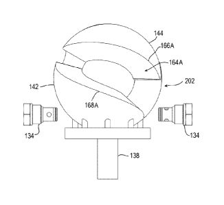
Looking to the example shown in Fig. 10, it can be seen how the stator
142 may be fixedly attached to the lower housing 124 by way of a plurality of
fasteners 146. The rotor 144 is generally allowed to move in a nutating motion
about the lower portion of the shaft 138 as will be discussed in detail. A
stability
ring 148 may be utilized to provide a better connection between the housing
120
and the stator 142; and to retain lower bearing 196.
CA 02903906 2015-09-03
WO 2014/139036
PCT/CA2014/050287
29
Continuing with a review of the components shown in Fig. 10, it can be
seen that the shaft 138 comprises a lower portion 150 and an upper portion 152
in this example, with a bend there between generally centered upon a spherical
surface 154. Again, this example shows a bent shaft variation similar to that
shown in reference to Figs. 1-6.
As can be further seen in Fig. 10, in the rotational position shown, the
stator 142 comprises an overhang portion 156 which can more easily be
understood by looking to Figs. 16 or 19 were a distal end of the lobe 158 sits
circumferentially offset from the associated valley 160. This overhang
arrangement is pointed out as it may create some confusion in the cutaway view
of Fig. 10. In addition, it can be seen how a radially outward spherical
surface
162 of the rotor 144 blocks and seals the port 130 at least at one point in
nutation. In this configuration, when used as a fluid pump or compressor, the
port
130 may be utilized as an inlet port and as the rotor 144 nutates to a
position
wherein the port 130 is blocked, continued nutation will reduce the capacity
of the
associated displacement chamber 164 between a lower surface 166 of the rotor
144 and an upper surface 168 of the stator 142. As the capacity of the
associated displacement chamber 164 continues to reduce, fluid within the
displacement chamber 164 will be forced through the check valve 134 through
the port 132. Further discussion of the relative motion of the stator 142 in
regards
to the rotor 144 will follow, and the effects of the nutating rotor in
combination
with the stator and housing on fluid displacement will be better understood.
As with the previous example, the example shown in Fig. 10 utilizes an
upper bearing 170 which is held in place partially by way of a bearing keeper
172. Fluid seals 174 may be provided between the rotor 144 and the shaft 138
as
well as between the rotor 144 and a spherical surface 176 of the housing 120
to
reduce fluid flow past the bearing 170.
Looking to Fig. 11 and hidden line Fig. 12, the lower housing component
124 is shown with the upper housing component 122 and rotor assembly 180
removed along with the check valve 134. In these views, threaded voids 178 can
be seen quite clearly as configured for receiving a threaded portion of
fasteners
CA 02903906 2015-09-03
WO 2014/139036
PCT/CA2014/050287
126. Likewise, clearance voids 182 are shown allowing for passage of fasteners
146. Also shown are fluid ports 184. These fluid ports allowed fluid
communication to ports 132 at a position adjacent check valves 134 which allow
one way passage of fluids with the chamber 164 previously discussed.
5 Fig. 10
also shows a lower bearing 196 which is held in place by a bearing
keeper 198. The bearing keeper 198 engages a channel 194 as seen in Figs. 21-
23.
Figures 13-15 show the rotor assembly 180 and check valves 134
removed from the housing 122. Also shown in these views are the rotor 144,
10 stator 142, shaft 138, stability ring 148, and fasteners 146. One seal
point 186 is
shown between the rotor 144 and stator 142. In the rotor position of Fig. 13
this
seal point 186 is accomplished where the lobe 158 of the rotor 144 seals with
the
lobe 158' of the stator 142. In this disclosure, components of the stator
having
similar components on the rotor will be denoted with an apostrophe (`). For
15 example, the lobe 158 of the rotor is similar to (and in some
applications is
substantially identical to) the lobe 158' of the stator. In Fig. 14, the
opposing
circumferential side of the rotor assembly 180 is shown in the same nutational
position. At this side a seal point 188 is seen between the lobe 158 of the
rotor
144 and the valley 160' of the stator 142. While the term "seal point", is
used
20 herein, actual face-to-face contact may not be achieved between the
surfaces. A
very slight interference gap (fluid seal) may be provided between the surfaces
in
some applications. In other applications, the rotor 144 and or stator 142 may
be
formed slightly oversized, upon which nutation of the rotor 144 relative to
the
stator 142 and potentially inner surface 176 of the housing 120 results in an
initial
25 wear-in of the surfaces similar to common piston engines. This will
result in
substantially no gap between the surfaces once the "wear-in" period is
completed. The relative movement of the rotor 144 relative to the stator 142
will
be disclosed in more detail.
Looking to Figs. 16-20 the rotor is shown removed from the other
30 components to show the surfaces thereof including the lobes 158, and
valleys
160. It is to be understood that the opposing and cooperating stator may have
CA 02903906 2015-09-03
WO 2014/139036
PCT/CA2014/050287
31
similar or substantially identical lobes and valleys forming the face of the
stator.
In addition, an inner substantially cylindrical surface 192 is provided for
contact
with the bearing 170 and bearing keeper 172.
Figures 21- 23 show one example of a bent shaft 138. This bent shaft 138
may be used with the other components shown herein in several combinations.
These figures clearly show the spherical surface 154 positioned between the
upper portion 152 and the lower portion 150. In addition, the thread 194 for
the
bearing keeper or lock nut to be tightened 196 can clearly be seen.
Figures 24-29 show one example of the upper housing component 122. In
Fig. 27, the ports 130 and the substantially spherical inner surface 199 which
may be contiguous with surface 176 can be clearly seen.
Figures 30-50 show the rotor assembly in several nutational positions.
Each position is shown in three views so that for example Figs. 30-32 show the
rotor 144 in a first position 200 relative to the stator 146 and attached
components. Figs. 33-35 show the stator 146 from the same relative position,
but
where the rotor 144 and attached components are in a second nutational
position
202. Likewise, Figs. 36-38 show a third nutational position 204, Figs. 39-41
show
a fourth nutational position 206, Figs. 42-44 shown a fifth nutational
position 208,
Figs. 45-47 show a sixth nutational position 210, and Figs. 48-50 show a
seventh
nutational position 212. Following the seventh nutational position 212, the
rotor
144 will generally nutate to the first position 200, and the nutational cycle
will
repeat. In Figs. 31, 34, 37, 40, 43, 46, and 49, the check valves 134 are not
shown so that the stator 142 and rotor 144 can be more clearly seen.
Figures 30-50 show a rotor 144 and stator 142 each with two lobes 158(A-
B)/158'(A-B) and two valleys 160(A-B)/160'(A-B) although other configurations
can also be utilized such as the single lobe example shown in Fig. 54, the six
lobe example of Fig. 63, or the four lobe example shown in Fig. 76. In this
disclosure, where there are similar sub-components on a parent component,
specific sub-components may be denoted with a letter suffix. For example,
lobes
158A and 158B are both on the rotor 144, but on generally opposing
circumferential sides.
CA 02903906 2015-09-03
WO 2014/139036
PCT/CA2014/050287
32
The relative seal locations/positions between the stator 142 and rotor 144
will now be disclosed in reference to the rotational cycle shown in Figs. 30-
50.
While each drawing only shows one side of the rotor assembly 180, it can be
appreciated that in this example, seal points are formed on opposing sides of
the
rotor assembly 180. These two seal points form chambers 164A/164B on either
circumferential side of the rotor assembly 180.
Looking to Figs. 30-32, a seal point 214 is shown between the axial face
216' of the stator 142 and an opposing axial face 216 of the rotor 144. For
reference, the axial faces 216 and 216 generally correspond to the contact
faces
(24) of US Patent 5,755,196 (196) while the upper surfaces 168 of the stator
and
lower surfaces 166 of the rotor 144 generally compare to the side of faces 26
of
the '196 patent. As will be understood there are significant differences
between
the rotors and stators of this disclosure and those rotors disclosed in the
'196
patent. One difference is seen in that sealing may be accomplished between the
facing surfaces 166/168 of the rotor and stator as well as between the axial
faces
216/216' of facing lobes of the rotor and stator.
Looking to Fig. 31, it can be seen how a seal point 214 is formed between
the rotor 144 and the stator 142. As the shaft 138 rotates in the direction
indicated at direction 220, the rotor 144 will roll slightly resulting in only
a slight
repositioning of the seal location 214A along the axial face 216 of the rotor
144.
Due to the relative movement of the nutating rotor 144, the seal point 214
will
move/slide significantly down the axial face 216' of the stator in direction
of travel
222. Sealing will be maintained between the surfaces as understood by looking
to Fig. 34 where the volume of the chamber 164A is substantially reduced as
the
seal location 214 has repositioned substantially down the axial face 216.
In addition, a seal point 224 may form between surfaces 166 and 168 as
can be seen in Figs. 33-35. As the rotor 144 nutates, the seal point
repositions in
direction of travel 226 as surface 166B engages in substantially rolling
contact
with surface 168B, further reducing the volume of chamber 164B. The chamber
164 sealed on one side by the seal point 214 and on the other side by the seal
point 224 is adjacent to and in fluid contact with the port 132. The chamber
164B
CA 02903906 2015-09-03
WO 2014/139036
PCT/CA2014/050287
33
is defined then by the lower surface 166B, the upper surface 168B, the
spherical
surface 154, and the inner surface 176 (see Fig. 12) of the housing 120. As
the
rotor 144 continues to nutate, the seal point slides down the axial face 216'
in
direction of travel 222 and the chamber 164 continues to reduce in volume
forcing fluid out of the port 132. At the same time, the chamber 164A on the
opposing side of the rotor assembly 180 increases in volume, drawing more
fluid
there into, in one example through port 130. In this example, the port 130 is
positioned adjacent the upper surface 168A for inflow of fluids into the
adjoining
chamber.
Looking to Figs. 36-38, it can be seen that the chamber 164B has reduced
to a zero volume as seal points 214 and 224 coalesce at seal point 188. In
this
position, it can also be seen that surface 166A has formed a new seal point
224/230 therebetween. Seal point 224/230 bifurcates and moves in two opposing
directions once formed. Seal point 224 moves direction 226 as previously
discussed, while seal point 230 moves in the opposing direction. A chamber
164C is formed therebetween in fluid communication with one of the upper ports
130 to allow fluid thereinto. The lobe 158B of the rotor repositions away from
valley 160B in direction of travel 228. This allows fluid flow past the lobe
158.
Looking to Figs. 39-41, it can be seen that the seal point 224 has
repositioned in direction 226 towards the lobe 158'B, and the seal point 230
has
repositioned in a rolling/sliding manner towards the point of lobe 158'B. Lobe
158B continues to move away from valley 160B, as chamber 164A continues
toward a minimum volume position, and chamber 164B continues toward a
maximum volume position. Chamber 164C continues to increase in volume,
drawing fluid into the apparatus through port 130.
Looking to Figs. 42-44, it can be understood that as the rotor 144
continues to nutate, seal point 224 continues in direction 226 through rolling
contact between the face 166A of the rotor 144 and face 168A of the stator 142
as previously described. The volume of the chamber 164B continues to increase,
and the volume of the chamber 164A continues to decrease. In this example,
fluid continues to flow into the chamber 164C through the adjacent port 130,
and
CA 02903906 2015-09-03
WO 2014/139036
PCT/CA2014/050287
34
fluid continues to flow out of chamber 164B through the adjacent port 132.
Lobe
158B continues in relative motion direction 232 while the seal point 230
slides
down axial face 216.
Looking now to Figs. 45-47, the seal point 230 approaches the tips of both
lobes 158b and 158'B as the chamber 164B approaches the maximum volume
position and opposing chamber 164A approaches a minimum volume position.
Chamber 164C continues to increase and draw fluid thereinto.
Figs. 48-50 the last stage of the cycle is shown, where chamber 164B has
reached a maximum volume position, and chamber 164A has reached a
minimum volume position, dispelling substantially all of the fluid therein.
Seal
point 230 has reached the points of lobes 158B and 158'B. Immediately past
this
position, surfaces 166A and 168A separate, opening seal point 224 as can be
seen looking to Fig. 30. Chamber 164C is then open to lobe 158'B and becomes
the new chamber 164B shown in Fig. 31. The cycle then repeats for each
.. revolution of the shaft 138.
Figures 30-50 show that the distal tip of lobe tip 158B of the rotor 144
scribes a substantially teardrop shaped path 234 in each cycle of nutation.
Therefore, in this example the axial face 216' of the lobe of the stator 142
as well
as the axial face 216 of the rotor 144 may also form a substantially teardrop
shape in cooperation with the adjacent valley to allow a seal therebetween as
the
volume of the adjacent chamber decreases in a compressor (pump) application,
or increases in an expander application. As previously discussed, the seal may
be a fluid seal, or a sliding contact seal between these surfaces. In other
examples, other shapes may be utilized such as the shape shown in Figs. 63-64.
It should be noted that the path 234 presented in Fig. 49 shows straight lines
interconnecting the specific positions of the lobe tip shown in Figs. 31, 34,
37, 40,
43, 46 and 49. It can be understood that the actual path of the lobe tip will
be
arcuate following the nutation progression of the rotor 144, and generally not
linear segments.
Looking to Fig. 51, another example of a housing 240 is shown. In this
example the housing 240 comprises an upper housing 242 and a lower housing
CA 02903906 2015-09-03
WO 2014/139036
PCT/CA2014/050287
244. The upper housing 242 of this example comprises a port 246 which may
have a threaded surface 248 for connection of a check valve or other fluid
connection as previously discussed. Similarly, the lower housing 244 comprises
a port 250 which may also have a threaded surface 252 for connection of a
5 check valve or other fluid connection. Also be appreciated that the
example
shown in Fig. 51 comprises a shaft 254 having a keyway 256 each protruding
from the housing 240 for attachment of an engine, motor, or driven shaft. It
can
also be appreciated that the port 250 is offset 258 from a plane passing
through
the axis 260 of the shaft 254 in the center of the port 246. A similar example
is
10 shown and described relative to Fig. 9.
Looking to Fig. 52, the housing 240 is shown cut along line 52-52 of Fig.
51 such that the port 246 is shown however, only a small portion of the port
250
is shown. As with prior examples, in this example a rotor 262 is shown having
a
generally spherical outer surface 264. The apparatus also comprises a stator
266
15 fixed to the lower housing 244 through a plurality of fasteners
equivalent in
function to the fasteners 196 previously discussed in reference to Fig. 8.
These
fasteners pass through clearance holes 268 and are received by threaded
surfaces 270 in the stator 266. A static seal 272 may be provided to prohibit
fluid
flow outward between the upper housing 242 and lower housing 244. Likewise,
20 static seal 274 is disposed between the stator 266 and the lower housing
244 to
seal there between. Seals 276 may also be provided between the stator 274 and
the shaft 254. To reduce friction and maintain alignment, a shaft bearing 278
may
be provided between the housing 254 or stator 274 and the shaft 254. A bearing
keeper 280 may also be provided and engage a thread 282 in the shaft 254. A
25 similar keeper 284 may be provided at the opposing end of the shaft 254
as
shown in Fig. 53. The keeper 294 in one form engages a channel 286 in a shaft
254. In this example, the shaft 254 is a straight, or through shaft, and not a
bent
shaft such as the bent shaft shown in Fig. 10.
Fig. 53 shows a detail view of the upper interior portion (region 53) of the
30 housing 240. As shown, a precession cam 288 is shown as engaging a
keyway
290 such as by application of a key 292 between a keyway formed in the
CA 02903906 2015-09-03
WO 2014/139036
PCT/CA2014/050287
36
precession cam 288 and the keyway 290 of the shaft 254 in a manner well-
known in the art. A seal 294 may be provided between the surface of the rotor
262 and the inner surface 296 of the upper housing 240 to prohibit or reduce
fluid
flow there between. As the precession cam 288 rotates with the shaft 254, and
as the rotor 262 is prohibited from substantial rotation by engagement of the
lobes of the rotor 262 engaging the lobes on the stator 274, the rotor 262
will
nutate about the surface of the stator. A bearing 298 may be provided between
the precession cam 288 and the rotor 262 to reduce friction there between.
Additionally, an eccentric cap 300 may be positioned between the precession
cam 288 and the keeper 284. To prohibit or reduce fluid flow between
components, seals 302, 304, and 306 may be provided between the surfaces
adjacent thereto.
As the shaft 254 is not centered upon the axis 308 of the precession cam
288, and whereas there is an alpha (a) angle 310 between the axis 260 of the
shaft 254 and the axis 288 of the precession cam 288, the rotor 262 will
nutate
about the stator 274 in a manner substantially equivalent to that shown in the
previous examples.
Figs. 54-56 show a rotor/stator 262/274 with surfaces very similar to those
shown in Figs. 16-20 such as a lobe 312 adjacent a valley 314. The lobe 312
comprises an axial face 316 similar to the axial face 216 of Fig. 16 and side
face
318 similar to the face 168/166 of Fig. 16. In addition, a surface 320 is
formed to
engage the shaft 254 when the component is used as a stator or to engage the
precession cam 288 when used as a rotor. While this example uses a single lobe
rotor/stator, the relative motion of a rotor of this design to a stator of
this design is
substantially equivalent to that discussed in reference to Figs. 30-50 wherein
a
teardrop motion is encountered by the rotor 262 relative to a stator 274. As
with
the previous example, the axial face 316 of lobe 312 of the rotor/stator
engages
in sliding contact with the axial face 316 of the opposing stator/rotor and
the side
face 318 of the rotor/stator engages in substantially rolling contact with the
side
face 318 of the opposing stator/rotor. This contact has been well discussed in
reference to Figs. 30/50 and need not be substantially repeated. A channel 322
CA 02903906 2015-09-03
WO 2014/139036
PCT/CA2014/050287
37
may be provided for contact with the seal 294 previously disclosed. When the
lobe and valley configuration shown in Figs. 54-56 is utilized as a stator
274, the
channel 322 and associated components may be replaced by structures more
easily understood by looking to Fig. 52.
As with the examples shown elsewhere in this disclosure, including those
depicted in Figs. 16-20, the axial face of the rotor 262 and/or stator 274 may
be a
teardrop shape as previously discussed, while the surface 318 may be a
spherical involute surface. Such surfaces are disclosed in applicant's prior
patents and patent applications which are publicly available.
Figures 57-60 generally show a rotor-stator assembly utilizing the through
shaft 254 and other components of Fig. 52. Fig. 57 generally shows an
isometric
view wherein the rotor 262 seals with the stator 274 at seal point 326 to
prohibit
fluid flow therebetween. In the face view of Fig. 58, the seal point 326 can
be
seen between side faces 318 and 318'. The lobe 312 of the rotor 262 has
repositioned slightly away from the valley 314' in a position similar to the
fourth
position shown in Fig. 40 of a two-lobe assembly. Fig. 59 generally shows the
same surfaces in the same relative positions however the angle of view of the
assembly is slightly rotated. Likewise, Fig. 60 shows a view at 180
opposition
circumferentially from that shown in Fig. 58 and shows a relatively large
portion
of a chamber 320 formed by the rotor 262, stator 274, central ball surface 332
of
the shaft 256, and the inner surface 296 of the housing 240. The surface 296
of
the housing 240 is not shown in this drawing but is shown quite clearly in
Figs. 52
and 53. It can be appreciated that as the rotor 262 nutates, the volume of the
chamber 330 increases and decreases in size as previously described in some
detail.
Another example of the disclosed apparatus is shown in Figs. 61-71. This
example utilizes a different shaft assembly, novel porting, and a unique
housing
assembly as well as other novel features. Looking to Fig. 61 the device is
shown
comprising a housing 350 which in turn generally comprises an upper housing
component 352 and lower housing 354 held in place by way of a plurality of
fasteners 356. In one form, an upper plate 358 having a port 360 is used to
CA 02903906 2015-09-03
WO 2014/139036
PCT/CA2014/050287
38
complete the inner chamber 362 and seal the components therein. A port 364
may be provided through the housing 350 wherein the port 364 cooperates with
the port 360 to allow for fluid flow through the apparatus as a pump
(compressor)
in a first direction or as an expander in a second direction. As with the
ports
.. previously disclosed, the ports 360 and 364 may utilize threaded surfaces
366/368 respectively for attachment of check valves or other fluid couplings.
As
with the previous examples, a main shaft 370 may extend outward of the housing
350.
Looking to Fig. 62, a cutaway view of the apparatus taken along line 62-62
Fig. 61 is shown so that the inner components can be more easily viewed. Where
some of these components are difficult to view in this drawing, the reader is
directed to Fig. 84 which discloses a very similar apparatus with some
additional
alternate components. In particular, the apparatus shown in Fig. 62 is
generally a
variant of the previous bent shaft examples. There are significant differences
.. between this example and the preceding examples, for instance, while the
previous bent shaft examples utilize a shaft with a unitary structure, it can
be
understood that the shaft assembly of this disclosure may comprise a main
shaft
370 and a removably attached offset shaft 374. In one example, the collar 400
functions as the nutating shaft, and the shaft 374 is affixed to the shaft 370
as
disclosed in more detail. The unitary structure shaft of the previous example,
and
the composite shaft of this example, are generally interchangeable. The shaft
370 in one example comprises a keyway 372 so as to facilitate the shaft 370 to
be driven by an exterior engine, motor, etc. The offset shaft 374 has an axis
380
that is at an alpha (a) angle 376 with the axis 378 of the main shaft 370.
This
alpha (a) angle and the function served by engagement of the rotor 406 to the
stator 392 at such an alpha (a) angle is discussed above, and in applicant's
prior
patent disclosures. In one form, the offset shaft 374 has a male threaded
portion
382 which threads into a female threaded portion 384 of the shaft 370 as can
be
understood by looking to Figs. 65-68 to allow removable attachment thereto. In
one example, shaft 374 is comprised of a threaded fastener (bolt), which
passes
through collar (shaft) 400 as shown also in Fig 84. In the bolt/collar example
CA 02903906 2015-09-03
WO 2014/139036
PCT/CA2014/050287
39
shown, the shaft (bolt) 374 retains the upper shaft (collar) 400 in position.
In one
example, the collar 400 is press fit into the ball 418, and the bolt is
threaded into
the ball 418. It is also conceived that the bolt 374 and collar 400 are formed
as a
unitary shaft. The offset shaft 374 may also have a non-cylindrical portion
388 for
.. engagement with a tightening tool such as a wrench. In the example shown,
the
non-cylindrical portion 388 comprises a hexagonal female fitting for
acceptance
of an Allen-style wrench. In other examples, the noncircular portion 388 may
comprise a hexagonal or other (preferably non-cylindrical) shaped male fitting
for
use with standard (such as socket or open end) wrenches. Many such
noncircular fittings and surfaces are known in the art.
In another example the offset shaft 374 and/or collar 400 may be precision
fit or interference (press) fit into the void 384 and an indexing pin may be
fit
through the spherical surface 418 and shaft 372, thus retaining the offset
shaft
374 there within.
Returning to Fig. 62, can be seen in this example how the upper plate
350, upper housing 352 and lower housing 384 form an inner chamber 362
wherein many of the components are positioned.
In the example of Fig. 62, the shaft 370 is attached through the lower
housing 354 and through a collar portion 390 of the stator 392. The stator 392
.. may be fastened to the lower housing 384 by way of a plurality of fasteners
394
which pass through voids in the lower housing 354 and may engage threaded
portions of the stator 392. A static seal 396 may be provided between the
stator
392 and the lower housing 354 to reduce or eliminate fluid flow there between.
A
seal 556 may be provided between the stator 392 and the shaft 370. Likewise, a
static seal 398 may be provided between the plate 350 and the upper housing
352. Another static seal 399 may be provided between the upper housing 352
and the lower housing 354.
As the main shaft 370 rotates, the offset shaft 374 precesses about the
axis 370 of the main shaft 370. A collar 400 provided about the offset shaft
374
and a plurality of bearings 402/404 may be provided between the collar 400 and
the rotor 406 to reduce friction there between. A keeper 412 may be utilized
to
CA 02903906 2015-09-03
WO 2014/139036
PCT/CA2014/050287
maintain the bearings 402 in the correct position on the offset shaft 374. A
channel 414 may be utilized to hold the keeper 412 in position on the shaft.
In
one example, lock nut and lock washer (bearing keeper 412) are tightened on a
thread (shown as channel 414) located on the outside diameter of collar 400.
In
5 this example, the lock nut is tightened down against a sleeve spacer
ring. The
spacer ring presses against an inner race of the upper taper roller bearing
402.
This spacer ring in one example also serves as a sealing surface for an upper
rotary seal 556 that may be contained in the annular cavity formed by a small
end cap 558. In one example, the end cap 558 is adjacent the lock washer/ lock
10 nut (keeper 412). In Fig. 88 are shown voids 348 in the end cap 558
where
fasteners (bolts) pass and therefore fasten the end cap 558 to r0t0r406. In
Fig.
88, some of the voids 348 are obscured by the wings (blade surfaces) 594.
These voids 348 may receive fasteners which fasten the end cap 558 to the
upper sleeve of the rotor 406. Another keeper 454 may be utilized to maintain
15 bearings 456 and 458 in position relative to the housing 350 and shaft
370. A
channel 460 (Fig. 68) may be formed in the shaft 370 to retain the keeper 458
in
place. In one example, the channel 460 is an undercut provided adjacent male
threads on the outside of the shaft 370. These male threads are provided to
thread and tighten the keeper 454 (lock nut, lock washer) on shaft 370. As the
20 lobes 408 between valleys 410 of the rotor 406 engage the lobes 408'
between
valleys 410' of the stator 392, and as the stator 392 is affixed to the
housing, the
rotor 406 is therefore substantially prohibited from rotation relative to the
housing
350. The rotor 406 therefore experiences nutational movement in relation to
the
stator 392 as with the previous examples.
25 Another substantial difference between this example and previous
examples is in the porting arrangement. In particular, when used as a pump or
compressor, the port 360 in the plate 358, or other portion of the upper
housing
352 functions as an inlet port and the fluid flows past the upper portion of
the
rotor 406 and passes through ports 416 which can also be seen in Fig. 64. A
30 dynamic seal 422 may be provided to reduce or eliminate fluid flow
between the
ports 416 and the bearings 402/404. The fluid enters chambers provided
CA 02903906 2015-09-03
WO 2014/139036
PCT/CA2014/050287
41
between the face of the rotor and the opposing face of the stator 392 as the
chamber in question increases in volume.
Looking to Figs. 65-68 it can be seen how the main rotor 370 comprises a
spherical surface or ball 418 with features unique to those shown in previous
examples. The ball surface 418 comprises a substantially planar surface 420
generally normal to the offset axis 380 and having the surface 384 provided
there
through. To facilitate porting through the ball surface of 418, cutaway
portion 426
is provided in the surface 420 and extended downward to form port surface 424
which allows fluid flow from the ports 416 to an enlarging chamber between the
rotor 406 and the stator 392. A manifold is therefore provided in some
examples
wherein the annular chamber 596 is in communication with the ports 416. This
annular chamber 596 in one example is also is in fluid communication with the
port surface 424. Annular chamber 596 is perhaps best seen in Fig. 84. A
rotary
seal 422 may be fit into an annular gap at this position. In one example, as
the
shaft 370 rotates, groove 426 rotates relative to the (6) lobe chambers. When
the groove 438 passes any particular "valley" opposing lobes, the apparatus is
allowed to intake fluid therebetween. As the shaft 370 rotates, the volume of
the
chambers between opposing lobes/valleys decreases, and the apparatus
corresponds to a discharge stroke. In some examples, the design reduces or
eliminates the necessity for a check valve at the port 360.
As the shaft 370 rotates along with the ball 418, the ports 416 are
sequentially allowed fluid communication with chambers between the stator 392
and rotor 406. Likewise, on the opposing circumferential side of the ball 418
is
provided an asymmetric port surface 438. Although at the upper edge 440 the
port surface 438 is sealed to the inner spherical surface 442 and fluid flow
is
therefore prohibited to the ports 416 of the rotor 406, the lower surface 444
is
aligned with a port channel 428 through rotation of the shaft and the port
channel
is in fluid communication with ports 430 through the outer spherical surface
446
of the stator 392. As the stator 392 is affixed to the lower housing 354, it
can be
appreciated that the ports 430 are aligned with or in fluid communication with
ports 364 to allow fluid flow through the housing 350.
CA 02903906 2015-09-03
WO 2014/139036
PCT/CA2014/050287
42
Looking to Figs. 63 and 64 it can be appreciated that the axial faces 432
and 432 of the rotor 406 and stator 292 respectively have a significant cutout
portion which will not engage the axial face of the opposing surface through
nutation. However, at the apex of the teardrop shape scribed by the tip of the
opposing lobe 408 of the rotor 406 relative to the stator 292 axial seal
surfaces
436/436' are provided for sealing of the adjacent chamber at one short segment
of nutation. Due in part to the nature of the port surfaces 424 and 438
rotating
with the shaft 370, a novel sealing system can be utilized. In particular, as
each
upper surface 448 of each lobe 408 provided on the rotor 406 engages a
cooperating upper surface 448' on the stator 392 as a rolling seal equivalent
to
the seal between the surfaces 168 disclosed above it can be appreciated that
in
a pumping or compressing application, the chambers will reduce in volume and
at least at the apex point of nutation, fluid will be generally forced past
the port
surface 438 in the shaft 370 out through ports 364. Likewise, on the other
circumferential side as the volume of the chambers there increase in volume
and
as the port surface 424 is allowed fluid communication with the ports 416 and
360, it can be appreciated that a pumping or compressing action will be
achieved. Additionally, this configuration allows fluid to pass beyond the
lobes
408/408' during a significant part of the nutation and will therefore provide
a more
continuous pumping action and may be achieved in other examples shown here
in. Additionally, allowing some fluid to flow past the adjacent lobes 408/408'
may
significantly reduce backlash.
Another novel feature is shown in reference to the rotor 406. It can be
seen how the radially outward surface 450 of the rotor 406 comprises a
recessed
region 434 to significantly reduce machining tolerances etc. To maintain a
seal
between the radially outward surface 450 of the rotor 406 and the inner
surface
438 of the upper housing component 352 a radially protruding seal surface 452
may be provided which forms a seal either contact or fluid between the rotor
406
and the surface 438 of the upper housing component 352 as well is an extension
of the surface 438 in the lower housing component if so provided. In one form,
the raised housing seal 452 may also be utilized wherein an abradable coating
is
CA 02903906 2015-09-03
WO 2014/139036
PCT/CA2014/050287
43
provided on the inside spherical surface of the housing 352. In such an
application, the housing seal 452 may be formed of a hard metal material so as
to more easily abrade the coating in order to produce a tight fitting gap seal
with
the housing. Such an abradable coating may alternatively, or in combination be
applied to the rotor and/ or stator (as well as the housing). While such
abradable
coatings were previously impractical in nutating or rotating positive
displacement
devices, by utilizing the indexing/power transfer systems disclosed herein,
such
abradable coatings are practical.
Looking to Figs. 72-80, another example is disclosed with additional novel
components in combination with several components disclosed above. Looking
to Fig. 72, it can be seen how a housing 462 is provided which in this example
comprises an upper housing 464, an upper median housing 466, a lower median
housing 467 and a lower housing 469. Although the fastening mechanism
between these components is not shown, it can be appreciated by looking to the
previous examples. Alternatively, as with the previous examples, other
fastening
methods can be utilized such as adhesives, welding, brazing, etc.
As with the previous examples, lower ports 520 and upper ports 518 may
be provided in fluid communication with chambers 468 and 470 respectively
between the stator 472 and the rotor 474. As the rotor 474 and stator 472 are
.. similar in form and function to the rotor and stator shown in Figs. 4-6,
the
chambers 468 and 470 provided between the lobes can be understood by
reviewing the disclosure above. In one form, check valves 476 may be provided
for one-way flow through specific ports, and to provide a breaking pressure.
In
some instances where specific check valves are referenced in this disclosure,
an
alphabetic suffix will be utilized to indicate a specific check valve. For
example,
the check valves are generally labeled 476 but one specific check valve is
labeled as check valve 476A shown in Fig. 78. Check valve 476 is specifically
referenced again below, and thus a specific label is used. As can be clearly
seen
in Figs. 78-80 the check valves utilized herein comprise a fluid flow surface
478
which is in fluid contact with a valve member 480 to allow fluid passed the
valve
480 in one direction only. As such, the outer end portion 482 of the check
valve
CA 02903906 2015-09-03
WO 2014/139036
PCT/CA2014/050287
44
476 may not allow fluid to pass through the port opening into which the valve
476
is fitted. Therefore, as can be seen in Fig. 73, a channel 484 may be ported
(in
fluid communication) through the housing at 486 and generally provide a
common inlet (or outlet) for alternate check valves 476A connected to the
fluid
channel 484 by way of fluid sub-channel 488. Likewise, a lower fluid channel
490
may connect via fluid sub-channels 492 to alternate check valves 476B. A
housing port 494 may be provided with a threaded or other fluid coupling
surface
for attachment to piping or other apparatus. In this way, a common inlet and
common outlets are provided in the housing allowing for easy fluid
connectivity.
As can be clearly understood by looking to Fig. 73, there are several
similarities between this example and the example shown in Fig. 62. The
apparatus comprises a shaft 496 which may include a keyway 498. While the
example shown in Fig. 62 is shown as being driven from the bottom (bottom
shaft), the example of Figs. 72-80 is shown driven from the top (top shaft).
In
some applications, the apparatus of either example could easily be used in a
side
oriented or inverted position, depending on the application and fluid flow
required. The shaft 496 comprises or is fixed to an precession cam 500 with an
offset shaft 502 engaged therein with bearing 504 positioned between the
offset
shaft 502 and the precession cam 500 so as to allow free rotation of the
offset
shaft 502 relative to the precession cam 500. As can be more easily seen in
Fig.
79, the offset shaft 502 comprises a non-cylindrical surface 508 which
functions
in the same way as the non-cylindrical surface 388 previously discussed. The
offset shaft 502 passes through a rotor 474 with a bearing 506 positioned
there
between to allow free rotation of the offset shaft 502 relative to the rotor
474. In
this way, the rotor 474 is allowed to nutate relative to the stator 472. As
with the
example of Fig. 62, lobes 508 and valleys 510 of opposing rotor 474 and stator
472 prohibit substantial rotation of the rotor 474 relative to the stator 472.
In one
application, the check valves 476A provide for fluid to enter the chambers 470
between the valley 510A of the rotor 474 and the lobe 508'A of the stator 472.
As
can be seen in Fig. 78 seal points 512, 514, and 516 are formed at this
position
of nutation on either circumferential side of the chamber 468. As discussed
CA 02903906 2015-09-03
WO 2014/139036
PCT/CA2014/050287
relative to Figs. 30-50 in combination with a review of US Patent 6,705,161
these
seal points and the effect they have on fluid flow can be understood, which
describes quite well this particular example of a lobe/valley combination and
the
seal points there between with slight modifications.
5 Fig. 77 also shows one example of a turbulence generating surface 650
which may be applied to the non-sealing surfaces of the rotor and or stator to
generate localized vortexes on the surface thereof. Such surfaces reduce fluid
flow hindrance, and reduce contaminate build in some applications. One
disclosure of such turbulence surfaces is presented in US Patent 4,907,765.
10 Looking to Fig. 73, it can be appreciated that a system of static and
dynamic seals similar to those used in the previous examples may be used. In
particular, static seals of 522 and 524 are utilized on either radially
outward edge
of the fluid channel 484 to reduce or eliminate fluid flow between the upper
housing 464 and the upper median housing 466. Likewise, a static seal 526 may
15 .. be utilized between the upper median housing 466 and the lower median
housing
467. A similar static seal 528 may be utilized between the lower median
housing
467 and the lower housing 469. A static seal 530 may also be utilized between
the stator 472 and the lower median housing 467. Additionally, dynamic seals
may be provided between the shaft 496 and the upper housing 464 as well as
20 between the lower shaft 532 and the lower housing 470. Dynamic (shaft)
seals
may also be utilized between the stator 472 and the shaft 544. A keeper (lock
nut and lock washer) may be utilized, and may engage channel 544 of Fig 73.
The channel 544 in one example represents threads on the outside diameter of
the lower shaft 532 for attachment of the bearing keeper. Looking to the top
25 portion of Fig. 73, it can be seen that the shaft 496 comprises a
bearing surface
534 adjacent and offset from a bearing surface 536 on the upper housing 464. A
bearing similar to the bearing 404 shown in Fig. 62 may be utilized to reduce
friction between these surfaces.
Looking to the lower portion of Fig. 73 it can be seen how the ball surface
30 538 at the center of the rotor 474 and stator 472 has a lower shaft 532
extending
there from through the bottom portion of the lower housing 469. A bearing 540
CA 02903906 2015-09-03
WO 2014/139036
PCT/CA2014/050287
46
may be provided at this location to reduce frictional losses there between.
Also,
fasteners 542 can be seen of equivalent function to the fasteners 146 of Fig.
10
to maintain position of the stator 472 relative to the housing 462. A
channel/thread 544 may be provided in the lower portion of the lower shaft of
532
for attachment of a keeper to maintain the bearing and position similar to the
channel/thread 546 in the upper portion of the shaft 496. In one form, the
lower
shaft 532 may be driven in conjunction with the shaft 496 to increase
available
port to the rotor 474 or may alternatively drive a secondary component such as
a
second apparatus such as a second pump, compressor, or expander, fitted there
below and attached to be driven simultaneously with the apparatus shown in
Fig.
73.
One additional novel feature of Fig. 73 is shown in the dynamic seal
component 548 which is fitted to the upper portion of the rotor 474. The
dynamic
seal component 548 of one example forms a seal between the rotor 474 and the
inner spherical surface of the upper housing 464. Static seals 550 and 552 may
be utilized between the rotor 474 and the dynamic seal component 548 to reduce
or prohibit fluid flow there between.
As with the examples described above, this example may utilize a
recessed portion 554 on the radially outward surface of the rotor and a
radially
protruding sealing edge 556. These are similar in function to the surface 434
and
seal 436 described above.
Looking to Figs. 81-83 are shown novel components which can be
combined with the examples shown above or those disclosed in applicants other
inventions. In this example 560, a housing 562 is shown in a highly schematic
.. manner. A shaft 564 may be provided with a keyway 566 for attachment to
other
apparatuses as previously disclosed. The shaft 564 is shown attached to a
rotor
568 having lobes and valleys which engage opposing lobes and valleys on a
rotor/stator 570. A second shaft 572 is attached to the rotor/stator 570. Each
of
the rotors 568 and 570 comprise a spherical outer surface 574 to engage a
spherical inner surface 576 of the housing 562. The novel feature shown herein
is that the shafts 564 and 572 are hollow as comprising an inner surface 578
and
CA 02903906 2015-09-03
WO 2014/139036
PCT/CA2014/050287
47
580 respectively through the length of the shaft 564/572. As shown, a fluid
channel 582 may extend between the fluid channel surface 578 of the shaft 564
towards a chamber 584 between the lobes and valleys of the rotors 568/570
which at the position shown in Fig. 82 is at a minimum volume position.
Likewise,
the fluid channel surface 580 extends towards a fluid channel 586 extending
into
a chamber 588 between the lobes and the valleys of the rotors 568/570 as
shown in Fig. 82 at a maximum volume position. It can therefore be understood
that the fluid channels may comprise analysts and outlets provided through the
shafts 564/572.
Looking to Fig. 83 the shafts and spherical surface 574 can be seen with
the housing 562 removed. Here, it can be appreciated that in this example as
the
channels 582 and 586 are provided between the rotor 568 and rotor 570 at the
maximum volume position the channels are larger in cross section than they are
at the minimum volume position. Looking to Fig. 83, it can be seen that the
.. channel 586 is substantially larger than the channel 582. This gap
differential can
also be seen in Fig. 82.
As previously discussed, the example 590 shown in Figs. 84-89 utilizes
many of the same components as previously discussed relative to Figs. 61-71.
In
addition, this example 590 uses a nutating booster pump 44 previously
mentioned but shown in detail herein. As can be appreciated, the apparatus
utilizes a plurality of arcuate blades 48 which in this example are attached
to an
upper end of the offset shaft 400 and retained by bolt 374.
This example of these blades 48 are shown as arcuate members having a
very small portion at the shaft 374, they have a relatively large
circumferential
edge 592. In addition, while three cooperating blade surfaces 594 are shown,
one, two, or more than three blade surfaces 594 could alternatively be used.
Likewise, the blades may not be arcuate but may have some other shape which
generally directs fluid from the port 360 downward toward the ports 416 to
function as a booster pump. It can also be appreciated that while the rotor
406
nutates about the stator 392 as the blades 48 are substantially rigidly
attached to
the offset shaft 374 and as the offset shaft 374 is substantially rigidly
fixed to the
CA 02903906 2015-09-03
WO 2014/139036
PCT/CA2014/050287
48
shaft 370 the effective or relative motion of the blades 48 relative to the
housing
350 are a rotating motion rather than a wobbling or nutating motion.
Fig. 90 shows another example wherein the stator face 602 having lobes
604 and valleys 606 is formed as a unitary structure with the lower housing
608.
The lobes and valleys on the stator interact with lobes and valleys on the
rotor in
a manner as described above in several examples. This interaction is
substantially the same as described above, and therefore need not be repeated
here.
The lower housing in this example has no opening in the bottom thereof
as the housing is side-ported as can be seen in the figure. In one example a
female spherical surface 614 is provided for engagement with a male spherical
ball 616 of the rotor 618. The lower housing 608 in this example is positioned
adjacent and fastened to a median housing 610 with a static seal 612 there
between. In one example, a shim 730 may positioned between the lower housing
608 and the median housing 610. A similar shim 848 may be positioned between
the thrust bearing 850 and the upper housing 624 to take up any slack or gap
between the shoulder of the precession cam 636 and the upper (shaft) housing
624. In other words, the shim(s) 848 references the precession cam 636 to the
inner surface of the upper housing 624. For example, if there is determined to
be
0.025 mm (0.001 inch) of play in the shaft 630/precession cam between the
rotor
618 and the upper housing 624, then a 0.025 mm shim may be used to eliminate
the (vertical) play. Shims 726 may also be used on one or both sides of the
bearing 640 to position the precession cam 636 relative to the rotor 618. As
the
rotor 618 is coupled to the shaft 630 via an offset shaft 872, the shim(s) 726
will
align the precession cam along the offset shaft 872, thus adjusting the
apparatus
radially as well as vertically.
In one example the contact surface (where the two housing components
are in contact) is planar (in a geometric plane, flat). The shims disclosed
may be
flat plane layers. They may be produced of soft metals such as aluminum or
brass. While thinner or thicker shims may be used, thin shims are most
commonly from .001 inch to 1/4inch in thickness. In one example, the median
CA 02903906 2015-09-03
WO 2014/139036
PCT/CA2014/050287
49
housing 610 comprises a female spherical surface 620 in contact with a
radially
outward face of the rotor. By adding a shim 730, the spacing therebetween is
adjusted. In one example, a dynamic seal 622 may be provided to substantially
prohibit fluid flow between the radially outward surface of the rotor 618 and
the
surface 620 of the median housing 610
In the example shown in Fig. 90; an upper housing 624 is attached to the
median housing 610. In this example, a static seal 627 is provided there
between
to prohibit fluid flow between the upper housing 624 and the median housing
610. In one example, a shim 728 may be positioned between the lower housing
608 and the median housing 610 at a flat plane surface of each housing
component. As shown, dowel pins 770 may fit into surfaces defining (blind)
holes
772 in the upper housing 624, surfaces defining holes in the shim 728, and
surfaces defining (blind) holes 774 in the median housing 610. These holes may
be drilled after initial assembly of the apparatus. It may be beneficial to
rotate the
shaft 632, thus nutating the rotor, such that the upper (shaft) housing 624
will find
it's natural position relative to the median (rotor) housing 610. Once the
natural
position is found, the holes may be drilled and correct alignment assured.
Similarly, dowel pins 776 may fit into surfaces defining (blind) holes 778 in
the
median housing 610, surfaces defining holes 782 through the shim 730, and
surfaces defining (blind) holes 780 in the lower housing 608. Such dowel pins
may be replaced by threaded fasteners, rivets, etc. which each aid in
centralizing/aligning the components. In this example, the upper housing 624
has
a surface 626 defining an opening in the upper portion thereof. A bearing 628
may be press fit into the surface 626 and a shaft 630 engages the inner
surface
of the bearing 628 to reduce friction between the shaft 630 and the upper
housing 624 as the shaft 630 rotates. As with previous examples, a keyway 632
may be provided for rotation of the shaft 630 by a motor, engine, or similar
driving device. A channel 634 may also be provided for attachment of a bearing
keeper as shown in previous examples. As with previous examples, the channel
.. 634 may be representative of a threaded surface such that the keeper
comprises
a lock nut etc.
CA 02903906 2015-09-03
WO 2014/139036
PCT/CA2014/050287
The holes into which the dowel pins of the several examples are placed
may be blind holes, may be through holes, or a combination thereof. While an
interference fit is discussed, the dowel pins may alternatively be precision
fit,
press-fit, heat fit, or otherwise engage the dowel pin holes. In at least one
5 example, the dowel pin holes may be threaded, and the dowel pins replaced
with
threaded pins.
One assembly method using this arrangement may be accomplished by
the steps disclosed below.
Assembling a rotor sub assembly comprising in turn: a first rotor having a
10 frusta-spherical outer surface, lobes, and valleys; a shaft attached to
the first
rotor; a second rotor having a frusta-spherical outer surface co-centric with
the
frusta-spherical outer surface f the first rotor, lobes, and valleys; and a
center ball
attached at a radial center of the first rotor and second rotor. The steps
including
a step following assembly of the rotor sub-assembly of inserting the rotor sub
15 assembly into a housing comprising: a first housing portion having a
frusta-
spherical inner surface substantially identical in radius to the frusta-
spherical
outer surface of the first rotor; a second housing portion having a frusta-
spherical
inner surface substantially identical in radius to the frusta-spherical outer
surface
of the second rotor. This assembly step enacted prior to drilling or otherwise
20 machining the reference holes ensures alignment of the first housing
portion to
the second housing portion.
Following the step of inserting the rotor sub assembly into the housing, a
step of machining surfaces defining reference holes into the first housing
portion
and second housing portion is followed. As disclosed above, these reference
25 holes such as the dowel pin holes 778 may be blind holes, through holes,
threaded, or a combination thereof.
The alignment device may be a dowel pin press-fit into the reference hole,
may be a threaded bolt threaded into a female threaded portion of the
reference
hole providing clamping force between the first housing portion and the second
30 housing portion, or may be a threaded bolt positioned into a the
reference hole
CA 02903906 2015-09-03
WO 2014/139036
PCT/CA2014/050287
51
and having a nut threaded onto the bolt providing clamping force between the
first housing portion and the second housing portion.
In reference for example to Fig. 101 the assembly method disclosed
above may be used to assemble the rotor/inner shroud assembly. This
rotor/inner shroud assembly may then be inserted into outer housing 750. And
the upper housing 754 attached to the outer housing 750 in a similar manner.
In reference for example to Fig. 90; following the steps of inserting the
rotor sub assembly into the housing, the shaft 630 may be rotated while
allowing
the upper (first) housing portion 624 to find it's natural position relative
to the
median (second) housing portion 610. As these two components are not fixed to
each other, the upper housing 624 may be moved and find a position where it
does not move or bind the shaft relative to the median housing 610 during
rotation of the shaft 630. If such a natural position is not achieved, shims
726,
728, and/or 848 may be inserted. Once the natural position is found; in one
assembly method a step is accomplished of machining surfaces defining
reference holes 772/774 into the first housing portion and second housing
portion
and inserting pins 722, bolts, rods, or similar threaded fasteners thereinto.
In each of the examples, as the dowel pins may be made to very close
tolerances to a precision or interference fit. In one method of assembly, the
housing components may be assembled and aligned, at which point the holes
may be drilled and the dowel pins inserted into the holes. This assembly
method
will ensure alignment stability of the apparatus while in use.
The shims 728 and 730 allow for production/casting/machining tolerances
in that the inner surfaces of housing components 608, 610 and/or 624 may be
made undersized whereupon the shim(s) 728/730 are provided to account for the
under sizing of the housing components during assembly. If during assembly it
is
determined that additional, thinner, or thicker shim(s) are required, such
shims
may be easily manufactured to very high tolerances.
Looking to Fig. 101 is shown an example of a spinning apparatus rather
than nutating designs disclosed above. In the example of Fig. 101, each of the
shaft 734, upper rotor 732, lower rotor 736, and optional shroud 738 made of
52
upper section 740 and lower section 742 rotate or spin along direction 744.
Such
shrouds are disclosed in US Patent Publication 2011-0311351 A, December 22,
2011
which may be referred to for further details. As the shroud 738 of this
example is fixed to
the second rotor 736, there is relative rotational motion between the outer
housing 750 and the inner shroud 738. Bearings 746 and 748 reduce friction
between these components as well as to take up lateral and axial loading due
to
the differential pressures in the inner assembly. In one manufacturing
assembly
method, the rotors 732/736 are placed in the inner shroud 738 which is then
assembled into a sub-assembly which is inserted into the outer housing 750 at
which point the bearings etc., and upper housing 754 may be assembled.
As shown, dowel pins 784 may fit into surfaces defining (blind) holes 786
in the upper housing 754, surfaces defining holes 790 in the shim 752, and
surfaces defining (blind) holes 788 in the lower housing 750. Similarly, dowel
pins
792 may fit into surfaces defining (blind) holes 794 in the upper section 740
of
.. inner shroud 738, surfaces defining holes 798 through the shim 760, and
surfaces defining (blind) holes 796 in the lower section 742 of inner shroud
738.
The shims 756, and 757 being at right angles to the axis of rotation of the
rotor
736 not only adjust the vertical position of the rotor(s) 736/732, but also
adjust
the radial position of these elements and the shaft 734 relative to the upper
housing 754.
In this example as with the example of Fig. 90, shims may be utilized to
reduce tolerance stack up problems. For example shim(s) 752 may be positioned
between the outer housing 750 and an upper housing 754. In addition, shim(s)
756 may be provided between thrust bearing 748 and the lower outer surface
758 of the inner shroud 738 or second rotor 736. This shim 756 will impact
shaft
position relative to the outer housing 750. In addition, shim(s) 757 may be
provided between thrust bearing 748 and the outer housing 750. Likewise,
shim(s) 760 may be used between upper section 740 and lower section 742 of
the inner shroud 738. In the example shown, seals 762 are places adjacent
ports
764 in a rear-porting example.
CA 2903906 2019-07-23
CA 02903906 2015-09-03
WO 2014/139036
PCT/CA2014/050287
53
As an alternative to the shim(s) 752, shim(s) 840 may be used adjacent a
thrust bearing 842. In one form the thrust bearing 842 and shim(s) 840 are
held
in place via a top cap 844. The shim(s) 840 in one form may be adjacent a top
housing component 754. The shims 840 referencing the top cap 844 and/or shaft
734 to the upper housing 754 similar to the adjustment provided by the shim
848
disclosed in Fi. 90 and described above.
In the example of Fig. 98, similar shim(s) 768 may be used between the
upper housing 696 and lower housing 698. As with the examples above, it may
be desired to manufacture the upper housing 696 and lower housing 698
undersized to allow for the shim(s) 768.
In addition to shim 768, a shim 864 may be placed between the bearings
there above and the rotor 700. This shim 864 adjusts the position of the rotor
700
relative to the center ball 868 radially. As the annular ring gear 720 in one
example is fixed in position relative to the shaft 704, specifically the
offset shaft
706, a shim 864 will force the rotor 700 radially towards the center ball 868.
If
shaft seals for example malleable o-rings are provided between the center ball
868 and the rotor 700, these seals may be further compressed by the addition
of
a shim 864. A similar shim 866 may be placed between the a shoulder of the
shaft 704 and the bearing 870 therebelow to position the center ball relative
to
the housing 698 and stator 702 attached thereto. As the bearing 870 is fixed
from
moving away from the center ball 868, insertion of shims 866 will force the
shaft
704 and center ball towards the rotor 700.
Alignment devices 852 such as dowel pins, or threaded rods may be used
within surfaces defining reference voids 854 in the manner disclosed above. In
Fig. 98B for example, the alignment device is a threaded bolt 856 passed
though
the portion of the reference void 854 in the upper housing 696 and either
threaded into the portion of the reference void 854 in the lower housing 698
or
passing there through with a female threaded nut 860 attached thereto. The
bolt
856 and/or nut 860 normally have a non-cylindrical head 862 for tensioning
with
a tool. The head 826 may be rotated relative to the housing and/or nut 860 to
CA 02903906 2015-09-03
WO 2014/139036
PCT/CA2014/050287
54
apply clamping force between the housing portions. These components may be
used in many of the places where a dowel pin is referenced.
In the example shown in Fig. 90, the shaft 630 comprises a precession
cam 636 thereupon with an offset shaft 638 extending therefrom toward and into
.. the rotor 618. As with previous examples, bearings 640 and roller bearing
642
may be provided to reduce frictional forces between the offset shaft 638 and
the
rotor 618. While in the example shown, the shaft 630, precession cam 636, and
offset shaft 638 are formed as a unitary structure, it is also conceived that
these
components could be formed independently.
Generally speaking, the shaft 630, offset shaft 638 and rotor 618 function
quite similarly to the embodiment shown in Fig. 73. One substantial difference
between these examples however, is in the removal of the lower shaft 532 shown
in Fig. 73. By removing the lower shaft 532 the number of gaps (especially
between moving and stationary components) which must be sealed to reduce
fluid flow downward out of the apparatus are substantially reduced. In
addition,
the overall apparatus is substantially simpler in manufacture by reducing the
number of moving components.
As can be appreciated following a thorough discussion of the function of
the apparatus especially in reference to Fig. 73, it can be appreciated that
as the
shaft 630 rotates, the precession cam 636 will rotate there with, along with
the
offset shaft 638. Engagement of the lobes 604 and valleys 606 of the stator
face
602 with lobes and valleys provided on the rotor 618 substantially prohibits
rotation of the rotor 618 relative to the stator face 602, and therefore
substantially
prohibits rotation of the rotor 618 relative to the housing 644. Therefore,
the rotor
618 experiences a nutating motion relative to the stator face 602. Thus, the
chamber 646 increases and decreases in volume thus, "pumping" fluid through
ports 648 provided through the housing 644 such as through the median housing
610. As with previous examples fluidic connections including for example check
valves may be utilized at the ports 648.
Other advantages of this design include: a highly simplified architecture for
a nutating device 600 with fewer seals, fewer bearings, easy alignment of
CA 02903906 2015-09-03
WO 2014/139036
PCT/CA2014/050287
assembly by the centralization of the ball 616, integrated with rotor 618,
fewer
parts and less leakage due to the integrated ball 616. The architecture could
be
used with different lobe shapes such as the sawtooth shape shown here as
potentially the simplest design of those shown. The lobe/valley shapes as
shown
5 above in Figs.16-20. Porting arrangements similar to this porting
arrangement
are shown in Figs.8-10.
Looking to Figs. 94-97, an example is shown substantially similar to the
example shown in Figs. 61-62. The components of the stator, a rotor, upper
housing, and lower housing are substantially the same as those shown
10 previously and described relative to Figs. 61 and 62 and therefore
explanation of
these features will not be repeated. It can be seen that the apparatus
utilizes an
outer housing 670 forming an inner chamber 672 therein. The top plate 674
includes a surface defining an inlet 676 there through providing access to the
inner chamber 672. While the booster pump example shown in Fig. 84 generally
15 comprises a plurality of blades 48 attached to the offset shaft 374 the
booster
pump 678 shown in figures 95 and 97 comprises a plurality of more linear
blades
680. In this example, the blades 680 are attached to a central feature 682
providing rigidity and in one form a hydrodynamic surface 684 similar to a
pointed
egg which reduces inlet forces of the fluid entering through the inlet 676
into the
20 inner chamber 672. As can be understood a downward projecting portion
686
may be provided between the blades 680 or a portion thereof and the offset
shaft
688. Remembering that the offset shaft is fixed to the main shaft 690 it can
be
appreciated that the booster pump 678 will rotate about the axis of the main
shaft
690 within the inner chamber 672. In one form, and opening or void will be
25 provided through the blades 682 allow access to the non-cylindrical
portion of the
offset shaft 688 for removal or assembly. Fig. 95 shows the apparatus with the
top plate removed to show the components (booster pump) within the inner
chamber 672.
Looking to Figs. 98-100 is shown one example 692 utilizing a planetary or
30 gear assembly 694. This gearing assembly coordinates the rotational
position of
the rotor to the rotational position of the housing. In this way, the input
rotational
CA 02903906 2015-09-03
WO 2014/139036
PCT/CA2014/050287
56
speed of the shaft equals the rotational speed of the rotor without
irrespective of
the stator. The planet carrier may be fixed to the shaft, offset shaft, or
shaft boot
in some examples.
As shown, an upper housing 696 and lower housing 698 are provided for
housing of the rotor 700 and stator 702. The rotor is driven (nutated) in this
example by a main shaft 704. While this example shows a bent shaft
embodiment having an offset shaft 706 attached to the main shaft 704, other
examples shown above may also be incorporated with the planetary gear
assembly 694, or a variant thereof. In the example shown, a fixed ring gear
708
.. having teeth 710 and grooves 712 may be bolted or otherwise fastened to the
upper housing 696. A planet gear carrier 714 may include an idler gear 716
with
teeth and grooves thereupon to engage the teeth and grooves of the fixed ring
gear 708.
Looking to Fig. 100 it can be seen that the planet gear carrier 714
comprises the idler 716 and a planet gear cluster 724. The inner workings of
the
planetary gear cluster 724 within the carrier 714 are not shown, but are well-
known to one of ordinary skill the art. A plurality of planet gears 722
protrude
from the bottom portion of the carrier 716 and generally engage an annular
ring
gear 720 fixed to the rotor 700.
By utilizing such a planetary or gear assembly, the contact surfaces
between the lobes 718 of the rotor 700 and the lobes 720 of the stator 702 may
be reduced or eliminated to reduce wear, provide a sealing gap or fluid gap to
avoid cogging. In simpler terms, many of the previous examples relied on the
contact faces or a portion of the faces of the rotors or rotor/stator pair to
provide
the necessary friction to correctly position the opposing faces of the rotors
or
rotor/stator. In this example, as with the example shown in Figs 102-107, a
gearing system may be utilized to maintain the rotor faces in very close
proximity
to each other with no or minimal contact force. The rotor faces may be held in
close enough proximity to form a fluid seal therebetween. In the examples
shown, the gearing system is indexed off of the housing via a housing ring
gear.
CA 02903906 2015-09-03
WO 2014/139036
PCT/CA2014/050287
57
Looking to Fig. 102 is another example wherein the housing 800
comprises a lower portion 802 and an upper portion 804 with a contact seal 806
there between. As can be seen in Fig. 106, this example utilizes a main shaft
817
with an offset shaft 808 extending from the shaft shoe 817 rather than a bent
shaft and/or through shaft as depicted in some of the previous examples such
as
the shaft 704 of Fig. 98. The shim architecture described above may be
incorporated at the contact seal 806 if needed for adjustment. The upper
portion
804 of the housing 814 of this example has an upper surface 807 with an
opening 810 (see Fig. 107) through which a shaft 812 protrudes. The shaft 812
may be attached to a driving mechanism such as an engine, motor, etc. not
shown, similar driving mechanisms may be utilized in the other examples. In
this
example, a housing ring gear 815 is attached to the upper surface 807 of the
upper portion 804.Looking to Fig. 103 is shown the internal components of the
apparatus shown in Fig. 102. For example, at the lower end of the shaft 812 is
a
shaft shoe 817 which connects the shaft 812 to the gearing system. In this
example, the shaft shoe 817 provides the angle 824 (Fig. 106) between the
shaft
812 and the gearing system which in this example comprises a plurality of
gears
having parallel axes. The axis of the housing ring gear 815 being parallel to
the
axis of the shaft 812. In one form, such as shown in Fig. 106, the shaft 812
and
shaft shoe 817 may be a unitary (homogenous) structure. Returning to Fig. 103,
it can be seen that a double gear 816 is mounted via axle 818 to the shaft
shoe
817. The double gear 816 of this example has a bevel gear 820 at the upper
portion and a spur gear 822 on the lower portion. The double gear 816 rotates
about the rotor axis 808 during operation of the device.
The bevel gear 820 of the double gear 816 engages in an upper planet
gear 826 which rotates about an axis 828. The upper planet gear 826 is doubled
(bevel/spur) not only to engage the bevel gear 821 also to engage and thus
index
off of the housing ring gear 815. In addition to pre-loading the upper level
here,
there may be additional backlash in the gear assembly. One method to overcome
this backlash is to form the double gear component wherein it is horizontally
split
with a rotational adjustment which allows for the upper bevel gear 820 and the
CA 02903906 2015-09-03
WO 2014/139036
PCT/CA2014/050287
58
lower spur gear 822 to be clocked relative to each other and then fixed in
place
rotationally relative to each other after adjustment. This rotational
adjustment
assembly could provide a final adjustment to allow backlash removal in the
overall assembly which includes the rotor lobes themselves. The goal is to
adjust
the gearing assembly to prevent the lobe tips from contacting and rubbing on
the
mating rotor lobe profiles. Using specific terminology, the apparatus shown in
this
example of Fig. 106 comprises a sawtooth lobe tips on one of the rotors, and
teardrop lobe tips on the opposing rotor and may be used with other lobe
shapes.
In one example, roller bearings and/or similar apparatuses such as thrust
bearings may be utilized between the double gear and the rotor axis 808.
A planet gear carrier 828 having an axis co-centric with the rotor axis 808
is provided. The planet gear carrier 828 has a plurality of axes 830 upon each
rotate a planet gear 832. In one form, roller bearings are provided between
the
planet gear carrier 828 and the rotor axis 808, and optionally between the
planet
gears 832 and the axes 830. This planet gear carrier 828 in one form fixed to
the
offset shaft 808 to rotate therewith relative to the axis of the shaft 812.
As the shaft 812 rotates relative to the housing 800, the double gear 816
will rotate relative to the rotor axis 808 as it is geared to the upper planet
gear
826 which indexes off of the housing ring gear 817. This motion will then be
transferred via the spur gear 822 to the planet gears 832 mounted to the
planet
gear carrier 828. As the planet gears 832 are indexed to a rotor ring gear 834
attached to the rotor 836, the rotor 836 will not significantly rotate
relative to the
housing 800 but will be permitted to nutate as described above. As the lobes
and
valleys of the rotor 836 cooperate with the lobes and valleys of the stator
838
during rotation of the shaft 812 in a nutating motion as described above, the
gearing system may be utilized to adjust the seal between contact faces of the
rotor 836 and stator 838 or may be utilized to reduce wear there between.
In one example, an inner ball may be utilized at the radial center of the
rotor 836 and stator 838 to provide a center seal.
While the present invention is illustrated by description of several
embodiments and while the illustrative embodiments are described in detail, it
is
CA 02903906 2015-09-03
WO 2014/139036
PCT/CA2014/050287
59
not the intention of the applicants to restrict or in any way limit the scope
of the
appended claims to such detail. Additional advantages and modifications within
the scope of the appended claims will readily appear to those sufficed in the
art.
The invention in its broader aspects is therefore not limited to the specific
details,
representative apparatus and methods, and illustrative examples shown and
described. Accordingly, departures may be made from such details without
departing from the spirit or scope of applicants general concept.