Note: Descriptions are shown in the official language in which they were submitted.
CA 02903939 2015-09-03
WO 2014/135837 PCT/GB2014/000084
-1- -
FLUID TREATMENT APPARATUS & METHOD
Field of the Invention
The present invention relates to fluid treatment, in particular to apparatus
for, and a method of, treatment of fluid in a fluid circuit of a heating or
cooling
system.
Background of the Invention
Heating and cooling systems are known that comprise a fluid circuit through
which a fluid circulates under pressure. An example of this type of system is
a
,closed circuit central heating system, in which water flows in a loop from a
boiler,
through a series of hot-water radiators and then back to the boiler.
A problem with this type of closed circuit system is that the circulating
fluid
can become contaminated, resulting in a reduction in the performance
efficiency
of the heating or cooling system and possibly also leading to total system
failure.
The most common sources of contaminants in the circulating fluid are:
corrosion,
lime scale and microbiological growths (bacteria or fungi). Debris and sludge
in
the circulating fluid of a heating or cooling system can lead to blockages,
leakage,
and premature system failure. Approaches to addressing the problem of
circulating fluid contamination include flushing of the system to remove any
debris in the fluid circuit, and introducing a treatment additive, such as an
'inhibitor, into circulating fluid for the purpose of preventing or resolving
contamination build-up.
A known device for introducing additives into the circulating fluid of a
sealed
commercial heating or chilled water system is a dosing pot. The dosing pot
comprises a closed vessel that is connectable into the fluid circuit of the
system
and allows an additive to be received therein. With the dosing pot isolated
from
the fluid circuit, an additive is introduced into the vessel. The dosing pot
is then
opened into the fluid circuit to allow the additive to pass into the
circulating fluid
flowing through the vessel. The dosing pot is then isolated from the fluid
circuit
again, until such time as further dosing of the system is to be performed.
This
CA 02903939 2015-09-03
WO 2014/135837 PCT/GB2014/000084
-2-
apparatus may therefore be perceived as 'normally closed' to the system fluid
flow.
Summary of the Invention
According to a first aspect there is provided apparatus arranged to be used
in the treatment of fluid in a fluid circuit of a heating or cooling system,
said
apparatus comprising: a vessel defining an open upper end and comprising a
lower end, the vessel defining a circulating fluid inlet port in a side wall
thereof
and a fluid outlet port in the lower end thereof, said open upper end of said
vessel
provided with a removable lid defining a dosing port and an air vent port; and
a
permanent magnet collector arranged to collect magnetic particles on an
external
collection surface thereof, said permanent magnet collector removably
locatable
within said vessel.
According to a second aspect there is provided a method of installing fluid
'treatment apparatus in the fluid circuit of a heating or cooling system,
comprising
the steps of: a) receiving apparatus according to the first aspect, b)
locating said
permanent magnet collector within said vessel, c) connecting said circulating
fluid
inlet port to a circulating fluid inflow conduit via an isolation valve, and
d)
connecting said fluid outflow port to a circulating fluid return conduit via
an
isolation valve, and to a drain conduit via an isolation valve.
According to a third aspect there is provided a method of treating fluid in a
fluid circuit of a heating or cooling system, said method comprising the steps
of:
a) identifying apparatus according to the first aspect that is installed
within the
fluid circuit of the heating or cooling system following the method of the
second
.aspect, and b) performing at least one of: (i) removing said permanent magnet
collector from within said vessel, removing magnetic material collected on the
external collection surface thereof and subsequently replacing the permanent
magnet collector within said vessel; (ii) draining said vessel, introducing a
fluid
treatment additive into said vessel through said dosing port and subsequently
allowing circulating fluid to flow through said vessel.
CA 02903939 2015-09-03
vvp 2014/135837 PCT/GB2014/000084
-3-
According to a fourth aspect there is provided a heating system comprising
a fluid circuit provided with apparatus according to the first aspect.
According to a fifth aspect there is provided a cooling system comprising a
fluid circuit provided with apparatus according to the first aspect.
Brief Description of the Drawings
For a better understanding of the invention and to show how the same may
.be carried into effect, there will now be described by way of example only,
specific embodiments, methods and processes according to the present
invention with reference to the accompanying drawings in which:
Figure / shows apparatus for use in the treatment of fluid in a fluid circuit
of
a heating or cooling system;
Figure 2 shows a schematic of the apparatus of Figure 1 installed for use;
Figure 3 shows the permanent magnet collector located within the vessel of
the fluid treatment apparatus of Figure 1;
Figure 4 shows the permanent magnet collector of Figure 1 in further detail;
Figure 5 shows further apparatus for use with the fluid treatment apparatus
of Figure 1; and
Figure 6 shows the permanent magnet collector of Figure 1, and the filter
and baffle plate of Figure 5, located within the vessel of the fluid treatment
apparatus of Figure 1;
Figure 7 shows an alternative baffle plate and alternative filter;
Figure 8 shows the permanent magnet collector of Figure 1, and the
alternative baffle plate and alternative filter of Figure 7, within the vessel
of the
fluid treatment apparatus of Figure 1; and
Figure 9 shows the permanent magnet collector of Figure 1, and the
alternative baffle plate of Figure 7, within the vessel of the fluid treatment
'apparatus of Figure 1; and
Figure 10 shows further and/or alternative features of apparatus for use in
the treatment of fluid in a fluid circuit of a heating or cooling system.
CA 02903939 2015-09-03
WO 2014/135837 PCT/GB2014/000084
-4-
Detailed Description
There will now be described by way of example a specific mode
contemplated by the inventors. In the following description numerous specific
details are set forth in order to prov de a thorough understanding. It will be
apparent however, to one skilled in the art, that the present invention may be
practiced without limitation to these specific details. In other instances,
well
known methods and structures are not described in detail so as not to
unnecessarily obscure the description.
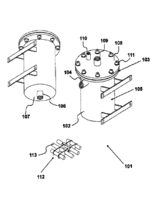
Figure 1
Apparatus 101 for use in the treatment of fluid in a fluid circuit of a
heating
or cooling system is shown in Figure 1. Fluid treatment apparatus 101
comprises
a vessel 102 that defines an open upper end 103, and a circulating fluid inlet
port
104, in this embodiment in a side wall 105 thereof, and a fluid outlet port
106, in
this embodiment, in the lower end 107 thereof. The open upper end 103 of the
vessel 102 is provided with a removable lid 108 defining a dosing port 109 and
an
air vent port 110. In this Figure, the removable lid 108 is shown secured to
the
vessel 102. Any suitable fixing may be used to releasably secure the removable
lid 108 to the vessel 102. In this illustrated embodiment, a plurality of
mechanical
fixings 111 is provided for this purpose.
Apparatus 101 further comprises a permanent magnet collector 112 for
collecting magnetic particles on an external collection surface 113 thereof.
The
permanent magnet collector 112 is removably locatable within the vessel 102.
As will be described in further detail, the apparatus 101 is usable for dosing
circulating fluid of a sealed heating or cooling system, and is advantageously
additionally usable between dosing events as a filter for the circulating
fluid of a
sealed heating or cooling system. The apparatus 101 thus provides the dosing
functionality of a known dosing pot and beneficially provides further
functionality.
CA 02903939 2015-09-03
WO 2014/135837 PCT/GB2014/000084
-5-
Fiaure 2
Figure 2 shows the apparatus 101 installed for use in the treatment of fluid
in a fluid circuit of a heating or cooling system.
In a method of installing the apparatus, the circulating fluid inlet port 104
is
, connected to a circulating fluid inflow conduit 201 via an associated
isolation
valve 202. The fluid outflow port 106 is connected to a circulating fluid
return
conduit 203 via an associated second isolation valve 204, and is connected to
a
drain conduit 205 via an associated isolation valve 206. The permanent magnet
collector 112 is located within the vessel 102. In this Figure, the permanent
magnet collector 112 is shown resting upon the internal floor of the vessel
102.
As shown in this Figure, the dosing port 109 is provided with a non-return
valve 207, the purpose of which will be discussed below, and an associated
third
isolation valve 208 upstream of the non-return valve 207. The air vent port
110 is
provided with an automatic air vent 209, the purpose of which will also be
discussed below.
The installed apparatus 101 is usable for dosing the circulaling fluid of the
system as follows. The vessel 102 is isolated from the fluid circi. it by
means of
the circulating fluid inlet port 104 and fluid outflow port 106 isolation
valves 202,
204, 206 being closed. If required, to drain the vessel 102, the fluid outflow
port
106 isolation valve 206 is opened to allow fluid within the vessel 102 to
leave
through the drain conduit 205; the drain conduit 205 is subsequently closed by
returning the fluid outflow port 106 isolation valve 206 to the closed
position.
With the dosing port 109 isolation valve 208 open, a fluid treatment additive
is
then introduced into the vessel 102, via the non-return valve 207; the dosing
port
109 isolation valve 208 is then subsequently closed. The circulating fluid
inlet
-port 104 isolation valve 202 and the fluid outflow port 106 isolation valve
204 are
then opened, to allow circulating fluid to flow through the vessel 102, from
the
inflow conduit 201 to the return flow conduit 203, to mix with the additive.
Therefore, in a method of treating fluid in a fluid circuit of a heating or
cooling system, the vessel is drained, a fluid treatment additive is
introduced into
CA 02903939 2015-09-03
WO 2014/135837 PCT/GB2014/000084
-6-
the vessel and circulating fluid is then subsequently allowed to flow through
the
vessel.
The installed apparatus 101 is usable for filtering the circulating fluid of
the
system as follows. The permanent magnet collector 112 is located within the
vessel 102. The fluid outflow port 106 isolation valve 206 is closed, to close
the
drain conduit 205, and the fluid outflow port 106 isolation valve 204 and
circulating fluid inlet port 104 isolation valve 202 are both opened, to allow
circulating fluid to flow through the vessel 102, from the inflow conduit 201
to the
.return flow conduit 203. The circulating fluid flowing through the vessel 102
flows
by the permanent magnet collector 112, which attracts any magnetic particles
within the circulating fluid onto the external collection surface 113 thereof.
In this
way the permanent magnet collector acts as a filter, for magnetic particles.
To
remove collected magnetic particles from permanent magnet collector 112, the
vessel 102 is isolated from the fluid circuit by means of the circulating
fluid inlet
port 104 and fluid outflow port 106 isolation valves 202, 204, 206 being
closed. If
required, to drain the vessel 102, the fluid outflow port 106 isolation valve
206 is
opened to allow fluid within the vessel 102 to leave through the drain conduit
205;
the drain conduit 205 is subsequently closed by returning the fluid outflow
port
.106 isolation valve 206 to the closed position. The removable lid 108 of the
vessel 102 is removed, to open the vessel 102, and the permanent magnet
collector 112 is removed from within the vessel 102, through the open end 103
of
the vessel 102. With the permanent magnet collector 112 removed from the
vessel, collected magnetic particles may be removed from the external
collection
surface 113 thereof; the cleared permanent magnet collector 112 is then placed
back into the vessel 102. The circulating fluid inlet port 104 isolation valve
202
and the fluid outflow port 106 isolation valve 204 are then opened, to allow
circulating fluid to flow through the vessel 102 again.
Therefore, in a method of treating fluid in a fluid circuit of a heating or
cooling system, the permanent magnet collector is removed from within the
vessel, magnetic material is removed from the external collection surface
thereof,
and the permanent magnet collector is subsequently replaced witl-in the
vessel.
CA 02903939 2015-09-03
WO 2014/135837 PCT/GB2014/000084
-7-
It is thus to be appreciated that the apparatus 101 is suitable for dosing,
and
also filtering, of circulating fluid of a sealed heating or cooling system.
The
'apparatus is suitable for dosing and filtering of circulating water of a
heating or
cooling system.
The non-return valve 207 of the dosing port 109 provides a safety feature.
The non-return valve 207 acts to prevent fluid from exiting the vessel 102
through
the dosing port 109, to avoid potential harm to an operative in attendance. At
the
time of a dosing event, the non-return valve 207 acts to prevent hazardous
exit of
fluid treatment additive that has been introduced into the vessel 102. As
described above, circulating fluid is allowed to flow through the vessel 102
between dosing events. In the event that the dosing port 109 isolation valve
208
is opened while circulating fluid is flowing through the vessel 102, under
pressure,
the non-return valve 207 acts to prevent hazardous exit of circulating fluid
from
the vessel 102. The non-return valve 207 thus serves to prevent undesired
splash-back or spurting of fluid out from within the vessel 102 that may cause
an
injury, such as an eye injury, to an operative in the vicinity thereof.
The automatic air vent 209 of the air vent port 110 functions to remove
excess air, and is beneficially operational during a dosing event, when an
operative is in attendance, and also while circulating fluid is flowing
through the
vessel 102, such as between dosing events when an operative may not be in
attendance.
Figure 3,
In Figure 3, the permanent magnet collector 112 is located within the vessel
102 of the apparatus 101.
In this illustrated embodiment, the vessel 102 is provided with at least one
bracket 301, for use in securing the vessel to a suitable support surface,
typically
a wall. Any suitable fixing may be used with the bracket 301.
The dimensions and shape of the vessel, and the ports, may vary between
applications, and may vary depending on the specific heating or cooling system
which with it is to be used. The capacity of the vessel determines the number
of
CA 02903939 2015-09-03
WO 2014/135837 PCT/GB2014/000084
-8-
times that it will need to be filled during a dosing event to achieve the
correct
concentration of fluid treatment additive introduced into the circulating
fluid of the
heating or cooling system. The required volume of fluid treatment additive to
be
added, such as a chemical inhibitor, will vary according to the specific
additive
being used, the concentration of additive in the circulating fluid to be
obtained
.and the specific size of the heating or cooling system.
As shown in this Figure, the vessel 102 has a circular cross-sectional
shape. The vessel may be fabricated from any suitable material or combination
of materials. In this illustrated embodiment, the vessel is fabricated from
stainless steel, and is uncoated, at least internally.
Figure 4
Figure 4 shows the permanent magnet collector 112 in further detail. The
permanent magnet collector 112 comprises a plurality of tubular housings, each
housing a permanent magnet, such as tubular housing 401 housing permanent
magnet 402.
Preferably, and in this embodiment, at least one end of each of the tubular
housings is provided with a removable cover, such as cover 403 of the end 404
of tubular-housing 401, to allow the selective removal of the pernanent magnet
housed therein. In this embodiment also, the external collection surface 405
of
each of the tubular housings, is a non-magnetic surface. This beneficially
provides for magnetic particles collected on the external collection surface
of a
tubular housing to be removed by the process of removing the permanent
magnet from within the tubular housing and allowing the magnetic particles to
drop from the external collection surface of the tubular housing; the
permanent
magnet is then subsequently replaced inside the tubular housing.
Alternatively,
and in an embodiment in which the tubular housing is not provided with a means
of allowing removal of the permanent magnet therein, the magnetic particles
may
be wiped from the external collection surface.
As shown, the tubular housings are relatively arranged ir the form of a
grate. In this illustrated embodiment, the grate arrangement comprises a pair
of
CA 02903939 2015-09-03
WO 2014/135837 PCT/GB2014/000084
-9-
longer tubular housings disposed between shorter tubular housings, to
complement a circular cross-sectional shape of a vessel with which the
permanent magnet collector is to be used. The tubular housings are connected
by at least one connector 406. In this example, the underside of the permanent
magnet collector 112 is substantially planar.
Preferably, the permanent magnet collector 112 comprises a handle 406, to
facilitate manual handling of the permanent magnet collector 102 during
placement within a vessel and removal from a vessel.
It is to be appreciated that any suitable number of tubular housings
containing a permanent magnet may be used, in any suitable arrangement. The
dimensions and shape of tubular housings may also vary between applications.
Components of the permanent magnet collector may be fabricated from any
suitable material or combination of materials. In this illustrated embodiment,
each of the tubular housings, each connector and the handle are each
fabricated
from stainless steel.
Figure 5
As shown in Figure 5, the fluid treatment apparatus 101 may comprise
additional components for use therewith.
' The apparatus 101 may comprise a filter 501 that is removably locatable
within the vessel 102. The filter 501 is provided for filtering non-magnetic
particles from the circulating fluid of a heating or cooling system. The
filter may
comprise any suitable filtration media and will typically have a fluid filter
rating in
the range 5-100 micrometres. According to this illustrated embodiment, the
filter
501 has a sealed top 502 and defines a hollow central core 503. The filter 501
is
substantially circular, to complement a circular cross-sectional shape of a
vessel
with which the filter is to be used.
The apparatus 101 also further comprise a baffle plate 504 removably
locatable within the vessel 102. The baffle plate 504 is substantially
circular, to
.complement a circular cross-sectional shape of a vessel with which the baffle
plate is to be used. The baffle plate 504 has a solid central portion 505 with
an
CA 02903939 2015-09-03
WO 2014/135837 PCT/GB2014/000084
-10-
outer edge 505 that is profiled to provide cut-away portions, such as cut-away
portion 506. In this embodiment, the baffle plate is fabricated from stainless
steel.
The baffle plate may however be fabricated from any suitable material or
combination of materials.
The apparatus 101 may also further comprise a dosing funnel 507,
releasably connectable relative to the dosing port 109 of the vessel 102. The
dosing funnel may have any suitable shape and dimensions, and may be
fabricated from any suitable material or combination of materials. In this
embodiment, the dosing funnel is fabricated from stainless steel.
Figure 6
Figure 6 shows the permanent magnet collector 112, filter 501 and baffle
plate 504 located within the vessel 102 of the apparatus 101.
In a method of installing the apparatus, the filter 501 is placed into the
vessel 102 first, the baffle plate 504 is then placed into the vessel 102 upon
the
filter 501, and then the permanent magnet collector 112 is placed into the
vessel
102 upon the baffle plate 504. Thus, as shown in this Figure, the permanent
magnet collector, filter and baffle plate are located within the vessel such
that the
filter is lowermost, the permanent magnet collector is uppermost and the
baffle
plate is located between the filter and the permanent magnet collector, such
that
circulating fluid flowing through the vessel passes the permanent magnet
collector and subsequently passes through the filter. Thus, during filtering,
the
-permanent magnet collector collects magnetic particles (such as magnetite,
iron-
oxide, metal debris) and the filter collects other particles (such as calcium
deposits). The filter may be removed from the vessel and cleaned or replaced,
as appropriate, by a similar process as that described for the removal,
cleaning
and replacement of the permanent magnet collector as previously described.
The weight of the baffle plate and permanent magnet collector upon the
filter also serve to stabilise the filter in use.
It is thus to be appreciated that the apparatus 101 is suitable for dosing,
and
advantageously also filtering, of circulating fluid of a sealed heating or
cooling
CA 02903939 2015-09-03
WO 2014/135837 PCT/GB2014/000084
-11-
system. The apparatus 101 may provide a single-stage filter function, provided
by the permanent magnet collector, as described with reference to Figure 3, or
may provide a two-stage filter function, provided by the permanent magnet
collector and the filter, as described with reference to Figure 6.
The fluid treatment apparatus as described herein beneficially provides a
vessel that can be used as a dosing pot for commercial heating and cooling
systems, and that can beneficially be used as a filter for the circulating
fluid of the
system between dosing events. The apparatus as described herein may thus be
'normally open' to the system fluid flow.
Figure 7
Figure 7 shows an alternative baffle plate 701. The baffle plate 701 is
removably locatable within the vessel of a fluid treatment apparatus. The
baffle
plate 701 is substantially circular, to complement a circular cross-sectional
shape
of a vessel with which the baffle plate is to be used.
The baffle plate 701 has a solid central portion 702 and defines a plurality
of
apertures therein, such as aperture 703, spaced inwardly from the outer edge
704 thereof. In this example, the baffle plate 701 defines sixteen equally
sized
circular apertures, spaced equidistantly around a ring 705. It is to be
appreciated
however that the baffle plate may define a different number of apertures,
which
may be equally or differently sized, of any suitable shape and in any suitable
arrangement.
In this embodiment, the baffle plate 701 comprises a plurality of locator
legs,
such as leg 706, extending from the underside 707 thereof. In this example,
the
baffle plate 701 defines four locator legs of equal length, spaced
equidistantly
around a ring 708. It is to be appreciated however that the baffle plate may
comprise a different number of locator legs, in any suitable arrangement.
The baffle plate 701 further comprises a handle 709 on the upper side 710
thereof. In this example, the handle 709 is a lifting eye, located
substantially
centrally of the baffle plate 701. The handle 709 may take any suitable form
and
arrangement.
CA 02903939 2015-09-03
WO 2014/135837 PCT/GB2014/000084
-12-
An alternative filter 711 is also shown in Figure 7. The filter 711 is
removably locatable within the vessel of a fluid treatment apparatus. The
filter
711 is substantially circular, to complement a circular cross-sectional shape
of a
vessel with which the filter is to be used. The filter 711 is a cartridge
filter having
a sealed top 712 and defining a hollow central core 713 that is surrounded by
filtration media 714.
In this embodiment, the filter 711 has a location spigot 715 at the lower end
716 thereof. The location spigot 715 is dimensioned to be located within the
fluid
outlet port at the lower end of a vessel with which the filter is to be used.
This
feature serves to stabilise the filter during installation and when in use.
In this embodiment, the upper end 717 of the filter 711 defines location
openings, such as opening 718, for receiving the locator legs 706 of the
baffle
plate 701 therein. The number and arrangement of location openings in the
upper end 717 of the filter 711 complements the number and arrangement of
locator legs 706 of the baffle plate 701.
The filter may comprise any suitable filtration media and will typically have
a
fluid filter rating in the range 5-100pm. The filter may be a 100pm, 50pm or
20pm filter.
= Figure 8
Figure 8 shows the permanent magnet collector 112, filter 711 and baffle
plate 701 located within the vessel 102 of the apparatus 101.
In a method of installing the apparatus, the filter 711 is placed into the
vessel 102 first, such that the spigot 715 is located within the fluid outlet
port 106
of the vessel 102. The baffle plate 701 is then placed into the vessel 102
upon
the filter 711, such that the locator legs 706 of the baffle plate 701 are
located
within the location openings 718. The permanent magnet collector 112 is then
placed into the vessel 102 upon the baffle plate 701. In accordance with the
specific examples, the handle 709 extends into the permanent magnet collector
.112.
CA 02903939 2015-09-03
WO 2014/135837 PCT/GB2014/000084
-13-
Thus, as shown in this Figure, the permanent magnet collector, filter and
baffle plate are arranged within the vessel such that circulating fluid
flowing
.through the vessel passes the permanent magnet collector and subsequently
passes, along a path directed by the baffle plate, into the filtration media
of the
filter and out through the hollow central core of the filter and into the
fluid outlet
port of the vessel.
The illustrated arrangement provides a combination dosing and filtering unit.
A method of use of the fluid treatment apparatus described herein with
circulating water of a sealed heating or cooling system will now be described.
The fluid treatment apparatus is installed, and the vessel is used to dose the
system water. The permanent magnet collector only is then located within the
vessel, to purge the system water of metallic debris. After a period of time,
for
example 2 weeks, the permanent magnet collector is removed, and cleaned.
Then the permanent magnet collector and a 100pm filter are located within the
vessel. The filter and permanent magnet collector are checked at regular
intervals, for example each week, for contamination and cleanliness. When the
100pm filter has been used, this is replaced with a 50pm filter. The filter
and
permanent magnet collector are again checked at regular intervals, for example
each week, for contamination and cleanliness. When the 50pm filter has been
used, this is replaced with a 20pm filter. The incremental decrease in the
filter
size serves to polish the system water to restore cleanliness of the system
water
towards original cleanliness. The permanent magnet collector and filter are
subsequently checked at regular maintenance intervals, and the permanent
'magnet collector cleaned and the filter replaced as required.
Figure 9
Figure 9 shows the permanent magnet collector 112, and baffle plate 701
located within the vessel 102 of the apparatus 101.
The baffle plate 701 is shown located within the vessel 102 such that the
locator legs 706 thereof rest upon the internal floor of the vessel 102, and
the
permanent magnet collector 112 is shown located upon the baffle plate 701.
CA 02903939 2015-09-03
WO 2014/135837 PCT/GB2014/000084
-14-
In the shown arrangement, the permanent magnet collector 112 is raised
above the internal floor of the vessel 102 by the baffle plate 701. The baffle
plate
701 acts to reduce the flow rate at which circulating system fluid exits the
vessel
102, through the fluid outlet port 106, such that a low-flow region is formed
above
the baffle plate 701 in which the permanent magnet collector 112 is supported.
The baffle plate 701 directs the circulating system fluid to exit the vessel
102
through the ring of apertures 703 defined therein, along exit flow paths near
the
internal walling of the vessel 102. With the baffle plate 701 and permanent
magnet collector 112 arranged within the vessel 102 as shown in this Figure,
the
contact time of the circulating system fluid with the permanent magnet
collector
112 in increased, across substantially whole of the area of the external
collection
surface 113. This serves to maximise the efficiency of the permanent magnet
collector 112.
Figure 10
The fluid treatment apparatus 101 may have further and/or alternative
.features to those previously described herein.
As shown in this Figure, the air vent port 110 is provided with a manually
operable air vent 1001, upstream of the automatic air vent 209. In a method of
dosing the circulating system fluid, the manually operable air vent 1001 is
opened
before a fluid treatment additive is introduced into the vessel 102 through
the
dosing port 109. The opening of the manually operable air vent 1001 acts to
allow for faster introduction of fluid treatment additive into the vessel 102
and also
acts to prevent introduced fluid treatment additive from entering the
automatic air
vent 209.
As shown in Figure 10, the vessel 102 may be provided with at least one
.support leg 1002, for use in mounting the vessel upon a suitable support
surface,
such as a floor. A support leg may be provided in addition to, or as an
alternative
to, at least one bracket 301. One or more support legs may be provided for use
with larger and heavier vessels, which require a greater degree of support
than
smaller and lighter vessels.
CA 02903939 2015-09-03
WO 2014/135837 PCT/GB2014/000084
-15-
The fluid treatment apparatus described herein may thus be used to provide
an initial single-stage filtration process (permanent magnet collector only)
and
then a double-stage filtration process (permanent magnet collector and
filter),
which can be modified over time to remove smaller and smaller sized
contaminants from the circulating system fluid.
Advantages of the fluid treatment apparatus and method of the present
invention include: dual dosing and filtering functionality, convenient
installation,
operation and maintenance, improved system circulation, improved efficiency of
system, reduced risk of system failure, increased working life of system
components, reduced maintenance costs.