Note: Descriptions are shown in the official language in which they were submitted.
REPLACEMENT SHEET
1
PRESSURE VESSEL LID QUICK CLOSURE SYSTEM
BACKGROUND OF THE INVENTION
[0001] The present invention is a manually operated lid closure system for
industrial
vessels which operate under high negative or positive pressure. Typical
closure devices for
vessels are described in many Canadian patents including Nos. 430,628,
689,269, 704,121,
723,471, 782,897, 788,809, 867,622, 878,310, 943,879, 960,379, 2,093,852,
2,109,846,
2,109,847, 2,121,777, and 2,393,693. These designs are based on using screws,
levers,
toggles, tapered tongues, clamps, or hydraulic cylinders to exert tension on
the mechanism that
induces a clamping force to seal the lid of the pressure vessel to its shell.
[0002] These earlier designs suffer from several drawbacks. They typically
involve
configurations of complex parts for the closure mechanism. Existing component
features
require complicated and costly fabrication techniques. Most of the designs are
not scalable for
vessels of widely varying size. Finally, the operation of existing closure
systems is time-
consuming, physically taxing, or require special tools to perform.
[0003] The present invention is a unique mechanism which enables the
application of
sufficient mechanical restraint to contain high-pressure fluids with a
manually operated cam
device. No tools are necessary to quickly open or close any vessel equipped
with this device.
CA 2904063 2017-06-27
CA 02904063 2015-09-16
=
2
=
SUMMARY OF THE INVENTION
[004] The present invention provides for the rapid manual opening and closing
of the
lid of an industrial pressure vessel without the need for any tools. A
pressure vessel is
equipped with two circular mating rings welded to the adjacent rims of the
vessel shell and
the vessel lid respectively. The vessel shell ring bears a groove within which
sits a
compressible 0-ring. These rings are tapered at an angle to accommodate
external
clamping elements with matching taper angles. Each clamping element is a semi-
circular
assembly of enclosing rings or a plurality of enclosing blocks which is drawn
radially
towards the center of the vessel, forcing the shell and lid rings together
along mating
inclines until the lid and shell rings are in full contact around the
perimeter of the vessel.
[005] The mechanism which applies tension to draw the clamping elements
radially
inward relies on a pair of cam plates. The cam plates;
[006] i) are arranged parallel to each other.
[007] ii) are located on opposite sides of the vessel.
[008] iii) share a common pivot axis in the plane of the mating faces of the
aforementioned lid and vessel rings, said horizontal pivot axis also
intersecting the vertical central axis of the vessel shell itself.
[009] iv) rotate in concert in parallel vertical planes by manual force
applied to a lever
fabricated from round rod which wraps around the vessel body and is
connected to both plates.
[010] Pins mounted in the horizontal plane in devises at the ends of each of
two
semi-circular clamping elements maintain contact with cam surfaces in curved
slots in the
cam plates. While the cam plates pivot about their centers in the vertical
plane, the cam
surfaces in the plates draw the aforementioned pins together with increasing
mechanical
advantage as the pins approach their minimum separation distance. The clamping
elements are constrained to move radially in a horizontal plane by guide
plates within
which the devises slide. Integral with the semi-circular external clamping
elements, the
pins cause the clamping elements to engage in a balanced fashion with the lid
and shell
rings and apply a closing force through the action of sliding tapers.
[011] The cam elements may be variably configured to apply increasing force
gradually to overcome compression resistance of the 0-ring in its groove in
the shell ring
until the lid and shell rings are in full contact. Once in a fully closed
position, the clamping
CA 02904063 2015-09-16
3
mechanism is also capable of withstanding the forces of vessel pressure which
tend to
separate the lid from the vessel shell.
[012] When it is necessary to open the vessel lid, the rotation of the cam
plates is
reversed, the pins mounted in the clamping element clevises separate, and the
clamping
elements slide away from the mating rings on the lid and shell until
sufficient clearance is
obtained to allow the lid to be lifted without interference. The procedures
for both closing
and opening the vessel lid take only moments using average human hand effort.
[013] Three different safety features ensure that the cam-operated closure
mechanism cannot be activated to release vessel pressure before they are
intentionally
set in the released position:
[014] i) One safety feature is a design characteristic of the cam surfaces in
the cam
plate. As the cam plate is rotated to draw the clamping element pins
together, the last few degrees of rotation occur with the pins sliding on cam
surfaces that are radially concentric with the pivot axis of the cam plate.
This ensures that there is no resolved force of the clamping elements under
tension that would tend to cause the pins to separate even if the rotation of
the cam plate is unconstrained.
[015] ii) A second safety feature is a lever and associated linkage connected
to a
pressure relief valve typically mounted at the apex of the lid of the pressure
vessel. When the vessel is under pressure, the aforementioned lever rests
in a slot in the cam plate body, preventing rotation of the cam plate. The
lever is positively retained in the cam plate slot with a spring-loaded
retractable pin. Until the aforementioned pin is retracted, the lever may not
be disengaged. Disengagement of the lever drives the associated linkage to
cause the pressure relief valve to open, thereby ensuring release of vessel
pressure prior to operation of the cam mechanism for opening the vessel lid.
[016] iii) A third safety feature is a retaining bracket mounted on the side
of the
vessel shell. When the vessel lid is in the closed position and the clamping
elements are engaged with the lid and shell rings, the aforementioned lever
which enables hand-operated rotation of the cam plates rests in a slot in the
retaining bracket. The lever is retained therein by a pin which must be
removed manually before the closure mechanism can be actuated.
CA 02904063 2015-09-16
4
[017] The invention provides for a very rapid opening and closing of a
pressure
vessel for access to its internal features without the need for mechanical
tools or auxiliary
systems such as hydraulic or pneumatic machinery.
BRIEF DESCRIPTION OF THE DRAWINGS
FIG. 1 is a perspective view of a typical closed-lid vessel equipped with the
cam-
actuated closure mechanism and a detail view of one of the safety lock
features.
FIG. 2 is a section view of the clamping arrangement which mates the lid ring
with the
shell ring of a pressure vessel in a closed state.
FIG. 3 is a perspective view of a typical open-lid vessel equipped with the
cam-
actuated closure mechanism.
FIG. 4 is a section view of the clamping component retracted from engagement
with
the lid and shell rings, showing only the shell ring as the lid ring is
pivoted up and out of
sight.
FIG. 5 is a side view of a typical closed-lid vessel with annotation
identifying key
elements of the vessel and closure mechanism.
FIG. 6 is a side view of a typical open-lid vessel with annotation identifying
key
elements of the vessel and closure mechanism.
FIG. 7 is a perspective view of the closure mechanism and clamping ring
subassemblies in lid-closed position.
FIG. 8 is a perspective view of the closure mechanism and clamping ring
subassemblies in lid-open position.
FIG. 9 is a perspective exploded view of the components of the cam-actuated
closure
system.
FIG. 10 is a perspective view of the arrangement of two continuous clamping
rings
which engage with the lid and shell lip rings.
FIG. 11 is a perspective exploded view of the components of one of the
continuous
clamping rings illustrated in FIG. 10.
FIG. 12 is a perspective view of the arrangement of two clamping rings with a
plurality
of machined blocks which engage with the lid and shell lip rings.
FIG. 13 is a perspective exploded view of the components of one of the
clamping rings
with a plurality of machine blocks illustrated in FIG. 12.
CA 02904063 2015-09-16
FIG. 14 is a side and top view with section detail of the closure mechanism
fully open
to enable the release of shell and lid clamped rings with the lip ring pivoted
out of range.
FIG. 15 is a side and top view with section detail of the closure mechanism
halfway
actuated to full closure of shell and lid clamped rings.
FIG. 16 is a side and top view with section detail of the closure mechanism
illustrating
the rotational point at which protection is now available from unintended
release of tension
to vessel pressure.
FIG. 17 is a side and top view with section detail of the closure mechanism in
the fully
closed position.
FIG. 18 is a 3-view depiction of a typical cam plate integral to the quick-
closure
mechanism.
FIG. 19 is a second possible configuration of the cam plate illustrating both
dual and
single cam action for a specific rotation angle with variable closed and open
separation
distances for two clamping ring subassemblies.
FIG. 20 is a third possible configuration of the cam plate illustrating both
dual and
single cam action for another specific rotation angle with variable closed and
open
separation distances for two clamping ring subassemblies.
FIG. 21 is a perspective view of the primary safety lock system with details
showing
the vessel pressure release valve in closed position and the safety lock lever
engaged
with the closure system cam plate.
FIG. 22 is a perspective view of the primary safety lock system with details
showing
the vessel pressure release valve in open position and the safety lock lever
disengaged
with the closure system cam plate.
DETAILED DESCRIPTION OF THE INVENTION
[018] The following is a listing of reference numbers corresponding to a
particular
element referred to herein:
1 Clamping Channel
2 Shell Clamp Ring
3 Shell Wall
4 Lid Clamp Ring
5 Lid Wall
6a 0-Ring Uncompressed
CA 02904063 2015-09-16
6
6b 0-Ring Compressed
7 Clamp Ring Welds
8 Lid Lift Mechanism
9 Primary Safety Lock Mechanism
Secondary Safety Lock Mechanism
11 Tensioning Cam Plate
12a Cam Pin Standard Clevis
12b Cam Pin Adjustment Clevis
13 Cam Pin
14a Cam Pin Clevis Fixed-Pivot Guide Plate
14b Cam Pin Clevis Floating-Pivot Guide Plate
Tensioning Lever Rod
16 Tension Adjustment Mechanism
17 Cam Pivot Pin
18a Primary Safety Lock Release Pin Closed
18b Primary Safety Lock Release Pin Open
19 Cam Pin Clevis Guide Plate Shell Mounting Bracket
Quick Closure Mechanism
21 Tension Adjustment Screw Mounting Lug
22 Tension Adjustment Screw
23 Tension Adjustment Nut
24 Cam Pin Adjustment Clevis Slide Pin
Cam Pin Restraint Fastener
26 Clamping Block Ring Plate
27 Clamping Block
28 Clamping Block Mounting Screw
29 Clevis or Lug Weld Bead
Adjustable Clamp Ring Subassembly
31 Standard Clamp Ring Subassembly
32 Clamping Channel WRT Shell and Lid Rings Clearance
33 Typical Taper Angle for Clamping Mated Components
34a Cam Pin Clevis Guide Plate Fixed-Pivot Hole
34b Cam Pin Clevis Guide Plate Floating-Pivot Slot
CA 02904063 2015-09-16
7
35 Cam Pin Clevis Guide Adjustable Mounting Holes
36 Clamping Channel Forward Support Bracket
37 Lid Lift Mechanism Support Bracket
38 Cam Pin Adjustment Clevis Slide Pin Slot
39 Clamping Channel Flat Surface for Cam Pin Clevis Mounting
40 Adjustable Clamp Block Subassembly
41 Standard Clamp Block Subassembly
42 Shell Assembly
43 Lid Assembly
50 Cam Plate Pin Guide
51 Cam Plate Pivot Hole
52 Cam Plate Safety Lock Lever Groove
53 Cam Plate Safety Lock Spring Pin Hole
54 Cam Plate Tensioning Lever Rod Seat
55 Cam Closed Position Safety Range Angle
56 Primary Safety Lock Lever
57 Primary Safety Lock Lever Mounting Bracket
58 Primary Safety Lock Linkage Arm
59 Safety Valve
60a Safety Valve Lever Closed
60b Safety Valve Lever Open
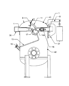
[019] With reference to FIG. 1, a pressurized vessel is comprised of a shell
assembly
42 and a lid assembly 43 wherein the vessel is represented as closed. Under
normal
operating conditions the vessel must be opened and closed repeatedly to access
its
internal components where the lid lift mechanism 8 counterbalances the weight
of the lid
during said procedures. To contain vessel pressure safely during operation, a
quick
closure mechanism 20 is provided to ensure that the lid assembly 43 remains
firmly
sealed to the shell assembly 42 by the application of tension along the rim
perimeter. The
said quick closure mechanism 20 is represented as in a fully tensioned state.
Also
illustrated in FIG. 1 are two different safety lock mechanisms; a primary
mechanism 9
which associates the release of the quick closure mechanism 20 with a pressure
relief
valve, and a secondary mechanism 10 which prevents the tensioning mechanism
from
activation until a pin is removed as shown in Detail 1.
CA 02904063 2015-09-16
8
[020] The nature of the seal maintained between the shell assembly 42 and the
lid
assembly 43 is illustrated in FIG. 2 which represents a section through the
rim of the
vessel at the plane of the seal between shell and lid. The vessel shell 3 is
equipped with
a circular clamp ring 2 attached to the shell with weld beads 7. The vessel
lid 5 is
equipped with a circular lid clamp ring 4 attached to the lid also with weld
beads 7. Radial
tension is exerted by action of the quick closure mechanism 20 to draw two
clamping
channels 1 in a horizontal plane toward the center of the vessel. With force
applied along
the inclines 33 representing a typical taper angle for clamping mated
components, the lid
ring 4 is brought into firm contact with the shell ring 2, compressing the 0-
ring 6b to act as
a pressure seal.
[021] FIG. 3 presents the aforementioned pressure vessel in the fully open
state
wherein the lid assembly 43 has been rotated upward about a pivot point
incorporated in
the aforementioned lid lift mechanism 8. In this state the vessel internal
components are
accessible. The quick closure mechanism 20 is represented as in fully relaxed
state
wherein the clamping ring 1 is now displaced radially outward to enable
separation of the
lid assembly 43 from the shell assembly 42. FIG. 4 represents a section
through the rim
of the vessel at the horizontal plane of the top surface of the shell clamping
ring 2. In this
instance, the clamping channel 1 is withdrawn from contact with the shell
clamping ring 2
and the lid clamping ring 4 such that the lid assembly 43 may be pivoted up
into the
vessel-open state. The same illustration shows that the 0-ring 6a is now
uncompressed.
[022] FIG. 5 is a side view of the aforementioned pressurized vessel in the
closed
state. Key elements of the quick closure mechanism 20 are identified for
further
explanation of the function of the invention. The tensioning cam plate 11 may
be made to
rotate about the cam pivot pin 17 by application of manual force using a
tensioning lever
rod 15 if the primary and secondary safety lock mechanisms 9 and 10
respectively are
defeated. In this illustration, both clamping channels 1 are fully tensioned,
causing the
shell clamping ring 2 and the lid clamping ring 4 to be in full contact around
the perimeter
of the vessel.
[023] FIG. 6 is a side view of the aforementioned pressurized vessel in the
open
state. Primary and secondary safety lock mechanisms 9 and 10 respectively have
been
defeated to permit activation of the quick closure mechanism 20. In this case,
the
tensioning cam plate 11 has been rotated to its clockwise limit through
application of
manual force to the tensioning lever rod 15, causing both clamping channels 1
to
CA 02904063 2015-09-16
9
withdraw radially outward from contact with the shell clamping ring 2 and the
lid clamping
ring 4, allowing the lid assembly 43 to be pivoted upward. During movement
outward, the
clamping channel 1 at left is maintained in the horizontal plane by a clamping
ring forward
support bracket 36 and the clamping channel 1 at right is similarly guided by
a lid lift
mechanism support bracket 37. Also referenced is a cam pin clevis fixed-pivot
guide
plate 14a which ensures that the tensioned elements of both clamping channels
1 remain
in the horizontal plane throughout activation of the quick closure mechanism.
[024] FIG. 7 is a perspective view of the present invention isolated from the
aforementioned pressurized vessel, identifying key elements of the design. The
closure
mechanism is mounted on two brackets 19 which are in turn welded to the vessel
shell
wall 3. The closure mechanism 20 is illustrated in the tensioned state where
two
tensioning cam plates 11 are applying maximum closure force on two balanced
clamping
channels 1 with a manually operated tensioning lever rod 15 in the extreme
downward
position. Further attention is drawn to three cam pin standard clevises 12a
and one cam
pin adjustment clevis 12b, all of which are welded to the ends of the clamping
channels 1.
The devises incorporate cylindrical pins which ride on symmetrical cam
surfaces in the
aforementioned tensioning cam plates 11. The said clevises move horizontally,
constrained by the cam pin clevis fixed-pivot guide plate 14a and the cam pin
clevis
floating-pivot guide plate 14b. A
tension adjustment mechanism 16 is used to
accommodate manufacturing tolerances to enable assembly of the closure
mechanism
with precise control over final compression of the lid clamping ring 4 with
respect to shell
clamping ring 2 when the device is in the fully tensioned state.
[025] FIG. 8 is a perspective view of the present invention, isolated from the
aforementioned pressure vessel, in this case in the tension-free state. Now
the tensioning
cam plates 11 have been rotated clockwise to their fullest extent and the two
clamping
channels 1 have been withdrawn radially with sufficient displacement to allow
the lid
clamp ring 4 to disengage, thereby enabling opening of the vessel.
[026] FIG. 9 is an exploded perspective view of the quick closure mechanism
and
related elements. In the closed state, the system incorporates a shell
clamping ring 2 and
its 0-ring 6b mated with a lid clamping ring 4 in contact in the horizontal
plane, forced into
engagement by two clamping channels 1. When rotated about the axes of the cam
pivot
pins 17, the two tensioning cam plates 11 apply contracting force on the
perimeter of the
pressure vessel rim by cam action of curved slots which engage pins 13
embodied in
CA 02904063 2015-09-16
three cam pin standard clevises 12a and one cam pin adjustment clevis 12b. A
cam pin
clevis fixed-pivot guide plate 14a and a cam pin clevis floating-pivot guide
plate 14b
provide alignment of the two separate clamping channels 1 in the horizontal
plane during
contraction or expansion of the assembled mechanism.
[027] Machining and welding procedures employed to fabricate the quick closure
system typically result in dimensional variations in components. Again in
reference to
FIG. 9, two design features accommodate these variations;
[028] i) Two cam pin clevis guide plate shell mounting brackets 19 are welded
to the
pressure vessel shell 3. The said brackets are equipped with adjustable
mounting holes, or slots, which enable fastening of the two cam pin clevis
guide plates 14a and 14b at variable distances offset from the vessel shell.
[029] ii) The final assembly of the quick closure mechanism depends on
establishing
correct component displacements on the perimeter of the pressure vessel
using a tension adjustment screw 22 which threads into the cam pin
adjustment clevis 12b and passes through a tension adjustment screw
mounting lug 21. Three tension adjustment nuts 23 are turned as needed to
set the correct displacements for proper operation of the said quick closure
mechanism 20.
[030] The present invention provides for multiple configurations of rim
clamping
devices. Two such possibilities are illustrated as follows;
[031] i) Per FIG. 10, the active clamping action at the pressure vessel rim is
applied
by a semi-circular metal bar (clamping channel 1) where its internal faces
have been machined on a lathe to conform to the shapes of the mating shell
clamp ring 2 and the lid clamp ring 4 as depicted in FIG. 2. FIG. 10
illustrates the pairing of two such design elements, an adjustable clamp ring
subassembly 30 and a standard clamp ring subassembly 31, wherein the
said subassemblies are drawn together radially inward during activation of
the quick closure mechanism. Further detail regarding the manufacture of
the adjustable clamp ring subassembly 30 is illustrated in FIG. 11 which is
an exploded perspective view of the elements of the design. At one end of
the clamping channel 1 a cam pin standard clevis 12a is affixed to a
flattened surface with a weld bead 29. The cam pin 13 is mounted through
the holes of the said clevis and retained in place with a cam pin restraint
CA 02904063 2015-09-16
11
fastener 25. At the opposite end of the clamping channel 1 a tension
adjustment screw mounting lug 21 is affixed to the said clamping channel's
exterior cylindrical surface with a weld bead 29 at a suitable distance from
the adjacent said clamping channel end. The tension adjustment screw 22
passes through the hole in the aforementioned mounting lug and is fastened
to the cam pin adjustment clevis 12b which bears a mating internal thread.
The corresponding end of the clamping channel 1 bears a flat surface 39
and a slot 38 which is engaged by a cam pin adjustment clevis slide pin 24
which in turn is mounted in the said cam pin adjustment clevis 12b. The
said slide pin ensures continued proper alignment of the cam pin adjustment
clevis 12b during installation of the quick closure mechanism as the tension
adjustment nuts 23 are tightened to set appropriate closed device tension.
The cam pin 13 is mounted through the holes of the cam pin adjustment
clevis 12b and retained in place with the cam pin restraint fastener 25.
[032] ii) Per FIG. 12, the active clamping action at the pressure vessel rim
is applied
by a plurality of metal blocks 27 each of which has its internal faces
machined on a 3-axis CNC milling machine to conform to the shapes of the
mating shell clamp ring 2 and the lid clamp ring 4 as depicted in FIG. 2. The
said metal blocks are mounted on a clamping block ring plate 26 with
machined internal faces oriented radially inward. FIG. 12 illustrates the
pairing of two such design elements, an adjustable clamp block
subassembly 40 and a standard clamp block subassembly 41, wherein the
said subassemblies are drawn together radially inward during activation of
the quick closure mechanism. Further detail regarding the manufacture of
the adjustable clamp block subassembly 40 is illustrated in FIG. 13 which is
an exploded perspective view of the elements of the design. A clamping
block ring plate 26 is formed with flat segments arranged to mate with the
flat rear face of each of the appropriate number of the clamping blocks 27,
the number of which is variable depending on the requirements of pressure
vessel design. Each clamping block 27 is mounted to the clamping block
ring plate 26 with two countersunk screws 28 which are threaded into
tapped holes in the said ring plate. At one end of clamping block ring plate
26 a cam pin standard clevis 12a is affixed to the outer surface with a weld
CA 02904063 2015-09-16
12
bead 29. The cam pin 13 is mounted through the holes of the said clevis
and retained in place with a cam pin restraint fastener 25. At the opposite
end of the clamping block ring plate 26 a tension adjustment screw
mounting lug 21 is affixed to the said ring plate's exterior surface with a
weld
bead 29 at a suitable distance from the adjacent said ring plate end. A
tension adjustment screw 22 passes through the hole in the aforementioned
mounting lug and is fastened to the cam pin adjustment clevis 12b which
bears a mating internal thread. The corresponding end of the clamping
block ring plate 26 bears a flat surface 39 and a slot 38 which is engaged by
the cam pin adjustment clevis slide pin 24 which in turn is mounted in the
said cam pin adjustment clevis 12b. The said slide pin ensures continued
proper alignment of the cam pin adjustment clevis 12b during installation of
the quick closure mechanism 20 as the tension adjustment nuts 23 are
tightened to set appropriate closed-device tension. A cam pin 13 is
mounted through the holes of the cam pin adjustment clevis 12b and
retained in place with a cam pin restraint fastener 25.
[033] In reference to FIGS. 14, 15, 16, and 17, actuation of the quick closure
mechanism 20 is hereby described in detail. In each Side View, described
rotation is
about the cam pivot pin 17. The foremost legs of the cam pin standard clevis
12a and the
cam pin adjustment clevis 12b are cut away for clarity;
[034] i) FIG. 14 presents top and side views wherein the said closure
mechanism 20
is in the fully relaxed state. The Side View shows the tensioning cam plate
11 with two cam pins 13 residing at the extreme range of rotation within the
cam plate cam guides 50.
Detail 14 illustrates clamping channel 1
withdrawn radially away from the vessel center and shell clamping ring 2 is
exposed with the 0-ring 6a resting in its groove in an uncompressed state.
The lid clamping ring 4 is not shown as it is rotated up and out of view as
part of the lid assembly 43 during opening of the vessel. The Top View
shows clamping channel 1 clearance 32 with respect to the shell clamp ring
2 and the lid clamp ring 4, enabling unobstructed lifting of the lid assembly
43.
[035] ii) FIG. 15 presents top and side views wherein the tensioning cam plate
11 of
the said closure mechanism 20 has rotated through half its possible range
CA 02904063 2015-09-16
13
under the influence of manual effort applied to the tensioning lever rod 15.
As the said plate rotates in a counter clockwise direction, two cam pins 13
slide along surfaces in the cam plate pin guides 50 and with symmetric
arrangement of the said pin guides, both clamping channels 1 approach
radially toward the center of the pressure vessel at matching rates of
displacement. Detail
15 shows a clamping channel 1 approaching
engagement in the horizontal plane with the mated shell clamp ring 2 and lid
clamp ring 4. The Top View illustrates how the clamping channel 1 now
overlaps the lid clamp ring 4, obstructing lifting of the vessel lid assembly
43.
[036] iii) FIG. 16 presents top and side views wherein the tensioning cam
plate 11
has been rotated to the point of closest approach of the ends of the two
clamping channels 1. It is to be noted that the cam pins 13 are not yet at the
extent of their range in the cam plate pin guides 50. This design
characteristic of the present invention represents a significant safety
condition wherein there is a continuing range of rotation of the tensioning
cam plate 11 where no resolved force exists on the cam surfaces tending to
permit the quick closure mechanism 20 to relax tension on the clamping
channels 1. Detail 16 illustrates that full closure has been achieved with a
clamping channel 1 now engaged with the shell clamp ring 2 and the lid
clamp ring 4 and the 0-Ring 6b is fully compressed to maintain an effective
vessel pressure.
[037] iv) FIG. 17 presents top and side views wherein the tensioning cam plate
11 is
now fully rotated counter clockwise. The cam pins 13 are positioned at the
extreme range of rotation along the cam surfaces of the cam plate pin
guides 50. Any degree of rotation between the fully rotated state and the
previous state illustrated in FIG. 16 maintains full tension on the adjustable
clamp ring assembly 30 and the standard clamp ring assembly 31.
Similarly, in the application of the design variation as depicted in FIG. 12,
this tensioning cam plate state maintains full tension on the an adjustable
clamp block assembly 40 and a standard clamp block assembly 41. The
FIG. 17 Top View and Detail 17 depict plan and section views of the quick
closure system identical to those of the FIG. 16 Top View and Detail 16
respectively.
CA 02904063 2015-09-16
14
[038] In reference to FIG. 18, the key element of the present invention is
represented;
a tensioning cam plate 11. This component is configured to embody a rotational
center
point where a cam pivot pin 17 is fitted into the cam plate pivot hole 51.
This said pin is
constrained to rotate in a corresponding hole in a cam pin clevis fixed-pivot
guide plate
14a (not shown) or a cam pin clevis floating-pivot guide plate 14b (not
shown). Two cam
pins 13 (not shown) ride on two cam surfaces in cam plate pin guides 50. The
said cam
pins are mounted in clevises (not shown) which are in turn welded to clamping
channels 1
(not shown) or clamping block ring plates 26 (not shown). As the tensioning
cam plate 11
is rotated, the aforementioned cam pins 13 are drawn together or drawn apart,
depending
on the sense of rotation. Using conventional engineering design principles,
the shape of
the cam plate pin guides 50 may be devised to apply appropriate mechanical
advantage
at various stages in the rotational state of the said tensioning cam plate.
Engineering
principles also apply to selection of tensioning cam plate 11 material
thickness and bulk of
material encompassing the layout of the cam plate pin guides 50, where such
principles
ensure that the quick closure mechanism 20 (not shown) may withstand the
tensile forces
of the vessel rim clamping system subject to internal vessel pressure.
[039] Also in reference to FIG. 18, three further design features of the
tensioning cam
plate 11 are noteworthy;
[040] i) The cam closed-position safety range angle 55 represents a portion of
the
cam plate pin guides 50 where the cam surfaces are concentric with the
cam plate pivot hole 51. This design characteristic ensures that when the
cam pins 13 (not shown) are riding on said cam surfaces in this area, forces
tending to separate the said cam pins do not resolve to create force vectors
which would tend to drive the said cam pins toward the opposite extreme of
the said cam plate pin guides, a condition which could result in unintended
release of the quick closure mechanism 20.
[041] ii) A cam plate safety lock clasp groove 52 is incorporated to provide a
positive
restraint against unintended rotation of the tensioning cam plate 11. A cam
plate safety lock spring pin hole is also featured for mounting a primary
safety lock release pin 18a (not shown). (These features are described in
detail with reference to FIG. 21 and FIG. 21.)
[042] iii) A cam plate tensioning lever rod seat 54 is incorporated to provide
a
reference flat surface for welding the ends of a tensioning lever rod 15 (not
CA 02904063 2015-09-16
shown) to a pair of tensioning cam plates 11 for installation in a complete
quick closure mechanism 20 as depicted in FIG. 7 and FIG. 8.
[043] Virtually infinite variations in tensioning cam plate 11 design are
possible within
the definition of uniqueness of the present invention. FIG. 19 illustrates two
different
tensioning cam plate 11 configurations where dimension X represents the
distance of
closest approach of two cam pins 13 (not shown), dimension Y represents the
distance of
farthest separation of the said cam pins, and angle A represents the degree of
said
tensioning cam plate rotation necessary for engaged said cam pins to undergo
the full
range of relative movement. The primary design configuration applied to
describe the
present invention is referred to as 'dual guide' wherein two aforementioned
cam pins are
engaged in two cam plate pin guides 50 arranged symmetrically with a central
cam plate
hole 51 as a rotational axis in the said tensioning cam plate. An alternative
is referred to
as 'single guide' where a single cam pin 13 (not shown) slides on a cam
surface in a
single cam plate pin guide 50 with a cam plate pivot hole 51 rotational axis,
such
configuration requiring appropriate design modifications to the other elements
of the quick
closure mechanism 20. FIG. 19 illustrates how the said 'dual guide' and
'single guide'
configurations provide similar functionality in the context of the present
invention where
dimensions X1 a and X1 b are equal, dimensions Via and Y1 b are equal, and
angles Ala
and Alb are equal. FIG. 20 is a further example of a similar relationship
between 'dual
guide' and 'single guide' tensioning cam plate 11 designs where the angles of
rotation A2a
and A2b are greater than those of FIG. 19.
[044] With reference to FIG. 21 and FIG. 22, a primary safety lock mechanism 9
is
provided to ensure that the quick closure mechanism 20 cannot be actuated to
open a
pressurized vessel without first releasing the pressure. Detail 21a depicts a
commercial
safety valve 59 used to vent pressure from a vessel. The safety valve lever
closed 60a is
shown in a horizontal orientation, connected to a primary safety lock linkage
arm 58.
Detail 21b illustrates the primary safety lock lever 56 at rest in the cam
plate safety lock
lever groove 52, restrained by a safety lock release pin 18a in the closed
position. The
said lever embodies a pivot axis coincident with the axis of a bolt mounted
through the
holes of the primary safety lock mounting bracket 57. While the primary safety
lock lever
56 is in the closed position, the tensioning cam plate 11 is restrained from
rotating. Detail
22b shows the primary safety lock lever 56 disengaged from the cam plate
safety lock
lever groove 52 only after safety lock release pin 18b has been retracted.
This action
CA 02904063 2015-09-16
16
induces the primary safety lock linkage arm to transfer lateral motion to the
safety valve
lever open 60b, causing the safety valve 59 to release vessel pressure. This
procedure
must be completed before the quick closure mechanism 20 can be actuated
through
rotation of the tensioning cam plates 11.
[045] Although preferred embodiments of the present invention have been
described
herein in detail, it will be understood by those skilled in the art that
variations may be
made thereto without departing from the spirit of the invention or the scope
of the
appended claims.