Note: Descriptions are shown in the official language in which they were submitted.
CA 02904117 2015-09-03
WO 2014/169147 PCT/US2014/033692
REMOVABLE BODY PADDING
Cross-reference to Related Applications
The present application claims benefit of priority to U.S. Provisional Patent
Application No. 61/810,839, entitled "Removable Body Padding" and filed on
April 11,
2013, which is specifically incorporated by reference herein for all that it
discloses or
teaches.
Technical Field
The invention relates generally to body padding and methods of using removably
body padding.
Background
Body padding is thin cushioned material that may be added to desired areas of
clothing to provide enhanced impact and/or abrasion protection to a user's
body. Body
padding may also be used to evenly distribute a force incident on the body in
the general
location of the body padding. For example, kneepads or knee pads are
protective gear worn
on knees to protect them against impact injury (e.g., a fall or a strike)
and/or to provide
padding for extended kneeling or crawling. Elbow pads similarly protect elbows
against
impact injury and/or provide padding for extended crawling. Other pads may
also similarly
protect other areas of the body against impact injury and/or provide padding
for extended
application of force to the body.
Body padding is included in some sporting clothing, especially that intended
for use in
combat sports (e.g., fencing, martial arts, etc.), contact sports (e.g.,
football, rugby, hockey,
etc.), or sports with a relatively high probability of substantial impact
injury (e.g.,
motorcycling, bicycling, rock climbing, etc.). Body padding may also be used
in combat
uniforms to aid a soldier's ability to kneel on or crawl across a variety of
terrain without
injury. Body padding may further be used in conjunction with other types of
clothing for
other activities (e.g., construction work, gardening, etc.).
The body padding may be removeably attached to the user's clothing to enable
separate procurement, cleaning, and replacement of the clothing and the body
padding.
Further, removable body padding enables the user to elect when to use the body
padding in
CA 02904117 2015-09-03
WO 2014/169147 PCT/US2014/033692
conjunction with the clothing the user is wearing. Removable body padding may
be located
outside or inside the user's clothing. Outside padding may be more easily
attached and/or
detached than inside padding while the user continues to wear the clothing.
However,
outside padding tends to be less securely fastened to the clothing as compared
to inside
padding and may protrude substantially from the clothing. This substantial
protrusion may
be undesirable for functional and/or aesthetic reasons. Inside padding may be
difficult to
attach and/or detach while the user continues to wear the clothing. Further,
inside padding
does not protect the clothing from wear at any points of contact with an
external surface.
Summary
Implementations described and claimed herein address the foregoing problems by
providing a removable body pad comprising: a padded insert having an outer
perimeter; a
protective cap attached to the padded insert with a cap perimeter inside the
outer perimeter of
the padded insert, wherein the protective cap includes a protruding portion
that projects away
from a remainder of the protective cap; and one or more fasteners arranged
around the
protruding portion of the protective cap that surround a majority of the
protruding portion of
the protective cap.
Implementations described and claimed herein further address the foregoing
problems
by further providing a removable body padding system comprising: a garment
including a
body pad pocket and a body pad window in the body pad pocket; and a body pad
including a
protective cap substantially larger than the body pad window, wherein the
protective cap is
configured to entirely overlap the window when the body pad is removably
attached to the
garment.
Implementations described and claimed herein still further address the
foregoing
problems by still further providing a method of using a removable body padding
system
comprising: inserting a body pad including a protective cap into a body pad
pocket in a
garment; positioning the body pad within the body pad pocket such that the
protective cap
entirely overlaps a body pad window in the body pad pocket, wherein the
protective cap is
substantially larger than the body pad window; and selectively removably
securing the body
pad to the body pad pocket.
Other implementations are also described and recited herein.
2
CA 02904117 2015-09-03
WO 2014/169147 PCT/1JS2014/033692
Brief Descriptions of the Drawings
FIG. 1 illustrates a user wearing example removable body pads.
FIG. 2 is a perspective view of an example removable body pad.
FIG. 3 is a cross-sectional view of an example removable body pad.
FIG. 4 is a front view of an example removable body pad.
FIG. 5 is a rear view of an example removable body pad.
FIG. 6 is a front view of an example garment with a body pad pocket and
corresponding window.
FIG. 7 is a perspective view of an example body pad pocket with a removable
body
pad incorporated therein.
FIG. 8 is a front view of an example garment with a removable body pad
incorporated
within the garment.
FIG. 9 is a detail perspective view of an example removable body pad
incorporated
within a garment window of a garment.
FIG. 10 illustrates example operations for using a removable body pad and
associated
garment.
Detailed Descriptions
FIG. 1
illustrates a user 142 wearing example removable body
pads 100, 144, 146, 148. While the user 142 is depicted in a military uniform,
the user 142 is
any individual that desires to use the pads 100, 144, 146, 148 to provide the
body protection,
especially while performing activities that risk injury to the user 142 (e.g.,
while playing
various sports or working in a high-risk environment). In some
implementations, the
pads 100, 144, 146, 148 can provide the user 142 ballistics protection. The
user's garments
(i.e., the users jacket 124 and fatigues 150 each incorporate body pad pockets
(not shown),
which house the removable body pads 100, 144, 146, 148. More specifically, the
user's
jacket 124 arms includes a body pad pocket oriented over the each of the
user's elbows,
which houses elbow pads 146, 148 and the user's fatigues 150 includes a body
pad pocket
oriented over the each of the user's knees, which houses knee pads 100, 144.
In other
implementations, removable body pads may be oriented over greater or fewer
areas of the
user's body and over different locations on the user's body (e.g., over the
user's shoulders).
3
CA 02904117 2015-09-03
WO 2014/169147 PCT/11JS2014/033692
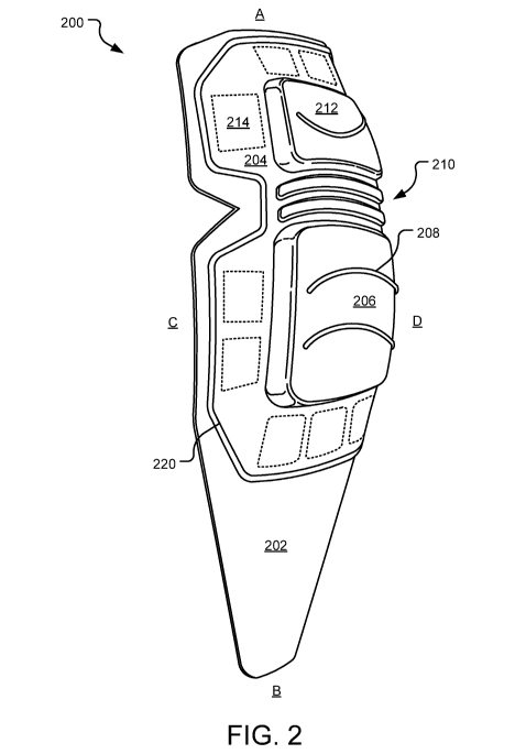
FIG. 2 is a perspective view of an example removable body pad 200. While the
depicted body pad 200 is a kneepad, in other implementations, one or more of a
user's shins,
thighs, groin, buttocks, waist, chest, shoulders, neck, elbows, and forearms
may benefit from
a similar form of body padding as that disclosed with respect to the user's
knees. When used,
the body pad 200 is oriented on a user's knee with Side A oriented upward
toward the user's
upper leg and side B downward toward the user's lower leg. Further, side C is
oriented
rearwardly and toward the user's knee and side D is oriented frontwardly and
away from the
user's knee.
The body pad 200 includes a padded insert 202, an optional cushioning layer
(not
shown), and a protective cap 204. The optional cushioning layer fills a void
between the
padded insert 202 and the protective cap 204 (see e.g., FIG. 3). In one
implementation, the
cushioning layer includes a matrix of resiliently compressible void cells. In
another
implementation, the cushioning layer is integrated with the padded insert 202
or the
protective cap 204 as a unified layer. In an example implementation, the
cushioning layer
has a thickness of 0.02" - 0.5". In other implementations, there is no void
between the
padded insert 202 and the protective cap 204 and thus no cushioning layer.
The padded insert 202 underlies the protective cap 204 and is located at a
rear of the
body pad 200. The padded insert 202 is made of a padded or cushioning material
(e.g., a
open cell or closed cell foam or matrix of resiliently compressible void
cells) or is filled with
a cushioning material (e.g., felt, down, feathers, or other resiliently
compressible materials).
The padded insert 202 may substantially or entirely cover a protected area of
a user's body
(e.g., the knee or elbow region of the user's body). Further, the padded
insert 202 may be
contoured to follow corresponding contours in the protected area of the user's
body (e.g.,
concave to fit a user's knee joint) and/or flexible to conform to movements of
the protected
area of the user's body (e.g., flexing of the user's knee joint). In an
example implementation,
the padded insert 202 has a thickness of 0.05"- 1".
The protective cap 204 overlies the padded insert 202 and is located at a
front of the
body pad 200. The protective cap 204 is harder than the padded insert 202 and
may be made
of an impact or abrasion resistant material (e.g., a solid plastic or rubber).
In an example
implementation, the protective cap 204 has a thickness of 0.02" - 0.2". The
protective
cap 204 may also substantially or entirely cover the protected area of the
user's body (e.g.,
the knee or elbow region of the user's body). In the depicted implementation,
the protective
cap 204 covers less area than the padded insert 202. In other implementations,
the protective
cap 204 covers an equal or greater area than the padded insert 202.
4
CA 02904117 2015-09-03
WO 2014/169147 PCT/US2014/033692
The inside surface of the protective cap 204 may also be contoured to follow
corresponding contours in the protected area of the user's body and/or
flexible to conform to
movements of the protected area of the user's body. Further, the outside
surface of the
protective cap 204 may be similarly contoured and/or flexible. In other
implementations, the
outside surface of the protective cap 204 may have one or more facets molded
thereon to
achieve a desired level of stability (e.g., provide a stable platform for
resting the user's elbow
in a elbow pad implementation). The protective cap 204 is stitched along a
periphery of the
protective cap 204 to the padded insert 202 (see e.g., stitching 220). In
other
implementations, the protective cap 204 is glued, welded, mechanically
attached (e.g., via a
grommet or rivet), or selectively removably attached (e.g., via hook-and-loop
tape) to the
padded insert 202.
The protective cap 204 includes protruding portions 206, 212 that
substantially
protrude frontwardly from the remaining potion of the protective cap 204
(i.e., protruding
greater than a thickness of a corresponding garment or greater than 0.1 in).
The protruding
portions 206, 212 may offer increased impact absorption by resiliently
deflecting rearwardly
upon impact. In some implementations, a resilient deflection of the protective
cap 204
engages the cushioning layer to absorb energy from the impact. In some
implementations,
the protruding portions 206, 212 are referred to as discrete sections of a
singular protruding
portion. Further, the protruding portions 206, 212 may be thicker than other
areas of the
protective cap 204 in order to maximize performance of the protective cap 204
while
minimizing weight and the cost of manufacturing the body pad 200. In
other
implementations, the protective cap 204 may include a number of removable
layers that are
selectively removed as the protective cap 204 is damaged or worn out to
provide a fresh
protective cap 204 outer surface. In still other implementations, the
protective cap 204 has no
protruding portions 206, 212 and its entirety lies in substantially the same
plane or within the
same simple curved plane.
The protective cap 204 includes gripping ridges (e.g., ridge 208) that offer
the user
increased traction when engaging a surface using the body pad 200. For
example, the
gripping ridges may offer the user increased traction at the user's knees when
the user is
crawling on the ground. Some of the gripping ridges arc concave in a downward
direction in
order to maximize traction of the body pad 200 in the downward direction.
Other gripping
ridges may be concave in an upward direction in order to maximize traction of
the body
pad 200 in the upward direction. In other implementations, the gripping ridges
may have
5
CA 02904117 2015-09-03
WO 2014/169147 PCT/US2014/033692
other shapes and orientations on the protective cap 204. In still other
implementations, no
gripping ridges are included on the protective cap 204.
The protective cap 204 also includes a flexing region 210 that separates the
lower
protruding portion 206 from the upper protruding portion 212. The flexing
region 210 aids
flexing of the protective cap 204 in a desired area. For example, the flexing
region 210 is
located at or near a point where the body pad 200 is seated on the user's
knee. As the knee is
flexed, the protective cap 204 preferentially flexes about the flexing region
210 to conform
closely with the user's knee in a variety of orientations of the knee joint.
In other
implementations, the flexing region is oriented and/or located differently
than that depicted in
FIG. 2 depending on where and how the body pad 200 is intended to be flexed.
Further,
some body pads may incorporate multiple flexing regions or the entire surface
of the body
pad may be flexible.
A window in a corresponding garment (not shown, see e.g., window 632 of
garment 624 of FIG. 6) provides a potential source of contaminants (e.g.,
solids, liquids,
and/or gases) entering the garment and coming in contact with the user or
becoming lodged
between the user and the body pad 200, causing discomfort or injury. In order
to keep the
contaminants out, the body pad 200 also includes fastening pads (e.g., pad
214) arranged
around the periphery of the protective cap 204. The fastening pads may include
hook-and-
loop material, snaps, buttons, clasps, or any other attaching device that
selectively attaches
and detaches the body pad 200 to a corresponding garment. The fastening pads
may
surround or substantially surround the protective cap 204 in order to provide
a partial, near-
complete, or complete seal against external contaminants from entering the
garment. The
seal may be adapted to prevent substantial solid, liquid, and/or gaseous
contaminants from
entering the garment. In one implementation, a region of the periphery of the
protective
cap 204 is devoid of the fastening pads or order to allow the user to more
easily pry the body
pad 200 from the garment using the user's fingers. This region may also allow
the body
pad 200 to more readily bend without the fastening pads restraining the
deflection of the body
pad 200.
Other implementations do not include the fastening pads. For example, one or
more
zippers or zipper seals may extend around the periphery of the protective cap
204 in order to
selectively attach and detach the body pad 200 to the garment. For further
details regarding
the attachment / detachment of the body pad 200 to / from the garment, see
FIGs. 7-9 and
detailed descriptions thereof.
6
CA 02904117 2015-09-03
WO 2014/169147 PCT/US2014/033692
Each of the components of the body pad 200 may be thermo-formed or injection
molded, for example. Further, each of the components of the body pad 200 may
be selected
from a group of fire-retardant materials or "no-melt, no-drip" materials to
improve the user's
safety.
FIG. 3 is a cross-sectional view of an example removable body pad 300. While
the
depicted body pad 300 is a kneepad, other implementations of the disclosed
body padding
may protect other areas of a user's body. When used, the body pad 300 is
oriented on the
user's knee with side A oriented upward toward the user's upper leg and side B
downward
toward the user's lower leg. Further, side C is oriented rearwardly and toward
the user's
knee and side D is oriented frontwardly and away from the user's knee.
The body pad 300 includes a padded insert 302, a cushioning layer 338, and a
protective cap 304. The padded insert 302 underlies the protective cap 304 and
is located at a
rear of the body pad 300. The padded insert 302 may substantially or entirely
cover a
protected area of the user's body, may be contoured to follow corresponding
contours in the
protected area of the user's body, and/or may be flexible to conform to
movements of the
protected area of the user's body.
The cushioning layer 338 fills a void between the padded insert 302 and the
protective
cap 304 and provides additional cushioning and/or impact protection to the
user. In one
implementation, the cushioning layer 338 includes the matrix of resiliently
compressible void
cells shown in FIG. 3, although other cushioning layer 338 arrangements are
contemplated
herein. For example, the cushioning layer 338 may have a different arrangement
of void cells
(e.g., one or more matrices of void cells stacked over one another and
optionally attached
together). In other implementations, there is no void between the padded
insert 302 and the
protective cap 304 and thus no cushioning layer 338.
The protective cap 304 overlies the cushioning layer 338 and is stitched along
a
periphery of the protective cap 304 or other otherwise attached to the padded
insert 302. In
another implementation, the protective cap 304 is selectively removably
attached to the
padded insert 302 via a snap fit connection. Further, the protective cap 304
may include two
pieces that snap together with the padded insert 302 compressed there between.
The
protective cap 304 may also substantially or entirely cover the protected area
of the user's
body, may also be contoured to follow corresponding contours in the protected
area of the
user's body and/or may also be flexible to conform to movements of the
protected area of the
user's body.
7
CA 02904117 2015-09-03
WO 2014/169147 PCT/1JS2014/033692
The protective cap 304 includes protruding portions 306, 312 that
substantially
protrude frontwardly from the remaining potion of the protective cap 304 that
offer increased
impact absorption by resiliently deflecting rearwardly upon impact. The
protective cap 304
may also include gripping ridges (e.g., ridge 308) that offer the user
increased traction when
engaging a surface using the body pad 300. The protective cap 304 may also
include a
flexing region 310 that separates the lower protruding portion 306 from the
upper protruding
portion 312 and aids flexing of the protective cap 304 in a desired area.
The body pad 300 also includes fastening pads (not shown) or other sealing
arrangements oriented around the periphery of the protective cap 304 that
selectively attach
and detach the body pad 300 to a corresponding piece of clothing (not shown,
see e.g.,
garment 624 of FIG. 6). The fastening pads may surround or substantially
surround the
protective cap 304 in order to provide a partial, near-complete, or complete
seal against
external contaminants from entering the user's clothing.
FIG. 4 is a front view of an example removable body pad 400. While the
depicted
body pad 400 is a kneepad, other implementations of the disclosed body padding
may protect
other areas of a user's body. When used, the body pad 400 is oriented on the
user's knee
with side A oriented upward toward the user's upper leg and side B downward
toward the
user's lower leg. Further, the depicted side of the body pad 400 is oriented
frontwardly and
away from the user's knee.
The body pad 400 includes a padded insert 402, an optional cushioning layer
(not
shown), and a protective cap 404. The padded insert 402 underlies the
protective cap 404
and is located at a rear of the body pad 400. The padded insert 402 may
substantially or
entirely cover a protected area of the user's body, may be contoured to follow
corresponding
contours in the protected area of the user's body, and/or may be flexible to
conform to
movements of the protected area of the user's body.
The protective cap 404 overlies the padded insert 402 and is stitched along a
periphery
of the protective cap 404 (see e.g., stitching 420) or otherwise attached to
the padded
insert 402. In another implementation, the protective cap 404 is selectively
removably
attached to the padded insert 402 via a snap fit connection. Further, the
protective cap 404
may include two pieces that snap together with the padded insert 402
compressed there
between. The protective cap 404 may also substantially or entirely cover the
protected area
of the user's body, may also be contoured to follow corresponding contours in
the protected
area of the user's body and/or may also be flexible to conform to movements of
the protected
area of the user's body.
8
CA 02904117 2015-09-03
WO 2014/169147 PCT/US2014/033692
The protective cap 404 includes protruding portions 406, 412 that
substantially
protrude frontwardly from the remaining potion of the protective cap 404 that
offer increased
impact absorption by resiliently deflecting rearwardly upon impact. The
protective cap 404
may also include gripping ridges (e.g., ridge 408) that offer the user
increased traction when
engaging a surface using the body pad 400. The protective cap 404 may also
include a
flexing region 410 that separates the lower protruding portion 406 from the
upper protruding
portion 412 and aids flexing of the protective cap 404 in a desired area.
The body pad 400 also includes fastening pads (e.g., pad 414) or other sealing
arrangements oriented around the periphery of the protective cap 404 that
selectively attach
and detach the body pad 400 to a corresponding piece of clothing (not shown,
see e.g.,
garment 624 of FIG. 6). The fastening pads may surround or substantially
surround the
protective cap 404 in order to provide a partial, near-complete, or complete
seal against
external contaminants from entering the user's clothing.
FIG. 5 is a rear view of an example removable body pad 500. While the depicted
body
pad 500 is a kneepad, other implementations of the disclosed body padding may
protect other
areas of a user's body. When used, the body pad 500 is oriented on the user's
knee with side
A oriented upward toward the user's upper leg and side B downward toward the
user's lower
leg. Further, the depicted side of the body pad 500 is oriented rearwardly and
toward the
user's knee.
The body pad 500 includes a padded insert 502, an optional cushioning layer
(not
shown), and a protective cap (not shown). The padded insert 502 underlies the
protective
cap, which is stitched to the padded insert 502 along a periphery of the
protective cap (see
e.g., stitching 520). The padded insert 502 may substantially or entirely
cover a protected
area of the user's body, may be contoured to follow corresponding contours in
the protected
area of a user's body, and/or may be flexible to conform to movements of the
protected area
of the user's body.
In other implementations, the padded insert 502 includes a fastening strips or
pads (not
shown) at the rear of the padded insert 502. The fastening strips or pads may
include hook-
and-loop tape, snaps, buttons, clasps, zipper seals, or any other attaching
device that
selectively attaches and detaches the body pad 500 to an interior panel of the
user's clothing
(not shown, see e.g., inner layer 630 of FIG. 6). For further details
regarding the attachment /
detachment of the body pad 500 to / from the clothing, see FIGs. 7-9 and
detailed
descriptions thereof.
9
CA 02904117 2015-09-03
WO 2014/169147 PCT/US2014/033692
FIG. 6 is a front view of an example garment 624 with a body pad pocket 626
and
corresponding window 632. The depicted garment 624 is a pants leg, although,
other areas of
a user's clothing may incorporate similar features as those disclosed with
specific reference
to the pants leg of FIG. 6. Further, the garment 624 is often a fabric
material, but may be
made of other materials suitable for the user's clothing (e.g., rubber for
waders). In some
implementations, the pants leg (with corresponding body pad (not shown)) is
selectively
removable (e.g., via a zipper) from a corresponding pair of pants. Modular
options for the
pants leg may be available with different characteristics (e.g., with pads,
without pads, etc.).
The garment 624 includes the pocket 626 in the knee area of the garment 624.
The
pocket 626 is made up of an outer layer 628 and an inner layer 630. The outer
layer 628 is
stitched to the inner layer 630 about a periphery of the pocket 626 (see
stitching 634). In
other implementations, the outer layer 628 is stitched to the outside of the
garment 624,
where the garment 624 forms the inner layer 630. In still other
implementations, the inner
layer 630 is stitched to the inside of the garment 624, wherein the garment
624 forms the
outer layer 628.
A gap (not shown) may be left in the stitching 634 to allow a corresponding
body pad
(not shown, see e.g., body pad 200 of FIG. 2) to be selectively inserted into
the pocket 626
through the gap. In some implementations, the gap is selectively closed via
fastener (e.g.,
hook-and-loop tape). The body pad is at least visible, and may also protrude
through the
window 632. Further, the body pad is inserted into and removed from the pocket
626 via the
window 632. The window 632 is sized and placed such that a protective cap
portion (not
shown) of the body pad occupies the entire window 632. In some
implementations, the
protective cap portion protrudes out of the window 632.
The garment 624 further includes a fastening strip 640 stitched to the inner
layer 630.
The fastening strip 640 corresponds to a matching fastening strip on an inside
surface of a
corresponding body pad. In other implementations, the fastening strip 640 is
not included or
is placed in a different location. The fastening strip 640 may include hook-
and-loop tape,
snaps, buttons, clasps, zipper seals, or any other attaching device that
selectively attaches and
detaches the body pad to the garment 624.
FIG. 7 is a perspective view of an example body pad pocket 726 with a
removable
body pad 700 incorporated therein. The pocket 726 is made up of an outer layer
728 and an
inner layer (not shown) attached to a corresponding garment 724. The outer
layer 728 is
stitched to the inner layer about a periphery of the pocket 726 (see stitching
734). In some
CA 02904117 2015-09-03
WO 2014/169147 PCT/US2014/033692
implementations, a gap (not shown) is left in the stitching 734 to allow the
body pad 700 to
be selectively inserted into the pocket 726.
The pocket 726 further includes a window 732 through which the body pad 700 is
at
least visible, and through which a portion of the body pad 700 may protrude
(see e.g.,
protruding portions 206, 212 of the protective cap 204 of FIG. 2). In some
implementations,
the body pad 700 is inserted into the pocket 726 via the window 732. Further,
the
window 732 is sized and placed such that a protective cap portion 704 of the
body pad 700
occupies the substantially the entire window 732 (e.g., over 95% of the window
732) or a
majority of the window 732. In some implementations, the protective cap
portion protrudes
out of the window 732.
The pocket 726 may include fastening pads (not shown) attached to the inside
of the
outer layer 728. The fastening pads correspond to matching fastening pads on
an outside
surface of the body pad 700 (see e.g., fastening pad 214 of FIG. 2). The
fastening pads may
include hook-and-loop tape, snaps, buttons, clasps, zipper seals, or any other
attaching device
that selectively attaches and detaches the body pad 700 to the pocket 726. The
fastening pads
may surround or substantially surround the window 732 in order to provide a
partial, near-
complete, or complete seal against external contaminants from entering the
pocket 726. In
one implementation, a region of the periphery of the window 732 is devoid of
the fastening
pads. This region allows the user to more easily pry the body pad 700 from the
garment 724
using the user's fingers and hands.
In other implementations, the pocket 726 and the body pad 700 do not include
fastening pads. The pocket 726 may be tight enough and/or stretchable enough
to hold the
body pad 700 in place with respect to the window 732 without fastening pads.
In one
implementation, the pocket 726 includes elastane or other resiliently
stretchable fabric
materials. In another implementation, the body pad 700 includes a channel that
receives the
pocket 726 around the window 732 to provide a more secure fit to the window
732. In still
another implementation, the pocket 726 includes an elastic or otherwise
adjustable-length
drawstring to tighten the pocket 726 around the protective cap portion of the
body pad 700
and provide a better seal between the window 732 and the body pad 700.
FIG. 8 is a front view of an example garment 824 with a removable body pad 800
incorporated within the garment 824. The depicted garment 824 is a pants leg,
although,
other areas of a user's clothing may incorporate similar features as those
disclosed with
specific reference to the pants leg of FIG. 8.
11
CA 02904117 2015-09-03
WO 2014/169147 PCT/US2014/033692
The garment 824 includes a pocket 826 in the knee area of the garment 824. The
pocket 826 is made up of an outer layer 828 and an inner layer (not shown).
The outer
layer 828 is stitched to the inner layer about a periphery of the pocket 826
(see stitching 834).
In some implementations, a gap (not shown) is left in the stitching 834 to
allow the body
pad 800 to be selectively inserted into the pocket 826 through the gap. The
pocket 826
further includes a window 832 through which the body pad 800 is at least
visible, and
through which a portion of the body pad 800 may protrude (e.g., protruding
portions 206, 212
of the protective cap 204 of FIG. 2). In some implementations, the body pad
800 is inserted
into the pocket 826 via the window 832. Further, the window 832 is sized and
placed such
that a protective cap portion of the body pad 800 occupies the entire window
832. In some
implementations, the protective cap portion protrudes out of the window 832.
The garment 824 further includes fastening pads (not shown) stitched to the
inside of
the outer layer 828. The fastening pads correspond to matching fastening pads
on the outside
surface of the body pad 800 (see e.g., fastening pad 214 of FIG. 2). The
fastening pads may
include hook-and-loop tape, snaps, buttons, clasps, zipper seals, or any other
attaching device
that selectively attaches and detaches the body pad 800 to the garment 824.
The fastening
pads may surround or substantially surround the window 832 in order to provide
a partial,
near-complete, or complete or seal against external contaminants from entering
the
garment 824. In one implementation, a region of the periphery of the window
832 is devoid
of the fastening pads. This region allows the user to more easily pry the body
pad 800 from
the garment 824 using the user's fingers and hands.
In yet other implementations, the pocket 826 is selectively removable from the
garment 824, while the body pad 800 remains fixedly attached to the pocket
826. In still
another implementation, there is no pocket 826. Instead, a padded insert
(e.g., padded
insert 202 of FIG. 2) is attached to the inside of the garment 824 and the
protective cap (e.g.,
protective cap 204 of FIG. 2) is selectively removably attached to the outside
of the
garment 824. In still another implementation, the body pad 800 is directly
attached to the
user's skin (e.g., via a viscoelastic pressure adhesive) rather than (or in
addition) to the
pocket 826.
In another implementation, the first interior portion of the body pad 800 is
permanently attached to the garment 824. A second exterior portion of the body
pad 800
snaps or otherwise selectively removably attaches to the first interior
portion of the body
pad 800. Further, the second exterior portion of the body pad 800 may slide
along one or
more rails (not shown) that arc included in the first interior portion and
snap into place on the
12
CA 02904117 2015-09-03
WO 2014/169147 PCT/US2014/033692
rails. Further, if the rails are oriented vertically, the second exterior
portion of the body
pad 800 may be vertically adjustable to accommodate variations in body shape
and size that
affect the desired body pad location.
In still another implementation, the body pad 800 includes straps that wrap
around the
user's body, extending through channels in the garment 824 and tighten around
the user's
body to hold the body pad 800 in place. The body pad 800 may utilize one or
more of the
disclosed systems and methods for attachment to the garment 824 and/or the
user.
FIG. 9 is a detail perspective view of an example removable body pad 900
incorporated within a garment window 932 of a garment 924. The depicted
garment 924 is a
pants leg, although, other areas of a user's clothing may incorporate similar
features as those
disclosed with specific reference to the pants leg of FIG. 9.
The garment 924 includes a pocket 926 in the knee area of the garment 924. The
pocket 926 is made up of an outer layer 928 and an inner layer (not shown).
The outer
layer 928 is stitched to the inner layer about a periphery of the pocket 926.
The body pad 900
is at least visible, and may also protrude (see e.g., protruding portions 206,
212 of the
protective cap 204 of FIG. 2) through the window 932 of the pocket 926. In
some
implementations, the body pad 900 is inserted into the pocket 926 via the
window 932.
Further, the window 932 is sized and placed such that a protective cap portion
of the body
pad 900 occupies substantially the entire window 932, or at least a majority
of the window.
In some implementations, the protective cap portion protrudes out of the
window 932.
FIG. 10 illustrates example operations 1000 for installing and uninstalling a
removable
body pad from an associated garment. In an inserting operation 1010, a body
pad is inserted
into a garment pocket. The garment pocket is a pocket within a garment that is
intended to
removeably receive the body pad. The body pad is either inserted into the
pocket through an
aperture in the pocket within the garment or through a window in the pocket to
the outside of
the garment. In some implementations, the window or aperture is smaller than
the outside
dimensions of the body pad. However, the body pad may be bent or otherwise
compressed to
fit through the window or aperture into the pocket.
In a positioning operation 1020, the body pad is positioned within the pocket
such that
a protective cap portion of the body pad occupies the area of the window such
that only the
protective cap portion is visible. In other implementations, an area of the
body pad
surrounding the protective cap is visible through the window as well. In some
implementations, the protective cap portion includes a shoulder that matches
the shape and
size of the window to help align and position the body pad in the window. In
other
13
CA 02904117 2015-09-03
WO 2014/169147 PCT/US2014/033692
implementations, the protective cap portion is merely centered within the
window or
alignment marks are included on the protective cap portion to aid user
alignment of the
protective cap portion in the window.
In a securing operation 1030, the body pad is secured to the garment pocket.
The body
pad includes selective attachments (e.g., hook-and-loop tape) on an outside
facing surface of
the body pad in an orientation that surrounds the window when the body pad is
correctly
positioned within the pocket. Further, the garment pocket includes
corresponding selective
attachments on an inside facing surface of the garment pocket around the
window.
Additional selective attachments maybe included on the inside facing surface
of the body pad
and the inside surface of an inner layer of the gaiment pocket. The selective
attachments of
the body pad and the garment pocket are aligned and secured together (e.g., by
applying
compressive force). The garment with body pad is then ready for use.
When the user desires to remove and/or replace the body pad, in a releasing
operation 1040, the body pad is released from the garment pocket. The user may
apply a
tensile or shearing force to the garment pocket and the body pad to release
the selective
attachments securing the body pad to the garment pocket.
In a removing operation 1050, the body pad is removed from the garment pocket
in a
similar manner as the body pad was inserted into the garment pocket in
operation 1010, but in
reverse order. The body pad may then be stored for later use, washed, or
discarded in favor
of a new body pad.
The logical operations making up the embodiments of the invention described
herein
are referred to variously as operations, steps, objects, or modules.
Furthermore, it should be
understood that logical operations may be performed in any order, adding or
omitting
operations as desired, unless explicitly claimed otherwise or a specific order
is inherently
necessitated by the claim language.
The above specification, examples, and data provide a complete description of
the
structure and use of exemplary embodiments of the invention. Since many
embodiments of
the invention can be made without departing from the spirit and scope of the
invention, the
invention resides in the claims hereinafter appended. Furthermore, structural
features of the
different embodiments may be combined in yet another embodiment without
departing from
the recited claims.
14