Note: Descriptions are shown in the official language in which they were submitted.
CA 02904147 2015-09-04
- 1 -
Bucket wheel for removing materials from a material composite,
particularly of high hardness
Description
The present invention relates to a bucket wheel for removing
materials from a material composite, particularly of high
hardness, having a base body which extends about a bucket wheel
rotational axis and on which, distributed about the
circumference a plurality of buckets with bucket cutters are
accommodated, and wherein a plurality of cutting teeth, which
can be moved on respective orbits about the bucket wheel
rotational axis by rotation of the base body, are arranged on
each bucket cutter. The invention is also directed at a bucket
for a bucket wheel and at a method for removing materials with
such a bucket wheel.
PRIOR ART
Bucket wheels are used, in particular, for bucket wheel
excavators, and bucket wheel excavators are generally used in
surface mining for removing and transporting away large
quantities of materials. In this context, the material is
released from a material composite, and the material composite
can be, for example, a strata formation or else an artificially
produced heap. Hard materials have compressive strengths of
more than 5.0 MPa here, with the result that bucket wheels have
to be embodied in a particular way in order to be compatible
with the relatively high hardness of the material composite.
The bucket wheel is made to rotate about its bucket wheel
rotational axis by a drive of the bucket wheel excavator, and
the material which is to be removed, such as brown coal, chalk,
limestone and the like, is released from the material composite
CA 02904147 2015-09-04
- 2 -
by the rotating bucket wheel and lifted vertically in buckets,
in order to subsequently pass onto a transportation belt for
onward transportation. Hard materials for removal are, for
example, hard brown coal, hard coal, marl or the like. The
bucket wheel has, as a load-bearing base structure, a base body
which rotates about the bucket wheel rotational axis, which
runs approximately horizontally with respect to the overburden
slope of the strata formation, and the bucket wheel is pivoted
laterally by the bucket wheel excavator in order to generate
advancing approximately in the direction of the bucket wheel
rotational axis. For this purpose, the bucket wheel excavator
has a superstructure, and the pivoting can be carried out by
rotating on a caterpillar track unit, but there is also the
possibility of the bucket wheel being moved relative to the
strata formation by moving the bucket wheel excavator by means
of the caterpillar track unit.
A plurality of buckets which have bucket cutters with a
plurality of cutting teeth are arranged on the approximately
cylindrical base body. In this context, each bucket is
frequently assigned a main bucket cutter and one or more so-
called pre-cutters, and the material released from the material
composite by the cutting teeth passes into the bucket and
subsequently onto the transportation belt of the bucket wheel
excavator.
For example, DE 10 2004 033 934 Al presents a bucket wheel for
removing materials from a material composite, and the bucket
wheel is operated with a bucket wheel excavator for cutting
below grade underneath its supporting surface. A plurality of
buckets are arranged on the base body of the bucket wheel, and
the buckets have approximately triangular or trapezoidal bucket
cutters on which a plurality of cutting teeth are arranged. As
a result of the lateral pivoting of the jib of the bucket wheel
excavator, a side section of the bucket cutter always enters
CA 02904147 2015-09-04
- 3 -
into engagement with the material composite, with the result
that either a left-hand or right-hand side section, which is
referred to as a segment enters into engagement with the
material composite depending on the pivoting direction of the
jib of the bucket wheel excavator.
Either radially extending cells or annular spaces are provided
in the base body of the bucket wheel corresponding to the
number of buckets attached to the bucket wheel, the excavated
mass of material being able to escape into said cells or
annular spaces when the bucket is lifted, in order to avoid
impeding the digging process. In order to avoid putting the
emptying of the cells or annular spaces at risk, in particular
in the case of sticky materials, an excessively high number of
cells or annular spaces on the base body is not desired. In the
case of small bucket wheels in the range between 4 m and 5 m
diameter, the number of annular spaces can be limited to
approximately 10 to 15, and in the case of large bucket wheels
with 15 m to 20 m diameter, this number can be limited to
approximately 20 to 25.
In addition to the triangular or trapezoidal bucket cutters
which are shown, buckets are known with a U-shaped bucket frame
which is attached to the base body to the left and right of the
cell spaces or annular spaces using bolts and wedges on the
base body, wherein each bucket has at least one bucket back for
holding material and a bucket cutter on which the cutting teeth
are generally attached.
The side sections of the bucket cutters have a steep attitude
angle with respect to the bucket wheel rotational axis. This
attitude angle relates to the lower part of the side sections,
which are just still actively involved in the digging process.
In the known designs of bucket wheels, this angle is typically
above 602. As a result, a relatively steep angle can be
CA 02904147 2015-09-04
- 4 -
implemented between the side slope and the front cut slope of
the bucket.
During the excavation of relatively hard materials with
compressive strengths of more than 5 MPa, it is frequently the
case that the number of bucket cutters has to be higher than
the number of buckets or of the cell spaces or annular spaces
on the bucket wheel. In this case, the attachment of one or
more additional bucket cutters without bucket backs, also
referred to as pre-cutters, to an annular carrier of the base
body of the bucket wheel is known. The equipping with teeth,
that is to say the arrangement and the positioning of the
cutting teeth is the same for all the bucket cutters including
the so-called pre-cutter, in order to ensure an equal digging
cross section.
During the cutting of relatively hard materials with a
compressive strength of over 5.0 MPa it has, however, been
found that the digging force load on a cutting tooth can be
very high, with the result that the number of cutting teeth on
a bucket cutter has to be increased significantly in order to
reduce the digging cross sections for each individual cutting
tooth. However, an excessively high number of teeth on a bucket
cutter is limited owing to the available space for the
arrangement of the cutting teeth on the bucket cutter, and at
the same time impedes the flow of released chunks of material
from the material composite. In addition, the objective is to
introduce fewer individual strong digging force impulses into
the entire system of the bucket wheel excavator but instead to
introduce a plurality of attenuated digging force impulses,
with the result that the digging forces which occur are
substantially homogenized.
Furthermore, it has become apparent that particularly when
excavating many useful minerals such as coal, chalk, limestone
CA 02904147 2015-09-04
- 5 -
and the like a relatively high degree of comminution with
limitation of the maximum sizes of the chunks is desired. A
defined digging cross section for each individual cutting tooth
requires a sufficiently large distance between two adjacent
cutting teeth on a bucket cutter. Also, a relatively large
distance between the adjacent cutting teeth on the
circumference of the bucket wheel is advantageous when breaking
through hard occlusions, for example layers of siderite, clay
ironstone or boulder flint and nodules of boulder flint.
However, the size of the bucket wheel must also remain limited,
and the bucket wheel also cannot be widened to any desired
extent in the direction of the bucket wheel rotational axis, so
as to ensure sufficient distances between the cutting teeth
when there is a large number of cutting teeth.
DISCLOSURE OF THE INVENTION
The object of the invention is to develop a bucket wheel for
removing relatively hard materials having an increased number
of cutting teeth, each of which can be assigned a defined
digging cross section. In particular, the size of the chunks of
removed material is to continue to be limited here.
This object is achieved on the basis of a bucket wheel for
removing materials from a material composite according to the
preamble of claim 1, on the basis of a bucket for such a bucket
wheel according to the preamble of claim 10 and on the basis of
a method according to claim 12 having the respectively
characterizing features. Advantageous developments of the
invention are specified in the dependent claims.
The invention includes the technical teaching that the cutting
teeth which are accommodated on bucket cutters which are
adjacent to one another are arranged at least partially offset
with respect to one another, with the result that said bucket
CA 02904147 2015-09-04
- 6 -
cutters can be moved on orbits which are offset in the
direction of the bucket wheel rotational axis.
As a result of the offset arrangement of the cutting teeth on
bucket cutters which are arranged adjacent to one another it is
ensured that the bucket cutters which follow one another in the
circumferential direction of the bucket wheel are equipped
differently with teeth, with the result that the number of
cutting teeth which are arranged on a bucket cutter can be
reduced, but the number of bucket cutters which can be arranged
overall on a bucket wheel can remain the same or even be
increased. The invention also comprises here the possibility of
accommodating two or more rows of cutting teeth on just one
bucket cutter if the geometry of the bucket cutter permits it,
15. for example through corresponding lengthening of the bucket
cutter in the rotational direction. As a result, cutting teeth
can also be accommodated on a bucket cutter in various rows of
teeth which follow one another in the rotational direction.
The offset between the cutting teeth can be embodied in such a
way that a cutting tooth on a subsequent bucket cutter fills a
tooth gap which is formed between two cutting teeth on a
preceding bucket cutter. As a result of the offset between the
cutting teeth, orbits of the cutting teeth are produced which
are offset in the direction of the bucket wheel rotational
axis, wherein two cutting teeth which can be moved on a common
orbit are not arranged on bucket cutters which follow one
another in the circumferential direction of the bucket wheel.
The cutting teeth which can be moved on common orbits are
accommodated here on bucket cutters, between which at least one
further bucket cutter with different equipment with teeth is
present.
At least 2, 3, 4 or more bucket cutters with cutting teeth
which are arranged offset with respect to one another can
CA 02904147 2015-09-04
- 7 -
particularly advantageously be accommodated distributed in a
periodic sequence in the circumferential direction of the base
body, with the result that each cutting tooth on adjaceht
bucket cutters is assigned a separate digging cross section.
The number of cutting teeth per bucket which are accommodated
on a bucket cutter can be divided here by the number of bucket
cutters with different equipment with teeth. If, for example,
two bucket cutters are provided which each have cutting teeth
in a first arrangement and in a second arrangement in a
periodic sequence in the circumferential direction of the base
body, said bucket cutters permit the necessary number of
cutting teeth on each of the bucket cutters to be halved. If
three bucket cutters with cutting teeth which are respectively
arranged offset in a periodic sequence in the circumferential
direction of the base body are provided, the necessary number
of cutting teeth per bucket cutter can be limited to a third.
In this context, each cutting tooth can be assigned the same
digging cross section. The tooth arrangement of each bucket
cutter and the sequence of bucket cutters with different
arrangements in the period is appropriately determined here in
such a way that each cutting tooth has to cut a separate
digging cross section and the digging cross sections of the
cutting teeth which are installed on a bucket cutter should not
overlap here.
According to one advantageous development of the bucket wheel
according to the invention, the bucket cutters are embodied in
an arcuate shape and have a bucket cutter width which runs in
the direction of the bucket wheel rotational axis and a bucket
cutter depth which runs in the radial direction, wherein the
ratio of the bucket cutter depth with respect to the bucket
cutter width has a value of 0.1 to 0.7, preferably from 0.15 to
0.5 and particularly preferably from 0.2 to 0.4. Simply due to
the relatively flat design of the bucket cutters with a large
width and a large digging depth, a relatively flat design of
CA 02904147 2015-09-04
- 8 -
the buckets is produced, with the result that appropriate
separation of the cross-sectional profiles of the adjacent
cutting teeth is achieved. The specified ratio between the
bucket cutter depth and the bucket cutter width forms here a
characteristic number for the flat design of the bucket,
wherein the bucket cutter depth is understood to refer to the
maximum bucket digging depth, with a maximum radial distance
between all the cutting teeth installed on the bucket wheel or
on all the bucket cutters being understood. The bucket width is
understood to refer to the maximum distance between the outer
cuttinq teeth in the direction of the bucket wheel rotational
axis.
The bucket cutters have side sections which run to a point
towards the bucket center, and the inventive design of the
bucket is reflected in the attitude angle between the direction
of extent of the side sections and the bucket wheel rotational
axis. For example, the direction of extent of the side sections
can enclose an attitude angle of less than 60 , preferably of
less than 55 and particularly preferably of less than 50 with
the bucket wheel rotational axis. If the bucket cutters are
embodied in an arcuate shape, the direction of extent of the
side sections can be formed by a tangent or a secant which is
guided by the cutting teeth arranged on the side sections of
the bucket cutters.
Furthermore, the inventive design of the blades is also
reflected in the ratio between a cutting circle diameter of the
bucket wheel and the bucket cutter width. The ratio of the
cutting circle diameter with respect to the bucket width can
have a value of less than 4, preferably of less than 3.5 and
particularly preferably of less than 3 in the case of bucket
wheels with a cutting circle diameter of less than 7 m, a value
of less than 5, preferably of less than 4.5 and particularly
preferably of less than 4 in the case of bucket wheels with a
CA 02904147 2015-09-04
- 9 -
cutting circle diameter of 7 m to 13 m, a value of less than 6,
preferably of less than 5.5 and particularly preferably of less
than 5 in the case of bucket wheels with a cutting circle
diameter of 13 m to 18 m, and a value of less than 7,
preferably of less than 6.5 and particularly preferably of less
than 6 in the case of bucket wheels with a cutting circle
diameter of more than 18 m. As a result of the very wide
embodiment of the bucket wheel compared to the cutting circle
diameter, a milling bucket wheel is produced, which permits a
flat cutting angle relative to the slope edge. The maximum
dimensions of the cross-sectional profiles for the cutting
teeth determine essentially the distribution of the particle
sizes of the released material here and can be used, in
combination with the fissuring characteristic numbers of the
removed material for the evaluation of the frequency of
oversize material and flowing capability of the removed
material.
The proportion of oversize material in the conveyed material
can be additionally reduced by expedient configuration of a
uniform gap between the individual bucket cutters arranged on
the circumference of the bucket wheel. A particularly
advantageous refinement can be obtained by the bucket cutters
being able to be at a distance from one another in the
rotational direction which corresponds approximately to twice
the main dimensions of the digging cross sections. This
generates a screening function which means that the maximum
particle size of the removed material which passes into the
bucket shells is limited and the frequency of oversize material
can be limited.
According to one advantageous embodiment of the bucket wheel
according to the invention, the buckets have bucket frames on
which the bucket cutters and, in particular, bucket shells are
accommodated, and wherein the buckets are detachably arranged
CA 02904147 2015-09-04
- 10 -
on the base body. In order to be able to quickly change the
large number of bucket cutters when performing maintenance of
the bucket wheel, it is appropriate to arrange the buckets
detachably on the base body.
It is also advantageous that the bucket frame of the buckets
can have a H-shaped structure with two longitudinal beams
running approximately parallel and a transverse beam running
between the longitudinal beams, the bucket cutters are
accommodated on the longitudinal beams and extend between them
in an approximately arcuate shape. The base body of the bucket
wheel can have two annular carriers which extend as rotational
bodies about the bucket wheel rotational axis, wherein
transverse struts run at periodical intervals with respect to
one another between the annular carriers. In this context the
annular spaces into which the excavated material mass can
escape during the lifting of the buckets come about between the
annular carriers and the transverse struts. The transverse beam
advantageously corresponds here in its position to the
transverse strut, in order to avoid unnecessarily reducing the
annular space under the bucket cutters. The bucket cutters are
accommodated here on the longitudinal beams and run in an
approximately arcuate shape between the two longitudinal beams.
The bucket frame can be detachably arranged on the base body
here, with the result that minimum expenditure in terms of
assembly and disassembly is produced if a bucket is to be
removed from the bucket wheel.
A bucket can have at least two, preferably three and
particularly preferably four or more bucket cutters, wherein
one of the bucket cutters forms a main bucket cutter on which a
bucket shell is arranged. The other bucket cutters form here
the so-called pre-cutters, wherein the first bucket cutter on
each bucket does not necessarily have to be the main bucket
cutter, and pre-cutters can precede a main bucket cutter which
CA 02904147 2015-09-04
- 11 -
is arranged further forward in the rotational direction of the
bucket wheel, on a second bucket, which pre-cutters are
arranged on a first bucket which precedes in the rotational
direction. The arrangement of the bucket shell can be provided
adjacent to the main bucket cutter, without a retaining
connection being present between the bucket shell and the main
bucket cutter. In particular, the bucket shells can be
preferably detachably arranged on the bucket frame.
The at least one bucket shell per bucket is preferably to be
configured in the region between the transverse connection of
the bucket and the next bucket cutter in such a way that no
material compression occurs in the inner region of the bucket
and also it is not possible for chunks of rock to become stuck
between the bucket back and a subsequent bucket cutter. For
this purpose, a short bucket back may be sufficient, said
bucket back implementing a smooth transition between a bucket
cutter and the cell region or annular space region along the
transverse connection of the bucket.
The invention is also directed at a bucket for a bucket wheel
for removing materials from a material composite, particularly
of high hardness, which bucket can be arranged on a base body
which extends about a bucket wheel rotational axis, wherein
bucket cutters are accommodated on the bucket, and wherein a
plurality of cutting teeth, which can be moved on respective
orbits about the bucket wheel rotational axis by rotation of
the base body, are arranged on each bucket cutter, wherein
there is provision that the cutting teeth which are
accommodated on bucket cutters which are adjacent to one
another are arranged at least partially offset with respect to
one another, with the result that said bucket cutters can be
moved on orbits which are offset in the direction of the bucket
wheel rotational axis. The features and associated advantages
which are described in conjunction with the bucket wheel are
CA 02904147 2015-09-04
- 12 -
also taken into account for the inventive bucket for such a
bucket wheel.
The invention also relates to a method for removing materials
from a material composite, in particular of high hardness,
having at least one bucket on which cutting teeth are
accommodated, in particular by means of bucket cutters, wherein
the cutting teeth can be moved on at least two orbits by moving
the bucket. In this context there is provision that cutting
teeth of a first arrangement are moved on respective first
orbits through the material composite, and wherein by the
movement of the bucket, subsequently cutting teeth of a second
arrangement are moved on respective second orbits through the
material composite, wherein the second orbits are offset with
respect to the first orbits in the direction of the bucket
wheel rotational axis. The method can be implemented, in
particular, with buckets which are arranged on a bucket wheel,
and the movement of the buckets is generated by rotation of the
bucket wheel about its bucket wheel rotational axis. In this
context, the bucket wheel can be embodied as described above.
PREFERRED EXEMPLARY EMBODIMENT OF THE INVENTION
Further measures which improve the invention are illustrated in
more detail below by means of the figures together with the
description of a preferred exemplary embodiment of the
invention. In the figures:
Figure 1 shows a perspective view of a bucket with four bucket
cutters,
Figure 2 shows a plan view of a detail of a bucket wheel
according to the invention,
CA 02904147 2015-09-04
- 13 -
Figure 3 shows a perspective view of a section of the bucket
wheel according to the present invention,
Figure 4 shows a cross section through the bucket wheel,
Figure 5 shows a section of the bucket wheel in a side view,
Figure 6 shows the view of a bucket frame of a bucket embodied
according to the invention, on which frame a
plurality of bucket cutters are arranged,
Figure 7a shows a schematic view of the tooth engagement of a
bucket with cutting teeth according to the prior art,
Figure 7b shows a schematic view of the tooth engagement of a
bucket with an arrangement of cutting teeth onto
adjacent bucket cutters,
Figure 8 shows a schematic illustration of digging cross
sections with three consecutive bucket cutters with
varying equipment with teeth, and
Figure 9 shows a schematic illustration of digging cross
sections with varying equipment with teeth in four
successive bucket cutters.
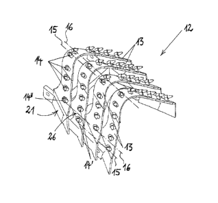
Figure 1 shows a perspective view of a bucket 12 which can be
arranged on the base body 10 of a bucket wheel 1, as is shown
in a perspective view in figure 3. The bucket 12 has a bucket
frame 21 on which, for example, four bucket cutters 13 are
arranged. The bucket cutters 13 extend transversely over the
bucket frame 21 in an arcuate shape and cutting teeth 14 are
arranged on the bucket cutters 13.
CA 02904147 2015-09-04
- 14 -
Two of the bucket cutters 13 which are shown are fitted in the
same way in each case with cutting teeth 14, and adjacent
bucket cutters 13 each have different arrangements of cutting
teeth 14. According to the invention, in this context the
cutting teeth 14 which are accommodated on bucket cutters 13
adjacent to one another are arranged at least offset with
respect to one another, with the result that the latter can be
moved on orbits 15 and 16 which are offset in the direction of
the bucket wheel rotational axis, if the bucket wheel 1 rotates
about its bucket wheel rotational axis 11. For example, two
first orbits 15 and two second orbits 16, which are each formed
by connecting lines between cutting teeth 14 which are not
arranged on adjacent bucket cutters 13, are shown for a number
of cutting teeth 14. As a result of the fact that an offset is
present between the orbits 15 and 16 of the cutting teeth 14,
the cutting teeth 14 which are arranged on subsequent bucket
cutters 13 run through respective tooth gaps 26 of preceding
bucket cutters 13. This effect is shown by way of example with
the cutting teeth 14' and 14", and the tooth gap 26 is shown
between the cutting teeth 14' which are together accommodated
on a preceding bucket cutter 13, and the tooth gap 26 is
subsequently passed through with the cutting tooth 14" on the
subsequent bucket cutter 13.
Figure 2 shows a plan view of a detail of the bucket wheel 1
with a sequence of a plurality of bucket cutters 13, which is
shown in the rotational direction R. The view shows the arcuate
configuration of the bucket cutters 13, on the outside of which
the cutting teeth 14 are mounted. The arcuate shape of the
bucket cutters 13 is determined by two side sections 19 which
run together toward a bucket center 18. The side sections 19
have a direction of extent which encloses an attitude angle a
with the bucket wheel rotational axis 11, which attitude angle
a is not represented to scale by the projection illustration.
The direction of extent is formed, for example, by a connecting
CA 02904147 2015-09-04
- 15 -
line between the cutting teeth 14 accommodated on a bucket
cutter 13, in the region of the side sections 19. The angle
between the projected direction of extent of the side sections
19 and the bucket wheel rotational axis 11 is characterized by
a and has a value of, for example, 502. In conjunction with
figure 4 it becomes clear here that the ratio between the
bucket cutter depth t and the bucket cutter width b has a low
value, since the arcuate basic shape of the bucket cutters 13
is made very flat compared to a U-shaped bucket 12. The ratio
between the bucket cutter depth t and the bucket cutter width b
is, for example, only 0.2 to 0.4 here.
In the plan view of the detail of the bucket wheel 1 which is
shown it is also apparent that the positions of the cutting
teeth 14 on successive bucket cutters 13 in the direction of
the bucket wheel rotational axis 11 are arranged offset with
respect to one another in the rotational direction R. Overall,
two different ways of equipping with teeth are shown, and for
example a cutting tooth 14 lies on every second bucket cutter
13 on the bucket center 18, and on every second bucket cutter
13 the cutting teeth 14 are accommodated laterally offset with
respect to the bucket center 18.
Figure 3 shows approximately half of the bucket wheel 1, and it
is apparent that a large number of bucket cutters 13 are
accommodated on the base body 10 of the bucket wheel 1. In this
context, a plurality of bucket cutters 13 are accommodated on
respective bucket frames 21, and adjacent bucket cutters 13
each have cutting teeth 14 with different equipment positions.
The base body 10 of the bucket wheel 1 has two annular carriers
27 which run parallel to one another and between which
transverse beams 28 extend at uniform intervals. In the annular
spaces which are formed in this way, bucket shells 24 are
located, by means of which the deposited material is conveyed
CA 02904147 2015-09-04
- 16 -
into the inner side of the bucket wheel 1, in order finally to
arrive at a transportation belt of a bucket wheel excavator.
Figure 4 shows a cross-sectional view of the bucket wheel 1
with the base body 10, on whose circumference bucket cutters 13
are arranged, and bucket shells 24 are shown on the inside.
The bucket cutters 13 have a bucket cutter width b which is
determined essentially by the maximum width with which the
outer cutting teeth 14 are accommodated on the bucket cutters
13. In addition, the bucket cutters 13 have a bucket cutter
depth t which is determined by the radial distance between the
innermost and outermost cutting teeth 14 on the bucket cutters
13. The bucket wheel 1 extends about the bucket wheel
rotational axis 11 and has a cutting circle diameter 20 which
is defined by the maximum diameter of the bucket wheel 1.
In figure 5, a section of the bucket wheel 1 is shown in a side
view in which it is apparent that respective buckets 12 have,
for example, four bucket cutters 13. The buckets 12 have bucket
frames 21 on which the bucket cutters 13 with the cutting teeth
14 are accommodated. The bucket frames 21 are arranged by means
of bolt connections 29 on the annular carrier 27, and each
bucket 12 has a bucket shell 24 which is preceded by four
bucket cutters 13 in the rotational direction R. A bucket
cutter 13 forms here a main bucket cutter 13 and is connected
to the bucket shell 24.
Figure 6 shows the view of a bucket 12 from the underside, and
a bucket frame 21 can therefore be seen, four bucket cutters 13
being accommodated on said bucket frame 21. The bucket frame 21
has two longitudinal beams 22 which run approximately parallel
to one another and between which a transverse beam 23 extends,
with the result that the bucket frame 21 has essentially a H
CA 02904147 2015-09-04
- 17 -
shape. The bucket cutters 13 extend here in an approximately
arcuate shape between the two longitudinal beams 22.
Figure 7a shows a schematic view of the tooth engagement of a
plurality of cutting teeth 14 which are arranged on a bucket 12
according to the prior art, wherein the arrangement of the
cutting teeth 14 of a plurality of cutters 12 on a bucket wheel
with respect to one another are the same in each case. Each
cutting tooth 14 releases an assigned digging cross section 17
from the material composite 25 here, wherein the digging cross
sections 17 each lie adjacent and approximately at the same
height with respect to one another in a row. The bucket 12 is
moved laterally against the material composite 25 here in the
bucket wheel rotational axis 11 shown, as indicated by a
direction arrow. As a result, only cutting teeth 14 which are
arranged on the side section 19 of the bucket 12 enter into
engagement with the material composite 25. For example, eight
cutting teeth 14 per bucket 12 are arranged at the same height
as one another on the side section 19.
Figure 7b shows a bucket 12 with two bucket cutters 13, with
the result that the eight cutting teeth 14 according to figure
7a are distributed between the two bucket cutters 13.
Consequently, each bucket cutter 13 now has only four cutting
teeth 14 which are arranged on the bucket cutter 13 at a
respectively larger distance from one another compared to the
arrangement according to figure 7a. The cutting teeth 14 on the
exemplary two bucket cutters 13 are arranged offset with
respect to one another, with the result that cutting teeth 14
which are accommodated on a common bucket cutter 13 remove
digging cross sections 17 which are not adjacent to one another
from the material composite 25. Simply the engagement of the
cutting teeth 14 on the subsequent bucket cutter 13 causes the
further digging cross sections 17 which are located between the
initially removed digging cross sections 17 to be removed, with
,
CA 02904147 2015-09-04
- 18 -
the result that each cutting tooth 14 is assigned a defined
digging cross section 17 which is of a respective size where a
limitation of the maximum chunk size is achieved. In particular
it is ensured that the cutting forces which act on the cutting
teeth 14 do not become too large and the cutting teeth 14 can
be at a sufficient distance from one another.
Figures 8 and 9 show by way of example digging cross sections
17 such as can be removed from the material composite 25 if
three (figure 8) or four (figure 9) bucket cutters 13 with
respectively the different cutting tooth equipment are
provided.
The invention is not limited in its implementation to the
preferred exemplary embodiment specified above. Instead, a
number of variants are conceivable which make use of the
illustrated solution even in the case of embodiments which are
of a basically different type. All of the features and/or
advantages which proceed from the claims, the description or
the drawings, including structural details or spatial
arrangements, can be essential to the invention either per se
or in a wide variety of combinations.
CA 02904147 2015-09-04
- 19 -
List of Reference Symbols
1 Bucket wheel
Base body
5 11 Bucket wheel rotational axis
12 Bucket
13 Bucket cutter, main bucket cutter
14 Cutting tooth
14' Cutting tooth
10 14" Cutting tooth
First orbit
16 Second orbit
17 Digging cross section
18 Bucket center
15 19 Side section
Cutting circle diameter
21 Bucket frame
22 Longitudinal beam
23 Transverse beam
20 24 Bucket shell
Material composite
26 Tooth gap
27 Annular carrier
28 Transverse beam
25 29 Bolt connection
Bucket cutter width
Bucket cutter depth
a Attitude angle
R Rotational direction