Note: Descriptions are shown in the official language in which they were submitted.
CA 02904409 2015-09-04
WO 2014/143670 PCT/US2014/027674
LASER SHAVING
CROSS-REFERENCE TO RELATED APPLICATIONS
[0001] The present application claims the priority benefit of U.S.
Provisional Application No. 61/801,162, filed March 15, 2013, and U.S.
Application
No. 14/210,248, filed March 13, 2014, the entirety of each of which is hereby
incorporated by reference herein.
BACKGROUND
Field
[0002] The present disclosure generally relates to devices and methods
for cutting or processing matter using light, including but not limited to
shaving using
laser light.
Description of the Related Art
[0003] Shaving is most commonly performed using razors having one or
more metal blades. However, razors can irritate and damage the user's skin.
Razors are also limited to removing hair at the surface of the skin, which
results in
the hair becoming visible again in a relatively short time period. Various
laser
devices are also available for hair removal. However, laser hair removal
devices
and methods typically involve using laser light to destroy the hair follicle
below the
skin surface for permanent or semi-permanent hair removal. Such devices and
methods are typically more dangerous, expensive, not suitable for home use,
and
often do not provide effective cutting of lighter colored hair.
SUMMARY
[0004] The present disclosure describes devices and methods for cutting
matter, including but not limited to shaving hair. In some embodiments, a
shaving
device uses electromagnetic radiation or light (e.g., laser or other light
energy) to cut
or damage one or more hair shafts. At least one surface of at least one fiber
or a
-1-
CA 02904409 2015-09-04
WO 2014/143670 PCT/US2014/027674
light guide can emit light towards at least one hair shaft. In some
embodiments, the
fiber or light guide is configured to couple light into at least one hair
shaft through at
least one light transmitting surface of the fiber or light guide. Such devices
can
couple light into one or more hair shafts with or without a coupling enhancing
medium, such as any such coupling medium described below, or others. Devices
according to the present disclosure are effective, efficient, cost effective,
and safe
for home use.
[0005] In one embodiment, a device configured to cut hair using laser
light
includes a handle portion and a shaving portion. The handle portion includes a
battery and a laser light source. The laser light source is coupled to and
configured
to receive power from the battery. The laser light source is also configured
to
generate laser light having a wavelength selected to target a predetermined
chromophore to effectively cut a hair shaft. The shaving portion includes a
support
and a single fiber optic supported by the support. The fiber optic has a
proximal
end, a distal end, an outer wall, and a cutting region positioned towards the
distal
end and extending along a portion of the side wall. The fiber optic is
positioned to
receive the laser light from the laser light source at the proximal end,
conduct the
laser light from the proximal end toward the distal end, and emit the light
out of the
cutting region and toward hair when the cutting region is brought in contact
with the
hair.
[0006] The fiber optic may be further configured to prevent light from
being
emitted from the cutting region when the cutting region is not in contact with
the hair.
The support may be T-shaped. The support may include a channel configured to
receive the fiber optic, and the fiber optic may be positioned within the
channel. In
some embodiments, the wavelength is within one or more ranges selected from a
group consisting of: 380 nm to 480 nm, 380 nm to 500 nm, 400 nm to 500 nm,
2500
nm to 3500 nm, 2950 nm to 3050 nm, and 2700 nm to 3500 nm.
[0007] In some embodiments, the shaving portion is removably coupled to
the handle portion, the fiber optic is removably coupled to the support, or
both. The
predetermined chromophore may be selected from the group consisting of: sebum,
a fatty acid, phytoshingosine, ceramide, cholesterol, cholesterol sulfate, and
-2-
CA 02904409 2015-09-04
WO 2014/143670 PCT/US2014/027674
cholesterol oleate. In some embodiments, the device also includes an optic
configured to direct the laser light from the laser light source to the
proximal end of
the fiber optic.
[0008] In some embodiments, the fiber optic has a diameter in the range
of about 4 microns to about 1000 microns. The device may also include a
reflector
positioned at the distal end of the fiber optic and configured to reflect
light towards
the fiber optic proximal end. The device may also include a vacuum source
coupled
to the support and configured to provide aspiration near the cutting region.
[0009] In some embodiments, the fiber optic includes a core and a
cladding that surrounds the core along the fiber optic length, except at the
cutting
region. The cutting region may have a radius of curvature that is different
than
radius of curvature of the fiber optic near its proximal end. In some
embodiments, a
cross-sectional shape of the fiber optic at the cutting region is wedge-
shaped. In
some embodiments, the fiber optic tapers in diameter along the cutting region.
[0010] In yet another embodiment, a method of shaving hair with laser
light includes providing a device configured to cut hair and directing laser
light from
the device's light source, through its cutting region, and towards a shaft of
the hair to
cut the hair. The device includes a handle portion and a shaving portion. The
handle portion includes a battery and a laser light source. The laser light
source is
coupled to and configured to receive power from the battery. The laser light
source
is also configured to generate laser light having a wavelength selected to
target a
predetermined chromophore to effectively cut a hair shaft.
[0011] The shaving portion includes a support and a single fiber optic
supported by the support. The fiber optic has a proximal end, a distal end, an
outer
wall, and a cutting region positioned towards the distal end and extending
along a
portion of the side wall. The fiber optic is positioned to receive the laser
light from
the laser light source at the proximal end, conduct the laser light from the
proximal
end toward the distal end, and emit the light out of the cutting region and
towards
the hair when the cutting region is brought in contact with the hair.
[0012] The method may also include preventing light from being emitted
from the cutting region when the cutting region is not in contact with the
hair. The
-3-
CA 02904409 2015-09-04
WO 2014/143670 PCT/US2014/027674
method may also include removably coupling: (1) the shaving portion to the
handle
portion, (2) the fiber optic to the support, or (3) both. The wavelength may
be within
one or more ranges selected from a group consisting of: 380 nm to 480 nm, 380
nm
to 500 nm, 400 nm to 500 nm, 2500 nm to 3500 nm, 2950 nm to 3050 nm, and
2700 nm to 3500 nm.
[0013] For purposes of summarizing the disclosure and the advantages
achieved over the prior art, certain objects and advantages are described
herein. Of
course, it is to be understood that not necessarily all such objects or
advantages
need to be achieved in accordance with any particular embodiment. Thus, for
example, those skilled in the art will recognize that the disclosure may be
embodied
or carried out in a manner that achieves or optimizes one advantage or group
of
advantages as taught or suggested herein without necessarily achieving other
objects or advantages as may be taught or suggested herein. All of these
embodiments are intended to be within the scope of the disclosure herein.
These
and other embodiments will become readily apparent to those skilled in the art
from
the following detailed description having reference to the attached figures,
the
disclosure not being limited to any particular disclosed embodiment(s).
BRIEF DESCRIPTION OF THE DRAWINGS
[0014] These and other features, aspects and advantages of the present
disclosure will be described with reference to the following drawings, which
are
illustrative but should not be limiting of the present disclosure.
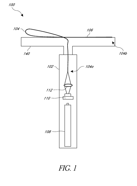
[0015] Figure 1 illustrates an example embodiment of a laser shaving
device;
[0016] Figure 2 illustrates another example embodiment of a laser
shaving
device;
[0017] Figure 3 illustrates another example embodiment of a laser
shaving
device resembling a straight razor;
[0018] Figure 4 illustrates a fiber portion of a laser shaver coupling
light
into a hair shaft; and
-4-
CA 02904409 2015-09-04
WO 2014/143670 PCT/US2014/027674
[0019]
Figure 5 illustrates a cross-sectional view of another embodiment
of a fiber at its cutting region.
DETAILED DESCRIPTION
[0020]
Although certain embodiments and examples are described below,
those of skill in the art will appreciate that the disclosure extends beyond
the
specifically disclosed embodiments and/or uses and obvious modifications and
equivalents thereof. Thus, it is intended that the scope of the disclosure
herein
should not be limited by any particular embodiments described below.
[0021] Hair
shafts can be severed with high intensity light via absorption
heating and burning and/or melting of the shaft. Some optical shaving devices
based on this mechanism have been envisioned as an alternative to shaving with
razors or laser hair removal. Some such devices include a plurality of optical
fibers
and are used to cut hair by coupling light into one end of the optical fibers
and
emitting the light out of the opposite end of the optical fibers and in a
direction
parallel to their longitudinal axes. One problem with using a plurality of
optical fibers
in this way is the increased loss of light into the cross-sectional area of
the claddings
of the multiple fibers. Light energy is lost in the cladding of a fiber as
light travels
through it, and therefore, more fiber optics results in more light energy
loss. In
addition, when coupling light from a single light source into a cross-
sectional surface
(e.g., the proximal end) of a plurality of fibers (e.g., a fiber-optic
bundle), an
additional problem is fraction losses into the spaces between the fibers, e.g.
in the
case of round fibers that are bundled together.
[0022] Devices and methods according to the present disclosure
advantageously overcome these problems and disadvantages associated with
cladding cross-sectional losses and/or fraction losses, resulting in a more
efficient
device. The techniques described herein advantageously allow the devices to be
smaller, lighter, and/or less costly to manufacture. In
addition, in some
embodiments, a single light source is coupled into a single fiber-optic
conduit. The
single fiber-optic conduit is configured to emit light out of a predetermined
area
along the side of the fiber's outer wall, as discussed in greater detail
below. The
-5-
CA 02904409 2015-09-04
WO 2014/143670 PCT/US2014/027674
side of the fiber's outer wall may be conditioned or configured in a manner
that light
can only escape out of the side of the fiber's outer wall surface when the
outer wall
surface is brought into contact with hair. In such cases, intense, energy-
focused
light is emitted only at such contact locations. This side-firing, focusing
effect
advantageously results in being able to effectively cut hair (and more
generally, to
remove matter) using less energy. Therefore, in some embodiments, an efficient
shaving device may include a battery powered, hand-held device. In addition,
because light is only emitted out of the side of the fiber when in contact
with hair (or
other targeted matter), the device is safer than devices that continuously
emit light
out of their distal ends when activated. In addition, the light exiting a side-
firing
fiber-optic shaving device exits the fiber-optic at a larger divergence angle
than an
end-firing fiber-optic. Therefore, because of such larger divergence angle,
the side-
firing fiber-optic shaving device is safer than end-firing devices, as the
light from a
side-firing device will diverge quicker and become weaker in intensity and
fluence
(power and energy per area) over distance.
[0023] Additionally, to damage and/or cut one or more hair shafts with
light, at least some of the light energy is absorbed by the hair shaft and
converted
into heat or induce a bond breaking mechanism. There are three chromophores in
hair that substantially absorb light ¨ melanin, keratin, and water. Keratin
and water
have absorption peaks at around 3000 nm. Melanin has an absorption peak around
300 nm, but remains relatively flat, decreasing almost linearly (on a
logarithmic
scale) to about 3000 nm. Darker hair, for example, black and brown hair,
contains
melanin and can be damaged or cut by sufficient amounts of ultraviolet (UV),
visible
(VIS), near infrared (NI R), and many infrared (IR) wavelengths. Previous
conceptual
models, devices, and methods have typically used laser diodes emitting light
having
a wavelength of about 810 nm to cut or damage the hair. Light having a
wavelength
about 600 nm is advantageously not absorbed by blood or not absorbed by blood
to
a large extent, which helps reduce the risk of adverse effects to the patient,
as light
having a wavelength above about 600 nm is not absorbed by hemoglobin. Some
previous devices and methods have attempted to use flash lamps as a light
source;
-6-
CA 02904409 2015-09-04
WO 2014/143670 PCT/US2014/027674
however, these have often been impractical for coupling the light into a
delivery
system.
[0024]
However, lighter hair, for example, white and blonde hair, has little
or no melanin; therefore, previous devices and techniques attempted to cut
light hair
by targeting water or keratin. Hair normally contains about 12% water. In some
cases, when there is no melanin or an insufficient amount of melanin, N IR
and/or IR
light can be used and absorbed by water to attempt to cut or damage hair.
However, when targeting water, if the fluence of the light is not initially
sufficient, the
water evaporates from the hair shaft and therefore cannot be used in a second
attempt to cut or damage the hair shaft. Surprisingly, white light with or
without UV
light can damage or cut light, for example, white or blonde, hair.
[0025] In
some embodiments, devices and methods of the present
disclosure use one or more of purple (about 400 nm or in the range of about
380 nm
to about 480 nm), blue, and/or blue-green light having wavelengths in the
range of
about 380 nm to about 500 nm or about 400 nm to about 500 nm to damage or cut
hair. In some embodiments, light having a wavelength of about 3000 nm is used
to
damage or cut hair. Surprisingly, light in these ranges is capable of damaging
or
cutting light hair, for example, even white and blonde hair. These wavelengths
can
be selected to target previously unknown chromophores, for example, sebum from
the hair follicle. In some embodiments, the wavelengths are selected to target
one
or more fatty acid(s), phytoshingosine, ceramide, cholesterol, cholesterol
sulfate,
and/or cholesterol oleate. In some embodiments, the light is selected to
target a
fatty layer of the hair, on an outer surface of the hair, in the hair, and/or
between
keratin flakes of the hair. In some embodiments, a user can apply an extrogen
chromophore to the hair, the shaving device, or both prior to shaving with any
of the
devices or according to any of the methods described herein. The extrogen
chromophore can be selected to target any desired wavelength(s). These
chromophores can advantageously exhibit greater absorption at these
wavelengths
that previously known chromophores.
Additionally, hair typically contains air
between layers of keratin. The air pockets can scatter light directed at the
hair and
increasingly scatter the light as wavelength decreases.
Increased scattering
-7-
CA 02904409 2015-09-04
WO 2014/143670 PCT/US2014/027674
lengthens the path of the light in the hair shaft, which increases the
probability of the
light being absorbed by the hair shaft. The shorter wavelengths in the blue
and
blue-green range can therefore also cause more scattering, which increases the
path length and probability of absorption.
[0026] In some embodiments, a shaving device according to the present
disclosure can include a single side firing waveguide, such as a laser fiber
optic,
housed in or supported by a mechanical support. In other embodiments, the
shaving device includes more than one fiber. Additionally, in some
embodiments,
light can be emitted from an end of the waveguide or fiber instead of or in
addition to
a side.
[0027] An example embodiment of a laser shaver 100 is shown in Figure
1. The shaver 100 includes a handle 102 and a support 140 that supports an
optical
waveguide, for example, an optical fiber 104, coupled to and extending from
the
handle 102. The waveguide can be a fiber, a hollow light guide, a liquid light
guide,
or any other light guide. The handle 102 generally includes a power source
108, at
least one light source 110, for example, a diode laser along with any laser
driver
boards needed, and one or more optics 112. In some embodiments, the light
source can be or include a Xenon flash lamp. The light source can be
configured to
emit various wavelengths of light, for example, between about 2500 nm to about
3500 nm, for example, about 3000 nm, or between about 400 nm to about 500 nm.
In some embodiments, the light source can be configured to emit UVA light, UVB
light, light that is at least about 20% UVA, light that is at least about 20%
in the 400
nm to 500nm range, light that is at least about 20% in the 2700 nm-3500 nm
range,
light that is at least about 20% in the 3000 nm range, light that includes UVA
light,
light that includes light in the range of 380 nm to 480 nm range, light that
includes
light in the 400 nm to 500 nm range, light that includes light in the 2700 nm
to 3500
nm range, light that is substantially in the 400 nm to 500 nm range, light
that is
substantially in the 2700 nm to 3500 nm range, and/or light that is
substantially
about 3000 nm or about 3000 nm 500 nm in wavelength. In some embodiments,
light sources of different wavelengths can be used with a single fiber 104. In
some
-8-
CA 02904409 2015-09-04
WO 2014/143670 PCT/US2014/027674
embodiments, light sources of different wavelengths can be coupled into
multiple
fibers or other light guides.
[0028] The power source 108 is electrically coupled to the light source
110
to power the light source 110. In use, the light source 110 emits light, which
is
directed to the one or more optics 112. The one or more optics 112 are
configured
to couple the light from the light source 110 into the proximal end 104a of
the fiber
104. The one or more optics 112 can be a lens or lens system or one or more
reflectors. In some embodiments, a separate optic is not necessary, and light
can
be coupled into the waveguide by proximity or direct or indirect contact. In
any
embodiment according to the present disclosure, the light can be laser light,
coherent light, and/or at least one part of non-collimated light. Part or all
of the
shaver 100 can be waterproof or water resistant. In some embodiments, the
light
source 110 can be located outside the handle 102, for example in a base unit.
The
base unit can be electrically and/or optically connected to the handle 102 by
an
electrical conductor or a light conductor. For example, a fiber or umbilicus
can
transfer the light from the base unit to the handle 102.
[0029] Figure 4 illustrates a partial view of the fiber 104. The fiber
104 can
have various cross-sectional shapes, for example, round as shown in the
illustrated
embodiment. As shown, the fiber 104 includes a core 114 and an outer cladding
116 surrounding the core 114. In some embodiments, the fiber core 114 has a
diameter in the range of about 4 microns to about 1000 microns. In some
embodiments, the fiber core 114 has a diameter between 0.5 mm and 2 mm. In
use, light rays 118 propagate along the fiber 104 from the proximal end 104a
toward
the distal end 104b. The light rays 118 are confined within the core 114 due
to the
core's higher index of refraction compared to the lower index of refraction of
the
cladding 116. The fiber 104 includes an aperture or a cutting or light-
emitting
surface 106 at or near the distal end 104b of the fiber 104. The cutting
surface 106
can be shaped to a line having a length of between about 2 mm and about 200
mm.
In some embodiments, the cutting surface 106 includes a plurality of optical
waveguides or fibers. For example, a single fiber 104 coupled to the handle
102
can couple to a plurality of fibers. In other embodiments, a plurality of
fibers or other
-9-
CA 02904409 2015-09-04
WO 2014/143670 PCT/US2014/027674
waveguides can extend from the handle 102. In some embodiments, the cutting
surface 106 is positioned along the length of the fiber optic 104, and spaced
from
the fiber optic's distal end 104b. For example, the entire cutting surface 106
can be
spaced a distance from the fiber optic's distal end 104b. The fiber optic 104
may be
configured such that the cutting surface 106 does not extend to the fiber's
distal end
104b.
[0030] Figure 5 illustrates a cross-sectional view of another
embodiment
of a fiber 104 at its cutting region. The fiber 104 includes a core 114 and an
outer
cladding 116 that partially surrounds the core 114. The outer surface 130 of
the
core 114 includes a contoured portion 132. In the illustrated embodiment, the
contoured portion 132 is concave, although in other embodiments, the contoured
portion 132 can be convex, planar, pointed, wedge-shaped, etc. The fiber 104
and
the cutting region can be formed by drawing, extruding, casting, or equivalent
technique. The curvature of the contoured portion 132 can provide a lensing
effect
to assist in directing light out of the side of the fiber 104 and into the
hair shaft 134
by forming an optical focusing region 136 within the hair shaft 134. The
contoured
portion 132 may be shaped to conform to the hair's outside radius and focus
energy
inside the hair shaft 134 while bending the hair shaft 134. In some
embodiments,
the contoured portion 132 is covered at least partially with a coating. For
example, a
portion of the cladding 116 may be removed from at least a portion of the
fiber 104
to expose a portion of the core 114, e.g., on a side of the fiber along its
length, and
the exposed portion may subsequently be covered by a coating. The coating may
be referred to as a "re-cladding." The coating may include any of the coating
described above, including but not limited to a clear resin, an organic
grease,
silicone, petroleum gel, clear PTFE, clear ePTFE, clear rubber, clear RTV,
etc. In
some embodiments, the coating may be reflective, transmitting, non-reflective,
lubricous, and/or configured to grab onto hair.
[0031] In some embodiments, the fiber 104 can include a mirror or fiber
re-circulator (not shown) at or near a distal end 104b to reflect the light
traveling
within the fiber 104 to increase light output and efficiency. The mirror can
return and
help direct at least part of any non-consumed light to the cutting surface
106. In
-10-
CA 02904409 2015-09-04
WO 2014/143670 PCT/US2014/027674
some embodiments, one or more optical reflective coatings are applied to at
least
part of the fiber 104 to help recycle radiation within the fiber 104 and
improve
efficiency.
[0032] In some embodiments, the shaver 100 also includes a vacuum (not
shown), with an optional filter, positioned near or alongside the fiber 104.
The
vacuum can be configured to remove smoke that may result from burning the
hair.
[0033] The shaver 100 can have various configurations, for example as
shown in Figures 1-3. The embodiments of Figures 1 and 2 have substantially
the
same handle 102 configuration. However, the fibers 104 and/or supports 140 of
the
embodiments of Figures 1 and 2 have different shapes or configurations. The
fiber
104 and/or support 140 can have various shapes and configurations to improve
ease of use of the shaver 100. For example, the fiber 104 and/or support 140
can
be substantially linear, curved, or include both linear and curved segments.
The
fiber 104 and/or support 140 can be L shaped, S shaped, T-shaped, or any other
suitable shape. In some embodiments, the fiber 104 is held or at least
partially
contained by a mechanical support 140. Such a mechanical support 140 provides
greater strength and structure to the shaver 100 as a single fiber 104 alone
could be
too flexible to maintain a desired shape and could be more vulnerable to
damage.
In some embodiments, the shaver 100 can be configured to resemble a
traditional
bladed razor. In the embodiment of Figure 3, the shaver 100 is similar to a
straight
razor. In the illustrated embodiment, the shaver 100 includes a support
segment
120 that resembles the blade of a straight razor. The support segment 120 is
coupled to the handle 102 via a hinge or pivot 122. In some embodiments, the
support segment 120 is pivotally coupled to the handle 102 so that the shaver
100 is
foldable. The cutting surface 106 of the fiber 104 can be positioned along an
edge
of the support segment 120 so that the user can use the shaver 100 in a
similar
manner as he or she would use a straight razor. In other embodiments, the
shaver
100 can resemble a safety razor, and the cutting surface 106 can be positioned
where a blade would be in a traditional safety razor.
[0034] In some embodiments, the shaver 100 is disposable. In other
embodiments, the handle 102 is reusable, and the fiber 104 portion including
the
-11-
CA 02904409 2015-09-04
WO 2014/143670 PCT/US2014/027674
mechanical support 140 are disposable, similar to a safety razor having
disposable
cartridges. The fiber 104 portion can be removeably coupled to the handle 102
and
can be replaced after a number of uses. The proximal end 104a of the fiber 104
can include a connector configured to couple to a connector on the handle 102.
One or both of the connectors can be waterproof or water resistant. In some
embodiments, an intermediate waveguide can couple a disposable fiber 104
portion
to the handle 102.
[0035] In
some embodiments, the cutting surface 106 includes a portion of
the fiber 104 where the cladding 116 has been removed, for example as shown in
Figure 4. The cladding 116 can be removed via various methods, for example,
chemical and/or mechanical methods. Because air has a lower index of
refraction
than the core 114, the light rays 118 are still confined within the fiber 104.
The
cutting surface 106 of the shaver 100 must therefore be in contact with hair
10,
which has a higher index of refraction than the core 114, for light to be able
to
couple out of the fiber 104. For example, a fiber 104 having a silica core can
have
an index of refraction of about 1.47, whereas hair, which is made mostly of
keratin
with lipids, typically has an index of refraction of about 1.56. In other
words, little to
no light leaks out of or is emitted from the fiber 104 when the cutting
surface 106 is
not in contact with the hair or another object having a higher index of
refraction than
the core. This advantageously confines the laser radiation for safety reasons,
for
example, for eye safety, and improves the efficiency of the device as the
light
emitted is used for cutting hair rather than losing light to the room. When
the cutting
surface 106 is placed into contact with hair 10, the hair shaft begins to draw
the
radiation from the fiber 104, for example, via evanescent transfer of
radiation from
the fiber 104 to the hair shaft 10. In some embodiments, the cladding 116 is
only
removed from a portion of the circumference of the fiber 104 as shown in
Figure 4.
This advantageously reduces the risk of a user accidentally contacting another
portion of the body with a light emitting portion of the fiber 104. In
some
embodiments, the shaver 100 can include a sensor configured to detect contact
with
hair and the shaver 100 can be configured such that the light source 110 is
only
-12-
CA 02904409 2015-09-04
WO 2014/143670 PCT/US2014/027674
turned on or active when the cutting surface 106 is determined to be in
contact with
hair.
[0036] In
some embodiments, light is coupled out of the fiber 104 at the
cutting surface 106 by using a coating or coupling material, instead of or in
addition
to removal of the cladding 116. In some such embodiments, the cutting surface
106
does not have to be in contact with hair to emit light. For example, the
cutting
surface 106 can be processed with photolithography or etching to create a
surface
that allows light to exit the fiber 104. In some embodiments, a scatting
material can
be coupled, e.g., glued or adhered, to the cutting surface 106. In
some
embodiments, both the cladding 116 is removed from the cutting surface 106 and
the cutting surface 106 is further processed or a scattering material is
coupled to the
cutting surface 106. In some embodiments, one or more coatings are applied to
at
least part of the fiber 104 to enhance energy transfer to the hair shaft. Such
coating
may optionally be applied to the hair as well (or instead of applying such
materials to
the fiber 104). Any of a variety of coating or coupling materials may be used,
including but not limited to, any of the chromophores discussed herein,
petroleum
gel, a resin, silicone, room-temperature vulcanization silicone (RTV),
polytetrafluoroethylene (PTFE), expanded polytetrafluoroethylene (ePTFE), etc.
In
some embodiments, the fiber 104 or cutting surface 106 is shaped to optimize
radiation transfer to the hair. For example, a distal portion of the fiber 104
can be
tapered to change the angles of light being propagated within the fiber until
at least
some of the light couples out of the fiber 104.
[0037] In
some embodiments, the shaver 100 includes at least one light
front cross-section shaping optic that at least partially arranges coherent
light along
a line of between about 2 mm and about 200 mm. In some such embodiments, the
light passes directly from the light shaping optic to the hair. In other
embodiments,
the light passes through at least one more optic to be directed to the hair.
In some
embodiments, the light shaping optic is a waveguide or fiber that at least
partially
changes the shape of light emitted to a line having a length of between about
2 mm
and about 200 mm. In some embodiments, light from the light source is coupled
into at least one blade shaped optic that guides at least part of the light to
the hair.
-13-
CA 02904409 2015-09-04
WO 2014/143670 PCT/US2014/027674
The blade shaped optic can be a light guide and/or a light transmitter. The
blade
shaped optic can be detachable, consumable, and/or exchangeable.
[0038] For
eye safety and/or skin comfort and/or safety, the light is
preferably not emitted directly toward the hair, face, or other body parts. In
some
embodiments, the shaving device is configured to direct the light emitted in a
direction parallel or substantially parallel to the skin surface or at an
angle selected
such that the light does not substantially enter the skin and/or eyes. For
example,
the shaver 100 and cutting surface 106 can be configured such that light
incident on
the hair is aimed toward the hair at an angle in the range of about 45 , for
example, in the range of about 5 , 100, or 25 , to the surface of the
skin. In
some embodiments, the shaver 100 includes at least one sensor configured to
detect a broken fiber. For example, a sensor can be positioned at or near the
distal
end 104b of the fiber 104 and can detect the amount of light incident on the
sensor.
If little or no light is reaching the sensor at the distal end 104b, the fiber
104 may be
broken and allowing radiation to leak out, which can create a safety hazard.
Therefore, if the sensor detects little or no light reaching the distal end
104b, the
shaver 100 can turn off the light or power source.
[0039] When
cutting white (or light) hair with blue light, e.g., at about 403
nm, approximately twice the fluence (or energy level) is needed compared to
cutting
brown hair (for example, by targeting melanin). Increasing the power can
therefore
improve the efficacy of the devices and methods described herein in some
cases;
however, increasing the power can also increase the risk of adverse effects in
some
cases. In some embodiments, a shaving device as described herein includes one
ore more sensors configured to detect or gather data indicative of the
chromophore(s) present in the target hair. For example, upon contact with the
hair,
the device can emit light into the hair, and a sensor can detect the light
reflected to
allow the device to determine the wavelengths of light absorbed. In
some
embodiments, the sensor could be located in the handle of the device. In some
embodiments, the sensor can be a MEMS device that functions as a spectrometer
and is located on the portion of the device configured to emit light to and/or
contact
the hair. If the sensor detects and/or the device determines based on sensor
data
-14-
CA 02904409 2015-09-04
WO 2014/143670 PCT/US2014/027674
that the hair contains a sufficient amount of melanin, the device can reduce
the
energy level or power and/or adjust the wavelength of light emitted to target
a
predetermined chromophore (e.g., melanin). If the sensor detects and/or the
device
determines based on sensor data that the hair lacks sufficient melanin but
contains
sufficient sebum, the device can increase the energy level or power and/or
adjust
the wavelength emitted to target the sebum.
[0040] More than one device as described herein can be used
synchronously or in sequence to cut or damage hair.
[0041]
Although the devices and methods herein have been described
with respect to cutting or damaging hair, these devices and methods can be
used for
other applications, for example, surgery. The device or cutting surface 106
can be
shaped similar to a knife, surgical scalpel, or other cutting tool. In
some
embodiments, when using the device to cut tissue, the device can also act as a
coagulating and bleeding stopping means by means of the heat created by light
absorbed into the tissue. The light can be modulated and tuned to cut tissue
or
coagulate.
[0042] It
should be emphasized that many variations and modifications
may be made to the embodiments described herein, the elements of which are to
be
understood as being among other acceptable examples. All such modifications
and
variations are intended to be included herein within the scope of this
disclosure and
protected by the following claims. Further, nothing in the foregoing
disclosure is
intended to imply that any particular component, characteristic or process
step is
necessary or essential.
-15-