Note: Descriptions are shown in the official language in which they were submitted.
- 1 -
ROBOTIC ULTRASONIC SURGICAL DEVICE WITH ARTICULATING END EFFECTOR
TECHNICAL FIELD
[0001] The present disclosure generally relates to surgical devices, and
more particular to
surgical devices with articulating end effectors.
BACKGROUND
100021 A variety of surgical instruments include an end effector having a
blade element
that vibrates at ultrasonic frequencies to cut and/or seal tissue (e.g., by
denaturing
proteins in tissue cells). These instruments include piezoelectric elements
that convert
electrical power into ultrasonic vibrations, which are communicated along an
acoustic
waveguide to the blade element. Examples of such ultrasonic surgical
instruments
include the HARMONIC ACE Ultrasonic Shears, the HARMONIC WAVE
Ultrasonic Shears, the HARMONIC FOCUS Ultrasonic Shears, and the HARMONIC
SYNERGY Ultrasonic Blades, all by Ethicon Endo-Surgery, Inc. of Cincinnati,
Ohio.
Further examples of such devices and related concepts are disclosed in U.S.
Pat. No.
5,322,055, entitled "Clamp Coagulator/Cutting System for Ultrasonic Surgical
Instruments," issued June 21, 1994, U.S. Pat. No. 5,873,873, entitled
"Ultrasonic Clamp
Coagulator Apparatus Having Improved Clamp Mechanism," issued February 23,
1999,
U.S. Pat. No. 5,980,510, entitled "Ultrasonic Clamp Coagulator Apparatus
Having
Improved Clamp Arm Pivot Mount," filed October 10, 1997, U.S. Pat. No.
6,325,811,
entitled "Blades with Functional Balance Asymmetries for use with Ultrasonic
Surgical
Instruments," issued December 4, 2001, U.S. Pat. No. 6,783,524, entitled
"Robotic
Surgical Tool with Ultrasound Cauterizing and Cutting Instrument," issued
August 31,
2004; U.S. Pub. No. 2006/0079874, entitled "Tissue Pad for Use with an
Ultrasonic
Surgical Instrument," published April 13, 2006, U.S. Pub. No. 2007/0191713,
entitled
"Ultrasonic Device for Cutting and Coagulating," published August 16, 2007,
U.S. Pub.
No. 2007/0282333, entitled "Ultrasonic Waveguide and Blade," published
December 6,
2007, U.S. Pub. No. 2008/0200940, entitled "Ultrasonic Device for Cutting and
Coagulating," published August 21, 2008, U.S. Pub. No. 2010/0069940, entitled
Date Recue/Date Received 2021-02-19
- 2 -
"Ultrasonic Device for Fingertip Control," published March 18, 2010, and U.S.
Pub. No.
2011/0015660, entitled "Rotating Transducer Mount for Ultrasonic Surgical
Instruments," published January 20, 2011, U.S. Pat. App. No. 13/538,588, filed
June 29,
2012, entitled "Surgical Instruments with Articulating Shafts,"; and U.S. Pat.
App. No.
13/657,553, filed October 22, 2012, entitled "Flexible Harmonic
Waveguides/Blades for
Surgical Instruments,". Additionally, some of the foregoing surgical tools may
include a
cordless transducer such as that disclosed in and U.S. Pat. App. No.
61/410,603, filed
November 5, 2010, entitled "Energy-Based Surgical Instruments,".
100031
In addition, a variety of surgical instruments include a shaft having an
articulation
section, providing enhanced positioning capabilities for an end effector that
is located
distal to the articulation section of the shaft. Examples of such devices
include various
models of the ENDOPATH endocutters by Ethicon Endo-Surgery, Inc., of
Cincinnati,
Ohio. Further examples of such devices and related concepts are disclosed in
U.S. Pat.
No. 7,380,696, entitled "Articulating Surgical Stapling Instrument
Incorporating a Two-
Piece E-Beam Firing Mechanism," issued June 3, 2008, U.S. Pat. No. 7,404,508,
entitled
"Surgical Stapling and Cutting Device," issued July 29, 2008, U.S. Pat. No.
7,455,208,
entitled "Surgical Instrument with Articulating Shaft with Rigid Firing Bar
Supports,"
issued November 25, 2008, U.S. Pat. No. 7,506,790, entitled "Surgical
Instrument
Incorporating an Electrically Actuated Articulation Mechanism," issued March
24, 2009,
U.S. Pat. No. 7,549,564, entitled "Surgical Stapling Instrument with an
Articulating End
Effector," issued June 23, 2009; U.S. Pat. No. 7,559,450, entitled "Surgical
Instrument
Incorporating a Fluid Transfer Controlled Articulation Mechanism," issued July
14,
2009, U.S. Pat. No. 7,654,431, entitled "Surgical Instrument with Guided
Laterally
Moving Articulation Member," issued February 2, 2010, U.S. Pat. No. 7,780,054,
entitled
"Surgical Instrument with Laterally Moved Shaft Actuator Coupled to Pivoting
Articulation Joint," issued August 24, 2010, U.S. Pat. No. 7,784,662, entitled
"Surgical
Instrument with Articulating Shaft with Single Pivot Closure and Double Pivot
Frame
Ground," issued August 31, 2010, and U.S. Pat. No. 7,798,386, entitled
"Surgical
Instrument Articulation Joint Cover," issued September 21, 2010.
Date Recue/Date Received 2021-02-19
-3-
100041 Some surgical systems provide robotic control of a surgical
instrument. With
minimally invasive robotic surgery, surgical operations may be performed
through a
small incision in the patient's body. A robotic surgical system may be used
with various
types of surgical instruments, including but not limited to surgical staplers,
ultrasonic
instruments, electrosurgical instruments, and/or various other kinds of
instruments, as
will be described in greater detail below. An example of a robotic surgical
system is the
DAVINCITM system by Intuitive Surgical, Inc., of Sunnyvale, California. By way
of
further example, one or more aspects of robotic surgical systems are disclosed
in the
following: U.S. Pat. No. 5,792,135, entitled "Articulated Surgical Instrument
For
Performing Minimally Invasive Surgery With Enhanced Dexterity and
Sensitivity,"
issued August 11, 1998; U.S. Pat. No. 5,817,084, entitled "Remote Center
Positioning
Device with Flexible Drive," issued October 6, 1998; U.S. Pat. No. 5,878,193,
entitled
"Automated Endoscope System for Optimal Positioning," issued March 2, 1999;
U.S.
Pat. No. 6,231,565, entitled "Robotic Arm DLUS for Performing Surgical Tasks,"
issued
May 15, 2001; U.S. Pat. No. 6,783,524, entitled "Robotic Surgical Tool with
Ultrasound
Cauterizing and Cutting Instrument," issued August 31, 2004; U.S. Pat. No.
6,364,888,
entitled "Alignment of Master and Slave in a Minimally Invasive Surgical
Apparatus,"
issued April 2, 2002; U.S. Pat. No. 7,524,320, entitled "Mechanical Actuator
Interface
System for Robotic Surgical Tools," issued April 28, 2009; U.S. Pat. No.
7,691,098,
entitled "Platform Link Wrist Mechanism," issued April 6, 2010; U.S. Pat. No.
7,806,891, entitled "Repositioning and Reorientation of Master/Slave
Relationship in
Minimally Invasive Telesurgery," issued October 5, 2010; and U.S. Pat. No.
7,824,401,
entitled "Surgical Tool With Writed Monopolar Electrosurgical End Effectors,"
issued
November 2, 2010.
100051 Additional examples of instruments that may be incorporated with a
robotic
surgical system are described in U.S. Pub. No. 2013/0012957, entitled
"Automated End
Effector Component Reloading System for Use with a Robotic System, published
January 10, 2013; U.S. Pub. No. 2012/0199630, entitled "Robotically-Controlled
Surgical Instrument with Force-Feedback Capabilities," published August 9,
2012; U.S.
Pub. No. 2012/0132450, entitled "Shiftable Drive Interface for Robotically-
Controlled
Surgical Tool," published May 31, 2012; U.S. Pub. No. 2012/0199633, entitled
"Surgical
Date Recue/Date Received 2021-02-19
- 4 -
Stapling Instruments with Cam-Driven Staple Deployment Arrangements,"
published
August 9, 2012; U.S. Pub. No. 2012/0199631, entitled "Robotically-Controlled
Motorized Surgical End Effector System with Rotary Actuated Closure Systems
Having
Variable Actuation Speeds," published August 9, 2012; U.S. Pub. No.
2012/0199632,
entitled "Robotically-Controlled Surgical Instrument with Selectively
Articulatable End
Effector," published August 9, 2012; U.S. Pub. No. 2012/0203247, entitled
"Robotically-
Controlled Surgical End Effector System," published August 9, 2012; U.S. Pub.
No.
2012/0211546, entitled "Drive Interface for Operably Coupling a Manipulatable
Surgical
Tool to a Robot," published August 23, 2012; U.S. Pub. No. 2012/0138660,
entitled
"Robotically-Controlled Cable-Based Surgical End Effectors," published June 7,
2012;
U.S. Pub. No. 2012/0205421, entitled "Robotically-Controlled Surgical End
Effector
System with Rotary Actuated Closure Systems," published August 16, 2012; U.S.
Pat.
App. No. 13/443,101, entitled "Control Interface for Laparoscopic Suturing
Instrument,"
filed April 10, 2012; and U.S. Provisional Pat. App. No. 61/597,603, entitled
-Robotically Controlled Surgical Instrument," filed February 10, 2012.
100061 While several surgical instruments and systems have been made and
used, the
surgical instruments and system may lack certain articulation characteristics
of their end
effectors. It is believed that no one prior to the inventors has made or used
the invention
described in the appended claims.
SUMMARY OF THE INVENTION
100071 In an aspect, an apparatus for operating on tissue is provided. The
apparatus
comprises: (a) an end effector, wherein the end effector comprises an
ultrasonic blade; (b)
a shaft assembly, wherein the end effector is disposed at a distal end of the
shaft
assembly, wherein the shaft assembly defines a longitudinal axis, wherein the
shaft
assembly includes an articulation section operable to deflect the end effector
away from
the longitudinal axis; and (c) an interface assembly, wherein the interface
assembly is
configured to drive the end effector, wherein the interface assembly
comprises: (i) a
base, wherein the base is configured to couple with a dock of a robotic
control system,
(ii) at least one eccentric cam, (iii) a plurality of drive shafts, wherein at
least one of the
drive shafts is operably coupled to the at least one eccentric cam to thereby
rotate the at
Date Recue/Date Received 2021-02-19
- 5 -
least one eccentric cam, wherein rotation of the at least one eccentric cam is
operable to
drive the articulation section, and (iv) a plurality of drive discs associated
with the
plurality of drive shafts, wherein the drive discs each comprise a respective
pair of pins,
wherein the pins are configured to couple with complementary drive features of
a robotic
control system.
[0008] In another aspect, an apparatus for operating on tissue is
provided. The apparatus
comprises: (a) an end effector, wherein the end effector comprises an
ultrasonic blade; (b)
a shaft assembly, wherein the end effector is disposed at a distal end of the
shaft
assembly, wherein the shaft assembly defines a longitudinal axis, wherein the
shaft
assembly includes an articulation section operable to deflect the end effector
away from
the longitudinal axis; (c) an interface assembly, wherein the interface
assembly is
configured to drive the end effector, wherein the interface assembly
comprises: (i) a
base, (ii) at least one eccentric cam operably coupled to the articulation
section, and (iii) a
plurality of drive shafts, wherein the drive shafts are rotatable relative to
the base,
wherein at least one of the drive shafts is operably coupled to the at least
one eccentric
cam to thereby rotate the at least one eccentric cam; and (d) a robotic
control system,
wherein the robotic control system comprises: (i) a robotic arm including a
dock,
wherein the base is configured to couple with the dock, wherein the dock
includes drive
features operable to couple with the drive shafts, and (ii) a user interface
assembly,
wherein the user interface assembly is operable to remotely control the drive
features.
[0009] In an embodiment, the shaft assembly comprises an acoustic
waveguide assembly,
and the waveguide assembly comprises: (i) a rigid waveguide portion, and (ii)
a flexible
waveguide portion, wherein the flexible waveguide portion extends through the
articulation section, wherein the flexible waveguide portion includes a
narrowed section
positioned proximal to the end effector and configured to provide flexing of
the flexible
waveguide portion, and the waveguide assembly is operable to transmit
ultrasonic
vibrations to the ultrasonic blade.
[00010] In an embodiment, the shaft assembly is rotatable relative to the
interface
assembly.
Date Recue/Date Received 2021-02-19
-6-
1000111 In an embodiment, a first drive shaft of the plurality of drive
shafts is rotatable to
rotate the shaft assembly relative to the interface assembly.
[00012] In an embodiment, the shaft assembly and the first drive shaft
include meshing
helical gears.
[00013] In an embodiment, the end effector further comprises a clamp arm,
wherein the
clamp arm is operable to pivot relative to the ultrasonic blade.
[00014] In an embodiment, a first drive shaft of the plurality of drive
shafts is rotatable to
pivot the clamp arm toward the ultrasonic blade.
[00015] In an embodiment, the shaft assembly comprises a translating member
coupled
between the first drive shaft and the clamp arm.
[00016] In an embodiment, the interface assembly further comprises: (i) an
eccentric cam
secured to the first drive shaft, and (ii) a rack coupled with the translating
member,
wherein the eccentric cam is operable to drive the rack proximally in response
to rotation
of the first drive shaft, to thereby pivot the clamp arm toward the ultrasonic
blade.
1000171 In an embodiment, the articulation section comprises a first
articulation band,
wherein the first articulation band is translatable relative to the shaft
assembly to deflect
the end effector away from the longitudinal axis.
[00018] In an embodiment, the articulation section further comprises a
second articulation
band, wherein the first articulation band is translatable relative to the
shaft assembly to
deflect the end effector away from the longitudinal axis in a first direction,
wherein the
second articulation band is translatable relative to the shaft assembly to
deflect the end
effector away from the longitudinal axis in a second direction.
1000191 In an embodiment, a first drive shaft of the plurality of drive
shafts is rotatable to
translate the first articulation band.
1000201 In an embodiment, the interface assembly further comprises: (i) an
eccentric cam
secured to the first drive shaft, and (ii) a pivoting arm coupled with the
first articulation
band, wherein the eccentric cam is operable to drive the pivoting arm
proximally in
Date Recue/Date Received 2021-02-19
- 7 -
response to rotation of the first drive shaft, to thereby deflect the end
effector away from
the longitudinal axis.
[00021] In an embodiment, the articulation section comprises a pair of
ribbed bodies,
wherein the first articulation band is apposed between the pair of ribbed
bodies.
[00022] In an embodiment, the base comprises a plurality of drive discs,
wherein the drive
discs are operable to rotate the drive shafts.
[00023] In an embodiment, the drive discs each comprise a respective pair
of pins,
wherein the pins are configured to couple with complementary drive features of
a robotic
control system.
BRIEF DESCRIPTION OF THE DRAWINGS
[00024] While the specification concludes with claims which particularly
point out and
distinctly claim this technology, it is believed this technology will be
better understood
from the following description of certain examples taken in conjunction with
the
accompanying drawings, in which like reference numerals identify the same
elements and
in which:
1000251 FIG. 1 depicts a block diagram of an exemplary robotic surgical
system;
1000261 FIG. 2 depicts a perspective view of an exemplary controller of the
system of
FIG. 1;
[00027] FIG. 3 depicts a perspective view of an exemplary robotic arm cart
of the system
of FIG. 1;
[00028] FIG. 4 depicts a perspective view of an exemplary surgical
instrument suitable for
incorporation with the system of FIG. 1;
[00029] FIG. 5 depicts a perspective view of the underside of the base
assembly of the
instrument of FIG. 4;
Date Recue/Date Received 2021-02-19
-8-
1000301 FIG. 6 depicts a perspective view of the end effector and shaft
assembly
articulation section of the instrument of FIG. 4;
[00031] FIG. 7 depicts an exploded view of the end effector and
articulation section of
FIG. 6;
[00032] FIG. 8 depicts a lateral cross-sectional view of the end effector
and articulation
section of FIG. 6;
[00033] FIG. 9 depicts a perspective view of the end effector and
articulation section of
FIG. 6, with an outer sheath omitted and with clamp pad features omitted;
[00034] FIG. 10 depicts a cross-sectional view of the end effector and
articulation section
of FIG. 6, taken along line 10-10 of FIG. 8;
[00035] FIG. 11 depicts a cross-sectional view of the end effector and
articulation section
of FIG. 6, taken along line 11-11 of FIG. 8;
[00036] FIG. 12 depicts a perspective view of the proximal end of the shaft
assembly of
the instrument of FIG. 4;
[00037] FIG. 13 depicts an exploded view of the proximal end of the shaft
assembly of the
instrument of FIG. 4;
[00038] FIG. 14 depicts a perspective view of the proximal end of the
instrument of FIG.
4, with the outer cover omitted;
[00039] FIG. 15 depicts a top plan view of the proximal end of the
instrument of FIG. 4,
with the outer cover omitted;
[00040] FIG. 16 depicts an exploded view of the proximal end of the
instrument of FIG. 4,
with the outer cover omitted;
[00041] FIG. 17 depicts a lateral cross-sectional view of a proximal
portion of the
proximal end of the instrument of FIG. 4, taken along line 17-17 of FIG. 15;
[00042] FIG. 18 depicts a lateral cross-sectional view of a distal portion
of the proximal
end of the instrument of FIG. 4, taken along line 18-18 of FIG. 15.
Date Recue/Date Received 2021-02-19
-9-
1000431 The drawings are not intended to be limiting in any way, and it is
contemplated
that various embodiments of the technology may be carried out in a variety of
other ways,
including those not necessarily depicted in the drawings. The accompanying
drawings
incorporated in and forming a part of the specification illustrate several
aspects of the
present technology, and together with the description serve to explain the
principles of
the technology; it being understood, however, that this technology is not
limited to the
precise arrangements shown.
DETAILED DESCRIPTION
[00044] The following description of certain examples of the technology
should not be
used to limit its scope. Other examples, features, aspects, embodiments, and
advantages
of the technology will become apparent to those skilled in the art from the
following
description, which is by way of illustration, one of the best modes
contemplated for
carrying out the technology. As will be realized, the technology described
herein is
capable of other different and obvious aspects, all without departing from the
technology.
Accordingly, the drawings and descriptions should be regarded as illustrative
in nature
and not restrictive.
1000451 It is further understood that any one or more of the teachings,
expressions,
embodiments, examples, etc. described herein may be combined with any one or
more of
the other teachings, expressions, embodiments, examples, etc. that are
described herein.
The following-described teachings, expressions, embodiments, examples, etc.
should
therefore not be viewed in isolation relative to each other. Various suitable
ways in
which the teachings herein may be combined will be readily apparent to those
of ordinary
skill in the art in view of the teachings herein. Such modifications and
variations are
intended to be included within the scope of the claims.
[00046] For clarity of disclosure, the terms "proximal" and "distal" are
defined herein
relative to a robotic surgical driver comprising a proximal housing having an
interface
that mechanically and electrically couples with a surgical instrument having a
distal
surgical end effector. The term "proximal- refers the position of an element
closer to the
robotic surgical driver housing and the term "distal" refers to the position
of an element
Date Recue/Date Received 2021-02-19
- 10 -
closer to the surgical end effector of the surgical instrument and further
away from the
housing.
[00047] I. Exemplary Robotic Surgical System Overview
[00048] FIG. 1 illustrates an exemplary robotic surgical system (10).
System (10)
comprises at least one controller (14) and at least one arm cart (18). Arm
cart (18) is
mechanically and/or electrically coupled to one or more robotic manipulators
or arms
(20). Each robotic arm (20) comprises one or more surgical instruments
(22) for
performing various surgical tasks on a patient (24). Operation of arm cart
(18), including
arms (20) and instruments (22), may be directed by a clinician (12) from
controller (14).
In some examples, a second controller (14'), operated by a second clinician
(12'), may
also direct operation of the arm cart (18) in conjunction with the first
clinician (12'). For
example, each of the clinicians (12, 12') may control different arms (20) of
the cart or, in
some cases, complete control of arm cart (18) may be passed between the
clinicians (12,
12'). In some examples, additional arm carts (not shown) may be utilized on
the patient
(24). These additional arm carts may be controlled by one or more of the
controllers (14,
14').
1000491 Arm cart(s) (18) and controllers (14, 14') may be in communication
with one
another via a communications link (16), which may be any suitable type of
wired and/or
wireless communications link carrying any suitable type of signal (e.g.,
electrical, optical,
infrared, etc.) according to any suitable communications protocol.
Communications link
(16) may be an actual physical link or it may be a logical link that uses one
or more
actual physical links. When the link is a logical link the type of physical
link may be a
data link, uplink, downlink, fiber optic link, point-to-point link, for
example, as is well
known in the computer networking art to refer to the communications facilities
that
connect nodes of a network.
[00050] FIG. 2 shows an exemplary controller (30) that may serve as a
controller (14) of
system (10). In this example, controller (30) generally includes user input
assembly (32)
having precision user input features (not shown) that are grasped by the
surgeon and
manipulated in space while the surgeon views the surgical procedure via a
stereo display
Date Recue/Date Received 2021-02-19
- 11 -
(34). The user input features of user input assembly (32) may include manual
input
devices that move with multiple degrees of freedom; and that include an
actuatable
handle for intuitively actuating tools (e.g., for closing grasping saws,
applying an
electrical potential to an electrode, etc). Controller (30) of the present
example also
includes an array of footswitches (38) providing additional control of arms
(20) and
instruments (22) to the surgeon. Display (34) may show views from one or more
endoscopes viewing the surgical site within the patient and/or any other
suitable view(s).
In addition, a feedback meter (36) may be viewed through the display (34) and
provide
the surgeon with a visual indication of the amount of force being applied to a
component
of instrument (22) (e.g., a cutting member or clamping member, etc.). Other
sensor
arrangements may be employed to provide controller (30) with an indication as
to
whether a staple cartridge has been loaded into an end effector of instrument
(22),
whether an anvil of instrument (22) has been moved to a closed position prior
to firing,
and/or some other operational condition of instrument (22).
[00051] FIG. 3 shows an exemplary robotic arm cart (40) that may serve as
of arm cart
(18) of system (10). In this example, arm cart (40) is operable to actuate a
plurality of
surgical instruments (50). While three instruments (50) are shown in this
example, it
should be understood that arm cart (40) may be operable to support and actuate
any
suitable number of surgical instruments (50). Surgical instruments (50) are
each
supported by a series of manually articulatable linkages, generally referred
to as set-up
joints (44), and a robotic manipulator (46). These structures are herein
illustrated with
protective covers extending over much of the robotic linkage. These protective
covers
may be optional, and may be limited in size or entirely eliminated in some
versions to
minimize the inertia that is encountered by the servo mechanisms used to
manipulate
such devices, to limit the volume of moving components so as to avoid
collisions, and to
limit the overall weight of cart (40).
1000521 Each robotic manipulator (46) terminates at an instrument platform
(70), which is
pivotable, rotatable, and otherwise movable by manipulator (46). Each platform
includes
an instrument dock (72) that is slidable along a pair of tracks (74) to
further position
instrument (50). Such sliding is motorized in the present example. Each
instrument dock
Date Recue/Date Received 2021-02-19
- 12 -
(72) includes mechanical and electrical interfaces that couple with an
interface assembly
(52) of instrument (50). By way of example only, dock (72) may include four
rotary
outputs that couple with complementary rotary inputs of interface assembly
(52). Such
rotary drive features may drive various functionalities in instrument (50),
such as is
described in various references cited herein and/or as is described in greater
detail below.
Electrical interfaces may establish communication via physical contact,
inductive
coupling, and/or otherwise; and may be operable to provide electrical power to
one or
more features in instrument (50), provide commands and/or data communication
to
instrument (50), and/or provide commands and/or data communication from
instrument
(50). Various suitable ways in which an instrument dock (72) may mechanically
and
electrically communicate with an interface assembly (52) of an instrument (50)
will be
apparent to those of ordinary skill in the art in view of the teachings
herein. It should
also be understood that instrument (50) may include one or more cables that
couple with
a separate power source and/or control unit, to provide communication of power
and/or
commands/data to/from instrument (50).
1000531 Arm cart (40) of the present example also includes a base (48) that
is movable
(e.g., by a single attendant) to selectively position arm cart (40) in
relation to a patient.
Cart (40) may generally have dimensions suitable for transporting the cart
(40) between
operating rooms. Cart (40) may be configured to fit through standard operating
room
doors and onto standard hospital elevators. In some versions, an automated
instrument
reloading system (not shown) may also be positioned in or near the work
envelope (60)
of arm cart (40), to selectively reload components (e.g., staple cartridges,
etc.) of
instruments (50).
1000541 In addition to the foregoing, it should be understood that one or
more aspects of
system (10) may be constructed in accordance with at least some of the
teachings of U.S.
Pat. No. 5,792,135; U.S. Pat. No. 5,817,084; U.S. Pat. No. 5,878,193; U.S.
Pat. No.
6,231,565; U.S. Pat. No. 6,783,524; U.S. Pat. No. 6,364,888; U.S. Pat. No.
7,524,320;
U.S. Pat. No. 7,691,098; U.S. Pat. No. 7,806,891; U.S. Pat. No. 7,824,401;
and/or U.S.
Pub. No. 2013/0012957. Still other suitable features and operabilities that
may be
Date Recue/Date Received 2021-02-19
- 13 -
incorporated into system (10) will be apparent to those of ordinary skill in
the art in view
of the teachings herein.
[00055] II. Exemplary Ultrasonic Surgical Instrument with Articulation
Feature
[00056] FIGS. 4-18 show an exemplary ultrasonic surgical instrument (100)
that may be
used as at least one instrument (50) within system (10). At least part of
instrument (100)
may be constructed and operable in accordance with at least some of the
teachings of
U.S. Pat. No. 5,322,055; U.S. Pat. No. 5,873,873; U.S. Pat. No. 5,980,510;
U.S. Pat. No.
6,325,811; U.S. Pat. No. 6,783,524; U.S. Pub. No. 2006/0079874; U.S. Pub. No.
2007/0191713; U.S. Pub. No. 2007/0282333; U.S. Pub. No. 2008/0200940; U.S.
Pub.
No. 2010/0069940; U.S. Pub. No. 2011/0015660; U.S. Pat. App. No. 13/538,588;
U.S.
Pat. App. No. 13/657,553; and/or U.S. Pat. App. No. 61/410,603. As described
therein
and as will be described in greater detail below, instrument (100) is operable
to cut tissue
and seal or weld tissue (e.g., a blood vessel, etc.) substantially
simultaneously. In other
words, instrument (100) operates similar to an endocutter type of stapler,
except that
instrument (100) provides tissue welding through application of ultrasonic
vibrational
energy instead of providing lines of staples to join tissue. This same
ultrasonic
vibrational energy also separates tissue similar to severing of tissue by a
translating knife
member. It should also be understood that instrument (100) may have various
structural
and functional similarities with the HARMONIC ACE Ultrasonic Shears, the
HARMONIC WAVE Ultrasonic Shears, the HARMONIC FOCUS Ultrasonic
Shears, and/or the HARMONIC SYNERGY Ultrasonic Blades. Furthermore,
instrument (100) may have various structural and functional similarities with
the devices
taught in any of the other references.
[00057] To the extent that there is some degree of overlap between the
teachings of the
references cited herein, the HARMONIC ACE Ultrasonic Shears, the HARMONIC
WAVE Ultrasonic Shears, the HARMONIC FOCUS Ultrasonic Shears, and/or the
HARMONIC SYNERGY Ultrasonic Blades, and the following teachings relating to
instrument (100), there is no intent for any of the description herein to be
presumed as
admitted prior art. Several teachings herein will in fact go beyond the scope
of the
teachings of the references cited herein and the HARMONIC ACE Ultrasonic
Shears,
Date Recue/Date Received 2021-02-19
- 14 -
the HARMONIC WAVE Ultrasonic Shears, the HARMONIC FOCUS Ultrasonic
Shears, and the HARMONIC SYNERGY Ultrasonic Blades.
[00058] Instrument (100) of the present example includes an interface
assembly (200), a
shaft assembly (110), an articulation section (130), and an end effector
(150). Interface
assembly (200) is configured to couple with a dock (72) of robotic arm cart
(40) and is
thereby further operable to drive articulation section (130) and end effector
(150) as will
be described in greater detail below. As will also be described in greater
detail below,
instrument (100) is operable to articulate end effector (150) to provide a
desired
positioning relative to tissue (e.g., a large blood vessel, etc.), then apply
ultrasonic
vibrational energy to the tissue with end effector (150) to thereby cut and
seal the tissue.
1000591 As will be described in greater detail below, instrument (100) of
the present
example includes an ultrasonic transducer (120), which is operable to convert
electrical
power into ultrasonic vibrations. In some instances, transducer (120) receives
power
directly through dock (72). In some other instances, transducer (120) includes
a separate
cable (302) that directly couples transducer (120) with a generator (300).
Such a
generator (300) may include a power source and control module that is
configured to
provide a power profile to transducer (120) that is particularly suited for
the generation of
ultrasonic vibrations through transducer (120). By way of example only,
generator (300)
may comprise a GEN 300 sold by Ethicon Endo-Surgery, Inc. of Cincinnati, Ohio.
In
addition or in the alternative, generator (300) may be constructed in
accordance with at
least some of the teachings of U.S. Pub. No. 2011/0087212, entitled "Surgical
Generator
for Ultrasonic and Electrosurgical Devices," published April 14, 2011. Still
other
suitable forms that generator (300) may take, as well as various features and
operabilities
that generator (300) may provide, will be apparent to those of ordinary skill
in the art in
view of the teachings herein. It should also be understood that at least part
of the
functionality of generator (300) may be incorporated directly into interface
assembly
(200). By way of example only, interface assembly (200) may include an
integral battery
or other integral power source, as well as any circuitry needed to condition
power from a
battery or other integral power source to drive ultrasonic transducer (120).
1000601 A. Exemplary End Effector and Acoustic Drivetrain
Date Recue/Date Received 2021-02-19
- 15 -
[00061] As best seen in FIGS. 6-8, end effector (150) of the present
example comprises a
clamp arm (152) and an ultrasonic blade (160). Clamp arm (152) includes a
clamp pad
(154) that is secured to the underside of clamp arm (152), facing blade (160).
Clamp arm
(152) is pivotally secured to a distally projecting tongue (133) of a first
ribbed body
portion (132), which forms part of articulation section (130) as will be
described in
greater detail below. Clamp arm (152) is operable to selectively pivot toward
and away
from blade (160) to selectively clamp tissue between clamp arm (152) and blade
(160).
A pair of arms (156) extend transversely to clamp arm (152) and are secured to
a pin
(170) that extends laterally between arms (156). A rod (174) is secured to pin
(170).
Rod (174) extends distally from a closure tube (176) and is unitarily secured
to closure
tube (176).
1000621 A driving ring (178) is secured to the proximal end of closure tube
(176). In
particular, and as best seen in FIG 13, the proximal end of closure tube (176)
includes a
transverse opening (177) that is configured to align with a transverse opening
(179) of
driving ring (178). These openings (177, 179) are configured to receive a set
screw (not
shown) or other feature that secures driving ring (178) to closure tube (176).
Driving ring
(178) is slidably and coaxially disposed about the exterior of outer sheath
(112); while
closure tube (176) is slidably and coaxially disposed within the interior of
outer sheath
(112). However, outer sheath (112) includes a longitudinally extending slot
(114) that is
configured to receive the set screw that secures driving ring (178) to closure
tube (176).
Thus, slot (114) allows driving ring (178) and closure tube (176) to translate
together
relative to outer sheath (112). The positioning of the set screw in slot (114)
also provides
rotation of closure tube (176) and driving ring (178) about the longitudinal
axis of outer
sheath (112) when outer sheath (112) is rotated about its longitudinal axis as
described in
greater detail below.
[00063] As will also be described in greater detail below, interface
assembly (200)
includes features that are operable to drive driving ring (178), closure tube
(176), and rod
(174) longitudinally relative to outer sheath (112) and relative to
articulation section
(130). It should be understood that this translation of driving ring (178),
closure tube
(176), and rod (174) will provide pivoting of clamp arm (152) toward blade
(160) (when
Date Recue/Date Received 2021-02-19
- 16 -
ring (178), tube (176), and rod (174) are translated proximally); or away from
blade (160)
(when ring (178), tube (176), and rod (174) are translated distally). Rod
(174) is
sufficiently flexible to bend with articulation section (130). However, rod
(174) has
sufficient tensile and compressive strength to drive clamp arm (152) when rod
(174) is
translated, regardless of whether articulation section (130) is in a straight
or bent
configuration.
[00064] As best seen in FIGS. 7-8 leaf spring (172) is captured between
clamp arm (152)
and clamp pad (172) and abuts the distal face of tongue (133). Leaf spring
(172) is
resiliently biased to drive clamp arm (152) away from blade (160) to the open
position
shown in FIGS. 4, 6, and 8. Leaf spring (172) thus further biases tube (176)
and rod
(174) distally. Of course, like other components described herein, leaf spring
(172) may
be omitted if desired. Furthermore, clamp arm (152) and clamp pad (154) may be
omitted if desired.
1000651 Blade (160) of the present example is operable to vibrate at
ultrasonic frequencies
in order to effectively cut through and seal tissue, particularly when the
tissue is being
clamped between clamp pad (154) and blade (160). Blade (160) is positioned at
the distal
end of an acoustic drivetrain. This acoustic drivetrain includes a transducer
assembly
(120), a rigid acoustic waveguide (180), and a flexible acoustic waveguide
(166). As best
seen in FIGS. 5 and 12-17, transducer assembly (120) includes a set of
piezoelectric discs
(122) located proximal to a horn (182) of rigid acoustic waveguide (180).
Piezoelectric
discs (122) are coaxially positioned along a proximally extending bolt (181),
which is a
unitary feature of acoustic waveguide (180) located proximal to horn (182). An
endmass
nut (124) is secured to bolt (181), thereby securing piezoelectric discs (122)
to rigid
acoustic waveguide (180). As noted above, piezoelectric discs (122) are
operable to
convert electrical power into ultrasonic vibrations, which are then
transmitted along rigid
acoustic waveguide (180) to blade (160). Rigid acoustic waveguide (180) is
best seen in
FIGS. 13 and 17-18. As shown in FIG. 13, rigid acoustic waveguide (180)
includes a
transverse opening (186) that complements a transverse opening (118) formed in
outer
sheath (118). A pin (184) is disposed in openings (118, 186) to couple outer
sheath (112)
with rigid acoustic waveguide (180). This coupling provides rotation of
acoustic
Date Recue/Date Received 2021-02-19
- 17 -
waveguide (180) (and the rest of the acoustic drivetrain) about the
longitudinal axis of
outer sheath (112) when outer sheath (112) is rotated about its longitudinal
axis as will be
described in greater detail below. In the present example, opening (186) is
located at a
position corresponding to a node associated with resonant ultrasonic
vibrations
communicated through rigid acoustic waveguide (180).
[00066] Rigid acoustic waveguide (180) distally terminates in a coupling
(188), which can
be seen in FIGS. 8-11 and 13. Coupling (188) is secured to coupling (168) by a
double-
threaded bolt (169). Coupling (168) is located at the proximal end of flexible
acoustic
waveguide (166). As best seen in FIGS. 7-11, flexible acoustic waveguide (166)
includes
a distal flange (136), a proximal flange (138), and a narrowed section (164)
located
between flanges (138). In the present example, flanges (136, 138) are located
at positions
corresponding to nodes associated with resonant ultrasonic vibrations
communicated
through flexible acoustic waveguide (166). Narrowed section (164) is
configured to
allow flexible acoustic waveguide (166) to flex without significantly
affecting the ability
of flexible acoustic waveguide (166) to transmit ultrasonic vibrations. By way
of
example only, narrowed section (164) may be configured in accordance with one
or more
teachings of U.S. Pat. App. No. 13/538,588 and/or U.S. Pat. App. No.
13/657,553. It
should be understood that either waveguide (166, 180) may be configured to
amplify
mechanical vibrations transmitted through waveguide (166, 180). Furthermore,
either
waveguide (166, 180) may include features operable to control the gain of the
longitudinal vibrations along waveguide (166, 180) and/or features to tune
waveguide
(166, 180) to the resonant frequency of the system.
1000671 In the present example, the distal end of blade (160) is located at
a position
corresponding to an anti-node associated with resonant ultrasonic vibrations
communicated through flexible acoustic waveguide (166), in order to tune the
acoustic
assembly to a preferred resonant frequency f0 when the acoustic assembly is
not loaded by
tissue. When transducer assembly (120) is energized, the distal end of blade
(160) is
configured to move longitudinally in the range of, for example, approximately
10 to 500
microns peak-to-peak, and in some instances in the range of about 20 to about
200
microns at a predetermined vibratory frequency f0 of, for example, 55.5 kHz.
When
Date Recue/Date Received 2021-02-19
- 18 -
transducer assembly (120) of the present example is activated, these
mechanical
oscillations are transmitted through waveguides (180, 166) to reach blade
(160), thereby
providing oscillation of blade (160) at the resonant ultrasonic frequency.
Thus, when
tissue is secured between blade (160) and clamp pad (154), the ultrasonic
oscillation of
blade (160) may simultaneously sever the tissue and denature the proteins in
adjacent
tissue cells, thereby providing a coagulative effect with relatively little
thermal spread. In
some versions, an electrical current may also be provided through blade (160)
and clamp
arm (154) to also cauterize the tissue. While some configurations for an
acoustic
transmission assembly and transducer assembly (120) have been described, still
other
suitable configurations for an acoustic transmission assembly and transducer
assembly
(120) will be apparent to one or ordinary skill in the art in view of the
teachings herein.
Similarly, other suitable configurations for end effector (150) will be
apparent to those of
ordinary skill in the art in view of the teachings herein.
1000681 B. Exemplary Shaft Assembly and Articulation Section
[00069] Shaft assembly (110) of the present example extends distally from
interface
assembly (200). Articulation section (130) is located at the distal end of
shaft assembly
(110), with end effector (150) being located distal to articulation section
(130). Shaft
assembly (110) includes an outer sheath (112) that encloses drive features and
the above-
described acoustic transmission features that couple interface assembly (200)
with
articulation section (130) and end effector (150). Shaft assembly (110) is
rotatable about
the longitudinal axis defined by sheath (112), relative to interface assembly
(200). Such
rotation may provide rotation of end effector (150), articulation section
(130), and shaft
assembly (110) unitarily. Of course, rotatable features may simply be omitted
if desired.
1000701 Articulation section (130) is operable to selectively position end
effector (150) at
various lateral deflection angles relative to the longitudinal axis defined by
sheath (112).
Articulation section (130) may take a variety of forms. By way of example
only,
articulation section (130) may be configured in accordance with one or more
teachings of
U.S. Pub. No. 2012/0078247. As another merely illustrative example,
articulation
section (130) may be configured in accordance with one or more teachings of
U.S. Pat.
App. No. 13/538,588 and/or U.S. Pat. App. No. 13/657,553. Various other
suitable forms
Date Recue/Date Received 2021-02-19
- 19 -
that articulation section (130) may take will be apparent to those of ordinary
skill in the
art in view of the teachings herein. It should also be understood that some
versions of
instrument (10) may simply lack articulation section (130).
1000711 As best seen in FIGS. 6-11 articulation section (130) of the
present example
comprises a first ribbed body portion (132) and a second ribbed body portion
(134), with
a pair of articulation bands (140, 142) extending through channels defined at
the
interfaces between ribbed body portions (132, 134). Ribbed body portions (132,
134) are
substantially longitudinally positioned between flanges (136, 138) of flexible
acoustic
waveguide (166). The distal ends of articulation bands (140, 142) are
unitarily secured to
distal flange (136). Articulation bands (140, 142) also pass through proximal
flange
(138), yet articulation bands (140, 142) are slidable relative to proximal
flange (138).
[00072] The proximal end of articulation band (140) is secured to a first
drive ring (250);
while the proximal end of articulation band (142) is secured to a second drive
ring (251).
As best seen in FIGS. 13 and 17, first drive ring (250) includes an annular
flange (252)
and an inwardly projecting anchor feature (254); while second drive ring (251)
also
includes an annular flange (253) and an inwardly projecting anchor feature
(255). The
proximal end of articulation band (140) is fixedly secured within anchor
feature (254)
while the proximal end of articulation band (142) is fixedly secured within
anchor feature
(255). Drive rings (250, 251) are slidably disposed about the proximal end of
outer
sheath (112). Outer sheath (112) includes a pair of longitudinally extending
slots (116,
117) that are configured to respectively receive anchor features (254, 255).
Slots (116,
117) allow drive rings (250, 251) to translate relative to outer sheath (112).
The
positioning of anchor features (254, 255) in slots (116, 117) also provides
rotation of
rings (250, 251) and articulation bands (140, 142) about the longitudinal axis
of outer
sheath (112) when outer sheath (112) is rotated about its longitudinal axis as
described in
greater detail below.
[00073] As will be described in greater detail below, interface assembly
(200) is operable
to selectively pull one articulation band (140, 142) proximally by pulling
proximally on
drive ring (250); while simultaneously allowing the other articulation band
(140, 142)
and drive ring (251) to translate distally. It should be understood that, as
one articulation
Date Recue/Date Received 2021-02-19
- 20 -
band (140, 142) is pulled proximally, this will cause articulation section
(130) to bend,
thereby laterally deflecting end effector (150) away from the longitudinal
axis of shaft
assembly (110) at an articulation angle. In particular, end effector (150)
will be
articulated toward the articulation band (140, 142) that is being pulled
proximally.
During such articulation, the other articulation band (140, 142) will be
pulled distally by
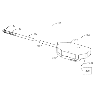
flange (136). Ribbed body portions (132, 134) and narrowed section (164) are
all
sufficiently flexible to accommodate the above-described articulation of end
effector
(150).
1000741 C. Exemplary Robotic Arm Interface Assembly
1000751 FIGS. 5 and 14-18 show interface assembly (200) of the present
example in
greater detail. As shown, interface assembly (200) comprises a base (202) and
a housing
(204). It should be noted that housing (204) is only shown in FIG. 4 and is
omitted from
FIGS. 5 and 14-18 for the sake of clarity. Housing (204) comprises a shell
that simply
encloses drive components. In some versions, housing (204) also includes an
electronic
circuit board, chip, and/or other feature that is configured to identify
instrument (100).
1000761 Base (202) is configured to engage dock (72) of robotic arm cart
(40). While not
shown, it should be understood that base (202) may also include one or more
electrical
contacts and/or other features operable to establish electrical communication
with a
complementary feature of dock (72). A shaft support structure (206) extends
upwardly
from base (202) and provides support to shaft assembly (110) (while still
allowing shaft
assembly (110) to rotate). By way of example only, shaft support structure
(206) may
include a busing, bearings, and/or other features that facilitate rotation of
shaft assembly
(110) relative to support structure (206). As shown in FIG. 5, base (202)
further includes
three drive discs (220, 240, 260) that are rotatable relative to base (202).
Each disc (220,
240, 260) includes a respective pair of unitary pins (222, 242, 262) that
couple with
complementary recesses (not shown) in drive elements of dock (72). In some
versions,
one pin (222, 242, 262) of each pair is closer to the axis of rotation of the
corresponding
disc (220, 240, 260), to ensure proper angular orientation of disc (220, 240,
260) relative
to the corresponding drive element of dock (72).
Date Recue/Date Received 2021-02-19
-21 -
[00077] As best seen in FIGS. 14-16, a drive shaft (224, 244, 264) extends
unitarily
upwardly from each disc (220, 240, 260). As will be described in greater
detail below,
discs (220, 240, 260) are independently operable to provide independent
rotation of shaft
assembly (110), bending of articulation section (130), and translation of
closure tube
(176), through independent rotation of drive shafts (224, 244, 264). Base
(202) also
includes an idle disc (280), which simply does not rotate or drive any
components. A
pair of fixed pivot pins (282, 284) extend unitarily upwardly from disc (280).
1000781 As best seen in FIGS. 14-16, a first helical gear (226) is fixedly
secured to drive
shaft (224), such that rotation of the corresponding disc (220) provides
rotation of first
helical gear (226). First helical gear (226) meshes with a second helical gear
(230),
which is unitarily secured to a sleeve (232). Sleeve (232) is unitarily
secured to outer
sheath (112). Thus, rotation of first helical gear (226) provides rotation of
shaft assembly
(110). It should be understood that rotation of first helical gear (226) about
a first axis is
converted into rotation of second helical gear (230) about a second axis,
which is
orthogonal to the first axis. A clockwise (CW) rotation of second helical gear
(230)
(viewed from the top down) results in CW rotation of shaft assembly (110)
(viewed from
the distal end of shaft assembly (110) toward the proximal end of shaft
assembly (110)),
depending on the thread orientation of helical gears (226, 230). A counter-
clockwise
(CCW) rotation of second helical gear (132) (viewed from the top down) results
in CCW
rotation of shaft assembly (110) (viewed from the distal end of shaft assembly
(110)
toward the proximal end of shaft assembly (110)), again depending on the
thread
orientation of helical gears (226, 230). It should therefore be understood
that shaft
assembly (110) may be actuated by rotating drive shaft (224). Other suitable
ways in
which shaft assembly (110) may be rotated will be apparent to those of
ordinary skill in
the art in view of the teachings herein.
1000791 As also best seen in FIGS. 14-16, a pair of cylindraceous cams
(246, 248) are
fixedly secured to drive shaft (244), such that rotation of the corresponding
disc (240)
provides rotation of cams (246, 248). Cams (246, 248) are both mounted
eccentrically to
drive shaft (244), such that the longitudinal axes of cams (246, 248) are
offset from yet
parallel to the longitudinal axis of drive shaft (244). In addition, cams
(246, 248) are
Date Recue/Date Received 2021-02-19
- 22 -
offset in an opposing manner, such that cams (246, 248) laterally protrude
relative to
drive shaft (244) in opposite directions. Cams (246, 248) are positioned to
drive pivot
arms (286, 288). Pivot arm (286) is pivotally coupled with pivot pin (282),
while pivot
arm (288) is pivotally coupled with pivot pin (284). First drive ring (250)
passes through
an opening (287) formed through first drive arm (286); while second drive ring
(251)
passes through an opening (289) formed through second drive arm (288). Flanges
(252,
253) each have an outer diameter that is larger than the inner diameter of the
corresponding opening (287, 289) Flanges (252, 253) thus restrict distal
movement of
rings (250, 251) relative to respective drive arms (286, 288).
[00080]
As drive shaft (244) is rotated, one of cams (246, 248) will push proximally
on
the corresponding arm (286, 288), depending on the positioning of these
components and
the angular position of cams (246, 248) at the time of rotation. In some
instances, cam
(246) will drive arm (288) proximally, such that arm (288) pivots CCW (viewed
from the
top down) about pin (284). Ann (288) will bear against flange (253) during
such
pivoting, thereby pulling ring (251) and articulation band (142) proximally.
This
proximal movement of articulation band (142) will cause articulation section
(130) to
bend, with end effector (150) being deflected toward band (142). This bending
of
articulation section (130) will pull articulation band (140) distally, which
will in turn pull
ring (250) and its flange (252) distally. The distal motion of flange (252)
will drive arm
(286) distally, such that arm (286) pivots CW (viewed from the top down) about
pin
(282). Cam (248) will be oriented to permit such distal pivoting of arm (286).
As drive
shaft (244) continues to rotate (or if drive shaft (244) is rotated in the
opposite direction),
the above pushing and pulling will eventually be reversed. In other words, cam
(248)
may drive arm (286) proximally while cam (246) permits arm (288) to pivot
distally
during bending of articulation section (130) to provide deflection of end
effector (150)
toward band (140). It should therefore be understood that articulation section
(130) may
be actuated by rotating drive shaft (244). Other suitable ways in which
articulation
section (130) may be actuated will be apparent to those of ordinary skill in
the art in view
of the teachings herein.
Date Recue/Date Received 2021-02-19
- 23 -
[00081] As also best seen in FIGS. 14-16, a cylindraceous cam (266) is
fixedly secured to
drive shaft (264), such that rotation of the corresponding disc (260) provides
rotation of
cam (266). Cam (266) is mounted eccentrically to drive shaft (264), such that
the
longitudinal axis of cam (266) is offset from yet parallel to the longitudinal
axis of drive
shaft (264). Cam (266) is disposed in an oblong opening (272) formed through a
rack
(270), which is translatable relative to base (202). Rack (270) includes a
laterally
extending fork (274). Fork (274) is disposed in an annular recess (278) of
driving ring
(178), which is secured to closure tube (176) as noted above. The
configuration of cam
(266) and the configuration of recess (272) provide a relationship whereby
rack (270)
translates longitudinally in response to rotation of drive shaft (264) and cam
(266). This
translation of rack (270) provides translation of closure tube (176) due to
the engagement
between fork (274) and driving ring (178); and the engagement between driving
ring
(178) and closure tube (176). It should therefore be understood that clamp arm
(152)
may be selectively driven away from or toward blade (160) by rotating drive
shaft (264).
Other suitable ways in which clamp arm (152) may be actuated will be apparent
to those
of ordinary skill in the art in view of the teachings herein.
1000821 D. Exemplary Operation
1000831 In an exemplary use, arm cart (40) is used to insert end effector
(150) into a
patient via a trocar. Articulation section (130) is substantially straight,
and clamp arm
(152) is pivoted toward blade (160), when end effector (150) and part of shaft
assembly
(110) are inserted through the trocar. Drive shaft (224) may be rotated
through drive
features in dock (72) that are coupled with the corresponding disc (220), to
position end
effector (150) at a desired angular orientation relative to the tissue. Drive
shaft (244)
may then be rotated through drive features in dock (72) that are coupled with
the
corresponding disc (240), to pivot or flex articulation section (130) of shaft
assembly
(110) in order to position end effector (150) at a desired position and
orientation relative
to an anatomical structure within the patient. Drive shaft (264) may then be
rotated
through drive features in dock (72) that are coupled with the corresponding
disc (260), to
pivot clamp arm (152) away from blade (160), thereby effectively opening end
effector
(150).
Date Recue/Date Received 2021-02-19
- 24 -
[00084] Tissue of the anatomical structure is then captured between clamp
pad (154) and
blade (160) by rotating drive shaft (264) to advance closure tube (176)
distally, by
actuating drive features in dock (72) that are coupled with the corresponding
disc (260).
In some instances, this involves clamping two layers of tissue forming part of
a natural
lumen defining anatomical structure (e.g., blood vessel, portion of
gastrointestinal tract,
portion of reproductive system, etc.) in a patient; though it should be
understood that
instrument (100) may be used on various kinds of tissues and anatomical
locations. With
tissue captured between clamp pad (154) and blade (160), transducer (120) is
activated to
provide ultrasonic vibrations at blade (160). This simultaneously severs the
tissue and
denatures proteins in adjacent tissue cells, thereby providing a coagulative
effect with
relatively little thermal spread.
1000851 The above operation of shaft assembly (110), articulation section
(130), and end
effector (150) may be repeated as many times as desired in various locations
within the
patient. When the operator wishes to withdraw end effector (150) from the
patient, drive
shaft (244) may be rotated through drive features in dock (72) that are
coupled with the
corresponding disc (240), to straighten articulation section (130). Drive
shaft (264) may
be rotated through drive features in dock (72) that are coupled with the
corresponding
disc (260), to pivot clamp arm (152) toward blade (160), thereby effectively
closing end
effector (150). Arm cart (40) is then used to withdraw end effector (150) from
the patient
and trocar. Other suitable ways in which instrument (100) may be operable and
operated
will be apparent to those of ordinary skill in the art in view of the
teachings herein.
[00086] III. Miscellaneous
1000871 It should be understood that any of the versions of instruments
described herein
may include various other features in addition to or in lieu of those
described above. By
way of example only, any of the instruments described herein may also include
one or
more of the various features disclosed in any of the various references.
[00088] While the examples herein are described mainly in the context of
electrosurgical
instruments, it should be understood that various teachings herein may be
readily applied
to a variety of other types of devices. By way of example only, the various
teachings
Date Recue/Date Received 2021-02-19
- 25 -
herein may be readily applied to other types of electrosurgical instruments,
tissue
graspers, tissue retrieval pouch deploying instruments, surgical staplers,
surgical clip
appliers, ultrasonic surgical instruments, etc.
1000891
In versions where the teachings herein are applied to an electrosurgical
instrument, it should be understood that the teachings herein may be readily
applied to an
ENSEAL Tissue Sealing Device by Ethicon Endo-Surgery, Inc., of Cincinnati,
Ohio.
In addition or in the alternative, it should be understood that the teachings
herein may be
readily combined with the teachings of one or more of the following: U.S. Pat.
No.
6,500,176 entitled "Electrosurgical Systems and Techniques for Sealing
Tissue," issued
December 31, 2002; U.S. Pat. No. 7,112,201 entitled "Electrosurgical
Instrument and
Method of Use," issued September 26, 2006; U.S. Pat. No. 7,125,409, entitled
"Electrosurgical Working End for Controlled Energy Delivery," issued October
24, 2006;
U.S. Pat. No. 7,169,146 entitled "Electrosurgical Probe and Method of Use,"
issued
January 30, 2007; U.S. Pat. No. 7,186,253, entitled "Electrosurgical Jaw
Structure for
Controlled Energy Delivery," issued March 6, 2007; U.S. Pat. No. 7,189,233,
entitled
"Electrosurgical Instrument," issued March 13, 2007; U.S. Pat. No. 7,220,951,
entitled
"Surgical Sealing Surfaces and Methods of Use," issued May 22, 2007; U.S. Pat.
No.
7,309,849, entitled "Polymer Compositions Exhibiting a PTC Property and
Methods of
Fabrication," issued December 18, 2007; U.S. Pat. No. 7,311,709, entitled
"Electrosurgical Instrument and Method of Use," issued December 25, 2007; U.S.
Pat.
No. 7,354,440, entitled "Electrosurgical Instrument and Method of Use," issued
April 8,
2008; U.S. Pat. No. 7,381,209, entitled "Electrosurgical Instrument," issued
June 3, 2008;
U.S. Pub. No. 2011/0087218, entitled "Surgical Instrument Comprising First and
Second
Drive Systems Actuatable by a Common Trigger Mechanism," published April 14,
2011;
U.S. Pub. No. 2012/0116379, entitled "Motor Driven Electrosurgical Device with
Mechanical and Electrical Feedback," published May 10, 2012; U.S. Pub. No.
2012/0078243, entitled "Control Features for Articulating Surgical Device,"
published
March 29, 2012; U.S. Pub. No. 2012/0078247, entitled "Articulation Joint
Features for
Articulating Surgical Device," published March 29, 2012; U.S. Pub. No.
2013/0030428,
entitled "Surgical Instrument with Multi-Phase Trigger Bias," published
January 31,
2013; and/or U.S. Pub. No. 2013/0023868, entitled "Surgical Instrument with
Contained
Date Recue/Date Received 2021-02-19
- 26 -
Dual Helix Actuator Assembly," published January 31, 2013. Other suitable ways
in
which the teachings herein may be applied to an electrosurgical instrument
will be
apparent to those of ordinary skill in the art in view of the teachings
herein.
1000901 In versions where the teachings herein are applied to a surgical
stapling
instrument, it should be understood that the teachings herein may be combined
with the
teachings of one or more of the following: U.S. Pat. No. 7,380,696; U.S. Pat.
No.
7,404,508; U.S. Pat. No. 7,455,208; U.S. Pat. No. 7,506,790; U.S. Pat. No.
7,549,564;
U.S. Pat. No. 7,559,450; U.S. Pat. No. 7,654,431; U.S. Pat. No. 7,780,054;
U.S. Pat. No.
7,784,662; and/or U.S. Pat. No. 7,798,386. Other suitable ways in which the
teachings
herein may be applied to a surgical stapling instrument will be apparent to
those of
ordinary skill in the art in view of the teachings herein.
[00091] Versions described above may be designed to be disposed of after a
single use, or
they can be designed to be used multiple times. Versions may, in either or
both cases, be
reconditioned for reuse after at least one use. Reconditioning may include any
combination of the steps of disassembly of the device, followed by cleaning or
replacement of particular pieces, and subsequent reassembly. In particular,
some
versions of the device may be disassembled, and any number of the particular
pieces or
parts of the device may be selectively replaced or removed in any combination.
Upon
cleaning and/or replacement of particular parts, some versions of the device
may be
reassembled for subsequent use either at a reconditioning facility, or by a
user
immediately prior to a procedure. Those skilled in the art will appreciate
that
reconditioning of a device may utilize a variety of techniques for
disassembly,
cleaning/replacement, and reassembly. Use of such techniques, and the
resulting
reconditioned device, are all within the scope of the present application.
1000921 By way of example only, versions described herein may be sterilized
before
and/or after a procedure. In one sterilization technique, the device is placed
in a closed
and sealed container, such as a plastic or TYVEK bag. The container and device
may
then be placed in a field of radiation that can penetrate the container, such
as gamma
radiation, x-rays, or high-energy electrons. The radiation may kill bacteria
on the device
and in the container. The sterilized device may then be stored in the sterile
container for
Date Recue/Date Received 2021-02-19
- 27 -
later use. A device may also be sterilized using any other technique known in
the art,
including but not limited to beta or gamma radiation, ethylene oxide, or
steam.
[00093]
Having shown and described various embodiments of the present invention,
further adaptations of the methods and systems described herein may be
accomplished by
appropriate modifications by one of ordinary skill in the art without
departing from the
scope of the present invention. Several of such potential modifications have
been
mentioned, and others will be apparent to those skilled in the art. For
instance, the
examples, embodiments, geometrics, materials, dimensions, ratios, steps, and
the like
discussed above are illustrative and are not required. Accordingly, the scope
of the
present invention should be considered in terms of the following claims and is
understood
not to be limited to the details of structure and operation shown and
described in the
specification and drawings.
Date Recue/Date Received 2021-02-19