Note: Descriptions are shown in the official language in which they were submitted.
CA 02904707 2015-09-16
Multi-Range Optical Sensing
BACKGROUND OF THE INVENTION
Field of the Invention
[0001] This invention relates to invasive medical devices. More
particularly, this invention relates to ablation of tissue using such de-
vices.
Description of the Related Art
[0002] Ablation of body tissue using electrical energy is known in
the art. The ablation is typically performed by applying alternating cur-
rents, for example radiofrequency energy, to the electrodes, at a suffi-
cient power to destroy target tissue. Typically, the electrodes are
mounted on the distal tip of a catheter, which is inserted into a subject.
The distal tip may be tracked in a number of different ways known in
the art, for example by measuring magnetic fields generated at the dis-
tal tip by coils external to the subject.
[0003] A known difficulty in the use of radiofrequency energy for
cardiac tissue ablation is controlling local heating of tissue. There are
tradeoffs between the desire to create a sufficiently large lesion to ef-
fectively ablate an abnormal tissue focus, or block an aberrant conduc-
tion pattern, and the undesirable effects of excessive local heating. If
the radiofrequency device creates too small a lesion, then the medical
procedure could be less effective, or could require too much time. On
the other hand, if tissues are heated excessively then there could be lo-
cal charring effects, coagulum, and or explosive steam pops due to
overheating. Such overheated areas can develop high impedance, and
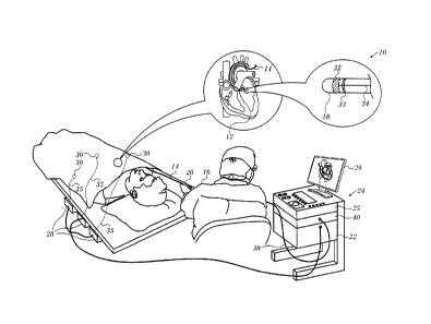
may form a functional barrier to the passage of heat. The use of slower
heating provides better control of the ablation, but unduly prolongs the
procedure.
[0004] U.S. Patent No. 8,147,484 to Lieber et al. discloses real-
time optical measurements of tissue reflection spectral characteristics
1 of 19
CA 02904707 2015-09-16
while performing ablation. The technique involves the radiation of tis-
sue and recapturing of light from the tissue to monitor changes in the
reflected optical intensity as an indicator of steam formation in the tis-
sue for prevention of steam pop. Observation is made to determine
whether measured reflectance spectral intensity (MRSI) increases during
a specified time period followed by a decrease at a specified rate in the
MRSI. If there is a decrease in the MRSI within a specified time and at a
specified rate, then formation of a steam pocket is inferred.
SUMMARY OF THE INVENTION
[0005] Commonly assigned U.S. Provisional Application
No. 61/984953, which is herein incorporated by reference, discloses
that optical reflectivity measured by optical sensors near the tip of a
catheter indicate events, such as imminent occurrence of steam pops.
[0006] According to disclosed embodiments of the invention, the
depth of an ablation lesion is assessed using a differential optical re-
sponse of a catheter with multiple fiberoptic transmitters and receivers
at the tip. To detect tissue optical response at shallow depths, closely-
spaced transmitter/receiver pairs are used. To detect deeper tissue re-
sponse, the same transmitter can be used with another receiver that is
farther away (or vice versa). The distance between the transmitter and
receiver is chosen depending on the desired depth of sensing. Plat-
eauing or peaking of the optical signal during the course of ablation in-
dicates an end point at a selected tissue depth.
[0007] There is provided according to embodiments of the inven-
tion an insertion tube configured for insertion into proximity with tis-
sue in a body of a patient. The tube has an electrical conductor for de-
livering energy to the tissue and a conductive cap attached to the distal
portion of the insertion tube and coupled electrically to the electrical
conductor. A plurality of optical fibers contained within the insertion
tube have terminations at the distal portion. The optical fibers are con-
figurable as optical transmitting fibers to convey optical radiation to the
tissue and as optical receiving fibers to convey reflected optical radia-
2 of 19
CA 02904707 2015-09-16
lion from the tissue. At the distal portion of the insertion tube, the ter-
minations of the optical fibers are spaced apart at respective distances
from one another. An optical module is configured to interrogate the
tissue at a predetermined depth by selectively associating the optical
transmitting fibers with the optical receiving fibers according to the re-
spective distances therebetween, the optical module being operative to
emit light along a light path that passes through a selected optical
transmitting fiber, reflects from the tissue, and returns to the optical
module as reflected light via a selected optical receiving fiber while the
electrical conductor is delivering energy to the tissue. A processor
linked to the optical module analyzes the reflected light.
[0008] According to another aspect of the apparatus, the optical
module is operative for varying an intensity of the light that is emitted
in the light path.
[0009] According to still another aspect of the apparatus, the
emitted light in the light path is monochromatic.
[0010] According to an additional aspect of the apparatus, the
emitted light in the light path has a wavelength of 675 nm.
[0011] According to another aspect of the apparatus, the selec-
tively associated optical transmitting fibers and optical receiving fibers
are spaced apart by intervals of 0.5 - 2 mm.
[0012] According to one aspect of the apparatus, analyzing the
reflected light includes determining a time at which the reflected light
ceases to vary in intensity by more than a predetermined rate.
[0013] According to a further aspect of the apparatus, analyzing
the reflected light includes identifying a time of a peak in intensity in
the returning light.
[0014] According to still another aspect of the apparatus, analyz-
ing the reflected light includes determining at respective depths of in-
terrogation times at which variations in a rate of change of a reflected
light intensity by more than a predetermined percentage occur.
3 of 19
CA 02904707 2015-09-16
[0015] According to an additional aspect of the apparatus, ana-
lyzing the reflected light includes calculating a ratio of two wavelengths
and determining a time at which the ratio ceases to vary by more than a
predetermined rate.
[0016] There is further provided according to embodiments of
the invention a method, which is carried out by configuring optical fi-
bers contained within a probe as optical transmitting fibers and as opti-
cal receiving fibers, wherein terminations of the optical fibers are
spaced apart at respective distances from one another, inserting the
probe into a body of a patient. While delivering energy to a tissue in the
body through an ablator of the probe, the method is further carried out
by interrogating the tissue at a predetermined depth by selectively as-
sociating one of the optical transmitting fibers with one of the optical
receiving fibers according to the respective distances therebetween, and
establishing a light path extending from a light emitter through the one
optical transmitting fiber to reflect from the tissue and continuing as
reflected light from the tissue through the one optical receiving fiber to
a receiver. The method is further carried out by transmitting light from
the light emitter along the light path, and analyzing the reflected light
reaching the receiver via the one optical receiving fiber.
BRIEF DESCRIPTION OF THE SEVERAL VIEWS OF THE DRAWINGS
[0017] For a better understanding of the present invention, ref-
erence is made to the detailed description of the invention, by way of
example, which is to be read in conjunction with the following draw-
ings, wherein like elements are given like reference numerals, and
wherein:
[0018]
Fig. 1 is a pictorial illustration of a system for performing
ablative procedures, which is constructed and operative in accordance
with a disclosed embodiment of the invention;
[0019] Fig. 2 is a
schematic, perspective illustration of a catheter
cap in accordance with an embodiment of the invention;
4 of 19
CA 02904707 2015-09-16
[0020]
Fig. 3 is an isometric view of the distal end of a catheter
in accordance with an alternate embodiment of the invention;
[0021]
Fig. 4 is a schematic side view taken along line 5-5 of
Fig. 4, in accordance with an embodiment of the invention;
[0022] Fig. 5
schematically illustrates paths taken by light
to/from windows in the cap shown in Fig. 2, in accordance with an em-
bodiment of the invention;
[0023]
Fig. 6 is a schematic view of the distal end of a catheter,
in accordance with an embodiment of the invention;
[0024] Fig. 7 is a
plot that relates the inter-element distance of an
optical receiver-transmitter pair in a catheter to the elapsed time at
which an ablation endpoint is observed, in accordance with an embodi-
ment of the invention; and
[0025]
Fig. 8 is a series of plots showing the effect of varying the
intensity of optical radiation, in accordance with an embodiment of the
invention.
DETAILED DESCRIPTION OF THE INVENTION
[0026] In
the following description, numerous specific details are
set forth in order to provide a thorough understanding of the various
principles of the present invention. It will be apparent to one skilled in
the art, however, that not all these details are necessarily needed for
practicing the present invention. In this instance, well-known circuits,
control logic, and the details of computer program instructions for
conventional algorithms and processes have not been shown in detail in
order not to obscure the general concepts unnecessarily.
Overview
[0027] Turning now to the drawings, reference is initially made
to Fig. 1, which is a pictorial illustration of a system 10 for evaluating
electrical activity and performing ablative procedures on a heart 12 of a
living subject, which is constructed and operative in accordance with a
disclosed embodiment of the invention. The system comprises a cathe-
5 of 19
CA 02904707 2015-09-16
. .
ter 14, which is percutaneously inserted by an operator 16 through the
patient's vascular system into a chamber or vascular structure of the
heart 12. The operator 16, who is typically a physician, brings the cathe-
ter's distal tip 18 into contact with the heart wall, for example, at an ab-
lation target site. Electrical activation maps may be prepared, according
to the methods disclosed in U.S. Patent Nos. 6,226,542, and 6,301,496,
and in commonly assigned U.S. Patent No. 6,892,091, whose disclosures
are herein incorporated by reference. One commercial product embody-
ing elements of the system 10 is available as the CARTO 3 System,
available from Biosense Webster, Inc., 3333 Diamond Canyon Road, Di-
amond Bar, CA 91765. This system may be modified by those skilled in
the art to embody the principles of the invention described herein.
[0028] Areas determined to be abnormal, for example by evalua-
tion of the electrical activation maps, can be ablated by application of
thermal energy, e.g., by passage of radiofrequency electrical current
through wires in the catheter to one or more electrodes at the distal
tip 18, which apply the radiofrequency energy to the myocardium. The
energy is absorbed in the tissue, heating it to a point (typically
above 50 C) at which it permanently loses its electrical excitability.
When successful, this procedure creates non-conducting lesions in the
cardiac tissue, which disrupt the abnormal electrical pathway causing
the arrhythmia. The principles of the invention can be applied to differ-
ent heart chambers to diagnose and treat many different cardiac ar-
rhythmias.
[0029] The catheter 14 typically comprises a handle 20, having
suitable controls on the handle to enable the operator 16 to steer, posi-
tion and orient the distal end of the catheter as desired for the ablation.
To aid the operator 16, the distal portion of the catheter 14 contains po-
sition sensors (not shown) that provide signals to a processor 22, locat-
ed in a console 24. The processor 22 may fulfill several processing func-
tions as described below.
6 of 19
CA 02904707 2015-09-16
[0030] Ablation energy and electrical signals can be conveyed to
and from the heart 12 through one or more ablation electrodes 32 locat-
ed at or near the distal tip 18 via cable 34 to the console 24. Pacing sig-
nals and other control signals may be conveyed from the console 24
through the cable 34 and the electrodes 32 to the heart 12. Sensing elec-
trodes 33, also connected to the console 24 are disposed between the
ablation electrodes 32 and have connections to the cable 34.
[0031] Wire connections 35 link the console 24 with body surface
electrodes 30 and other components of a positioning sub-system for
measuring location and orientation coordinates of the catheter 14. The
processor 22 or another processor (not shown) may be an element of the
positioning subsystem. The electrodes 32 and the body surface elec-
trodes 30 may be used to measure tissue impedance at the ablation site
as taught in U.S. Patent No. 7,536,218, issued to Govari et al., which is
herein incorporated by reference. A temperature sensor (not shown),
typically a thermocouple or thermistor, may be mounted on or near
each of the electrodes 32.
[0032] The console 24 typically contains one or more ablation
power generators 25. The catheter 14 may be adapted to conduct abla-
tive energy to the heart using any known ablation technique, e.g., ra-
diofrequency energy, ultrasound energy, and laser-produced light ener-
gy. Such methods are disclosed in commonly assigned U.S. Patent
Nos. 6,814,733, 6,997,924, and 7,156,816, which are
here-
in incorporated by reference.
[0033] In one embodiment, the positioning subsystem comprises
a magnetic position tracking arrangement that determines the position
and orientation of the catheter 14 by generating magnetic fields in a
predefined working volume and sensing these fields at the catheter, us-
ing field generating coils 28. The positioning subsystem is described in
U.S. Patent No. 7,756,576, which is hereby incorporated by reference,
and in the above-noted U.S. Patent No. 7,536,218.
7 of 19
CA 02904707 2015-09-16
[0034] As noted above, the catheter 14 is coupled to the con-
sole 24, which enables the operator 16 to observe and regulate the func-
tions of the catheter 14. Console 24 includes a processor, preferably a
computer with appropriate signal processing circuits. The processor is
coupled to drive a monitor 29. The signal processing circuits typically
receive, amplify, filter and digitize signals from the catheter 14, includ-
ing signals generated by sensors such as electrical, temperature and
contact force sensors, and a plurality of location sensing electrodes (not
shown) located distally in the catheter 14. The digitized signals are re-
ceived and used by the console 24 and the positioning system to com-
pute the position and orientation of the catheter 14, and to analyze the
electrical signals from the electrodes.
[0035] In
order to generate electroanatomic maps, the proces-
sor 22 typically comprises an electroanatomic map generator, an image
registration program, an image or data analysis program and a graphical
user interface configured to present graphical information on the moni-
tor 29.
[0036] An optical module 40 provides optical radiation, typically
from, but not limited to, a laser, an incandescent lamp, an arc lamp, or a
light emitting diode (LED), for transmission from distal tip 18 to the tar-
get tissue. The module receives and cooperatively with the processor 22
analyzes optical radiation returning from the target tissue and acquired
at the distal end, as described below.
[0037] Typically, the system 10 includes other elements, which
are not shown in the figures for the sake of simplicity. For example, the
system 10 may include an electrocardiogram (ECG) monitor, coupled to
receive signals from one or more body surface electrodes, in order to
provide an ECG synchronization signal to the console 24. As mentioned
above, the system 10 typically also includes a reference position sensor,
either on an externally-applied reference patch attached to the exterior
of the subject's body, or on an internally-placed catheter, which is in-
serted into the heart 12 maintained in a fixed position relative to the
8 of 19
CA 02904707 2015-09-16
heart 12. Conventional pumps and lines for circulating liquids through
the catheter 14 for cooling the ablation site are provided. The system 10
may receive image data from an external imaging modality, such as an
MRI unit or the like and includes image processors that can be incorpo-
rated in or invoked by the processor 22 for generating and displaying
images.
[0038] Reference is now made to Fig. 2, which is a schematic,
perspective illustration of a catheter cap 100, in accordance with an
embodiment of the invention. Cap 100 comprises a side wall 74 that is
on the order of 0.4 mm thick, in order to provide the desired thermal
insulation between optional temperature sensors 48 and the irrigation
fluid inside a central cavity 76 of the tip. Irrigation fluid exits cavity 76
through apertures 46.
[0039] Reference is now made to Fig. 3, which is an isometric
view of the distal end of a cap 113 for a catheter in accordance with an
alternate embodiment of the invention. In this embodiment six open-
ings 114 are located at distal end 115. As explained below the open-
ing 114 constitute windows at the terminations of fiberoptic elements
that extend longitudinally through the catheter 14 into the cap 113. In
other embodiments, the cap 113 may be provided with other windows
(not shown) to accommodate sensors, e.g., temperature or contact force
sensors.
[0040] Reference is now made to Fig. 4, which is a schematic side
view showing the interior of the cap 100 (Fig. 2), in accordance with an
embodiment of the invention. Three through longitudinal bores 102 and
three blind longitudinal bores 72 are formed in side wall 74. The three
sets of bores 72, 102 may be distributed symmetrically around a longi-
tudinal axis of cap 100. However, the bores are not necessarily distrib-
uted symmetrically around the axis. Optional sensors 48 are mounted in
hollow tubes 78, which are filled with a suitable glue, such as epoxy and
fitted into longitudinal bores 72 in side wall 74. Tubes 78 may comprise
a suitable plastic material, such as polyimide, and may be held in place
9 of 19
CA 02904707 2015-09-16
. .
by a suitable glue, such as epoxy. This arrangement provides an array of
sensors 48, with possible advantages of greater ease of manufacture and
durability.
[0041] Each through longitudinal bore 102 terminates in an open-
ing 114 in the surface of wall 74, and a transparent window 116 is
placed in the opening. A fiber optic 118 is inserted into each of the
through bores. In some embodiments, temperature sensors 48 may not
be installed, and only fiber optics 118 are incorporated into the wall.
Such an embodiment enables determination of tissue contact with the
cap, and/or characterization of the tissue in proximity to the cap, by
methods described below.
[0042] Window 116 acts as a seal preventing fluid external to the
outer surface of cap 100 from penetrating into the bores containing the
fiber optics. Window 116 may be formed by filling opening 114 with an
optically transparent glue or epoxy. In some embodiments, the material
of the windows may be filled with a scattering agent to diffuse light
passing through the windows.
[0043] Alternatively, the windows may be formed from an optical
quality flat or lensed material, and may be secured to their openings
with glue.
[0044] In one embodiment, each fiber optic 118 or each fiber op-
tic 128 is a single fiber optic, typically having a diameter of approxi-
mately 175 pm. In an alternative embodiment each fiber optic 118 or
each fiber optic 128 comprises a bundle of substantially similar fiber
optics, typically having a bundle diameter also of approximately 175
pm. Implementing the fiber optics as bundles increases the flexibility of
cap 100 with respect to more proximal regions of the catheter 14
(Fig. 1).
[0045] Such an increase in flexibility is advantageous if cap
100
is connected to the more proximal regions of the catheter by a spring
whose deflections are measured for the purpose of measuring a force on
the cap, since the increased flexibility means there is little or no change
10 of 19
CA 02904707 2015-09-16
in the spring deflection for a given force. A spring that may be used to
join the cap 100 to the more proximal regions of the catheter is de-
scribed in U.S. Patent Application Publication No. 2011/0130648 by
Beeckler et al., whose disclosure is incorporated herein by reference.
[0046] Optical module 40 (Fig. 1) is configured to be able to pro-
vide optical radiation to any one of fiber optics 118 and 128, for trans-
mission from any of the associated windows 116, 124 in order to irradi-
ate tissue in proximity to cap 100. Simultaneously, the optical mod-
ule 40 is able to acquire, via any or all of the windows, radiation return-
ing from the irradiated tissue.
[0047] The array of windows 116, 124, and their associated fiber
optics, enables embodiments of the present invention to employ a num-
ber of different methods, using optical radiation, for determining char-
acteristics of the irradiated tissue, as well as the proximity of cap 100,
or a region of the cap, with respect to the tissue. By way of example,
three such methods are described below, but those having ordinary skill
in the art will be aware of other methods, and all such methods are in-
cluded within the scope of the present invention.
[0048] A first method detects contact of any one of windows 116,
124, and consequently of the catheter, with tissue. Optical radiation, of
a known intensity, is transmitted through each fiber optic, to exit from
the optic's window. The intensity of the radiation returning to the win-
dow is measured while cap 100 is not in contact with tissue, typically
while the cap is in the blood of heart 12 (Fig. 1). Optical module 40 may
use these intensities as reference values of the optical radiation.
[0049] For any given window, a change in the value from the
window's reference value, as measured by the module, may be taken to
indicate that the window is in contact with tissue.
[0050] A second method measures characteristics of tissue being
irradiated by the optical radiation. Reference is now made to Fig. 6,
which schematically illustrates paths taken by light to/from windows in
the cap 100 (Fig. 2), in accordance with an embodiment of the invention.
11 of 19
CA 02904707 2015-09-16
. .
[0051]
As illustrated in Fig. 5, for all six windows 116, 124 there
are a total of 21 different paths, comprising 6 paths 150 where radiation
from a given window returns to that window, and 15 paths 160 where
radiation from a given window returns to a different window. The
change of optical radiation for a given path or group of paths depends
on characteristics of tissue in the path or group of paths, so that meas-
urements of the change in all of the paths provide information related
to characteristics of the tissue in proximity to cap 100.
[0052] For example, the change in all of the paths may be meas-
ured by sequentially transmitting, in a time multiplexed manner, optical
radiation from each of the windows 116, 124, and measuring the return-
ing radiation. A first transmission from a first window in such a se-
quence provides values for five paths 160 plus a return path 150 to the
first window. A second transmission from a second window provides
values for four new paths 160 plus return path 150 to the second win-
dow. A third transmission from a third window provides values for
three new paths 160 plus return path 150 to the third window. A fourth
transmission from a fourth window provides values for two new paths
160 plus return path 150 to the fourth window. A fifth transmission
from a fifth window provides values for one new path 160 to the sixth
window, and return path 150 to the fifth window). A sixth and final
transmission from a sixth window provides one return path 150 through
the sixth window.
[0053]
Optical module 40 (Fig. 1) enables a first portion of the fi-
bers as optical transmitting fibers and a second portion of the fibers as
optical receiving fibers. The optical module 40 selectively associates the
optical transmitting fibers with the optical receiving fibers to produce a
light path passing through a selected optical transmitting fiber, reflect-
ing from the target tissue, and returning via a selected optical receiving
fiber. As the first portion and the second portion of the fibers are
spaced apart at respective distances, by appropriate choice of an optical
transmitting fiber and an optical receiving fiber, the optical module 40
12 of 19
CA 02904707 2015-09-16
is able to interrogate the target tissue at a desired depth according to
inter-element spacing between the optical transmitting fiber and the op-
tical receiving fiber. The optical module 40 cooperatively with the pro-
cessor 22 (Fig. 1) may measure the changes of all the paths, and, using a
calibration procedure, may derive from the changes optical characteris-
tics of tissue within the paths. Such characteristics may include an
overall level of ablation of tissue, or an amount and/or type of necrotic
tissue, in the paths.
[0054] The light in the light path may be monochromatic light,
for example at a wavelength of 675 nm. Alternatively, the light may
have broader spectrum.
[0055] Reference is now made to Fig. 6, which is a schematic
view of the distal end of a catheter, in accordance with an embodiment
of the invention. Nine terminations of fiberoptic elements (0, A - H) are
shown. Chords 0A-OH connect element 0 with elements A-H, respective-
ly. The accompanying table indicates the corresponding inter-element
distances of the terminations. While Fig. 7 exhaustively depicts light
paths in respect of element 0, in practice not all of the positions need
be dedicated to fiberoptic elements. In a current embodiment, three p0-
sitions (elements H, B, and E) are assigned to temperature sensors,
thereby leaving fewer light paths to be selected,
Operation
[0056]
Continuing to refer to Fig. 6, the catheter is operated in
cooperation with the system 10 (Fig. 1) by configuring an element, e.g.,
element 0, as one member of an optical receiver-transmitter pair and
another element, e.g., elements A-H as the other member. The selected
receiver-transmitter pair is optimum for interrogating the ablation site
at a respective depth. For example, an inter-element distance of 0.5 mm
is optimum for a shallow depth of interrogation. An inter-element dis-
tance of about 2 mm is optimum for a deeper level of approximately 2-
3mm. The selected inter-element distance may be varied, either by hold-
ing one element, e.g., element 0, fixed, and analyzing the other ele-
13 of 19
CA 02904707 2015-09-16
ments in turn, or by changing the pairing according to a predetermined
schedule. In any case, the reflectances measured by the pairs are ana-
lyzed as the ablation proceeds. Once the signal is received using the
largest inter-element distance stabilizes (or peaks), it may be concluded
that no further changes are occurring in the tissue at that level. Alt-
hough the optical interrogation depth is approximately 2-3 mm, the to-
tal depth of the lesion can be extrapolated based upon the magnitude of
change at the maximum interrogation depth. Alternatively, by operating
a plurality of the elements as optical transmitters at respective wave-
lengths, multiple receiver-transmitter pairs may be operated concurrent-
ly.
Results
[0057] Reference is now made to Fig. 7, which is a plot that re-
lates the inter-element distance of optical receiver-transmitter pairs in a
catheter to the elapsed time at which a change in optical intensity is ob-
served, in accordance with an embodiment of the invention. In a medi-
cal procedure of this sort, the depth of ablation increases with elapsed
time. A correlation is shown between the interrogation depth at a par-
ticular distance and the elapsed time, indicating that optical
reflectances at increasing receiver-transmitter pair distances are useful
for detecting increasing ablation depths.
[0058] Reference is now made to Fig. 8, which is a series of plots
showing the effect of varying the intensity of optical radiation, in ac-
cordance with an embodiment of the invention. An endpoint may be de-
termined by establishing a time at which the intensity of the reflected
light fails to vary by more than a predetermined rate. Alternatively, the
endpoint may be determined by identification of a peak in the intensity
of the reflected light endpoints 162, 162, 164, 166.
[0059] Alternatively, the endpoint may be determined by trans-
mitting light through a path via the fiberoptic elements at two wave-
lengths and calculating a ratio of the reflected light at the two wave-
14 of 19
CA 02904707 2015-09-16
lengths. The endpoint may be defined as a time at which the ratio ceas-
es to vary by more than a predetermined rate.
[0060] Analysis of reflectance data may comprise identification
of a point (referred to herein as a "startpoint"). As the interrogation
depth increases, startpoints represents times at which variations in the
rate of change of reflectance by more than a predetermined percentage
occur. Such startpoints correspond respectively to different interroga-
tion depths. The first startpoints occur at shallow interrogation depths
and the later instances occur at deeper interrogation depths.
[0061] The lowermost plot was obtained using the highest sepa-
ration distance, and exhibits a distinct peak, whereas lower separation
distances result in a flattening or plateau after an endpoint of the abla-
tion is reached as shown by points 162, 164, 166, 168.
[0062] It
will be appreciated by persons skilled in the art that the
present invention is not limited to what has been particularly shown
and described hereinabove. Rather, the scope of the present invention
includes both combinations and sub-combinations of the various
features described hereinabove, as well as variations and modifications
thereof that are not in the prior art, which would occur to persons
skilled in the art upon reading the foregoing description.
15 of 19