Note: Descriptions are shown in the official language in which they were submitted.
CA 02905178 2015-09-09
WO 2014/145619
PCT/US2014/030414
DEVICE AND ASSOCIATED METHODS FOR PERFORMING LUMINESCENCE
AND FLUORESCENCE MEASUREMENTS OF A SAMPLE
CROSS-REFERENCE TO RELATED APPLICATIONS
[0001] This application is related to and claims priority to U.S. Provisional
Patent
Application Serial Nos. 61/791,295 and 61/791,879, each of which were filed on
March 15, 2013, the complete and entire disclosures of which are hereby
expressly
incorporated by reference herein.
TECHNICAL FIELD
[0002] The present teachings are related to a system and process for
performing
diagnostic assays, and more particularly to an automated immunoanalyzer system
and
process for performing diagnostic assays for allergies and autoimmune
diseases.
BACKGROUND OF THE DISCLOSURE
[0002] The statements in this section merely provide background information
related to
the present disclosure and should not be construed as constituting prior art.
[0003] During an automated immunochemistry analysis, analyte molecules in a
patient's
biological sample (e.g. serum or plasma) attach to paramagnetic particles. To
remove
background signals associated with potential chemical sources that may be
present in the
sample as well, a number of washing steps are typically implemented into the
process. A
consequence of these washing steps, however, is that some fraction of the
original particles
will be lost for subsequent chemistry processes.
[0004] As such, there is a need for a process that allows the particles
remaining after the
washing steps to be quantified in order to normalize the luminescence signal
from the
patient sample. The present application is intended to improve upon and
resolve some of
these known deficiencies of the art.
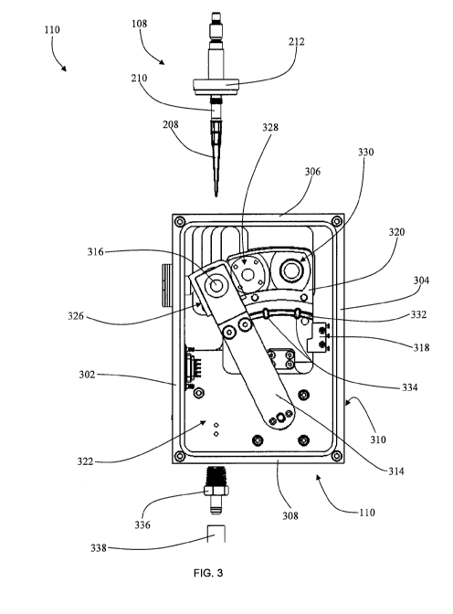
1
CA 02905178 2015-09-09
WO 2014/145619
PCT/US2014/030414
SUMMARY OF THE DISCLOSURE
[0005] In accordance with one aspect of the present application, a process for
optically
measuring a dynamic chemical range of a sample in a reaction cuvette is
provided. In
accordance with this aspect of the present disclosure, the process comprises
moving an
optical detector from a luminescence reading position within a light tight
optics box to a
fluorescence reading position within the light tight optics box. By moving the
optical
detector to the fluorescence reading position, crosstalk from the fluorescence
light source
can be minimized.
[0006] According to another aspect of the present disclosure, an optical
reading
subassembly for an automated immunochemistry analyzer is provided and
comprises an
optical pipette configured to aspirate a sample from a cuvette as part of a
chemistry process
on an automated analyzer; an opaque optics box, which mates in a light tight
manner with
the optical pipette, with a common end and an emission end of a bifurcated
optical fiber
bundle, with a drain tube, and with a multi-pin electrical power/signal
connector; a
fluorescence excitation light source; a bifurcated fiber optic bundle, one leg
of which is
connected to the light source, one leg of which is connected through a series
of emission
optical filters to a fluorescence detection port of the optics box, and whose
common end is
connected to the optics box so that it can efficiently illuminate and thereby
excite a
fluorescent sample in the tip of the optical pipette and simultaneously
collect a portion of
the emission light from that fluorescent sample; a drain port, which allows
droplets of fluid
from the pipette tip to be removed from the optics box, without introducing
stray light into
the box; an optical detector with enough dynamic range to measure both
fluorescence and
luminescence signal from the samples; and a shutter mechanism, which can move
the
optical detector between a luminescence reading position, a fluorescence
reading position,
and an optically dark position.
[0007] In accordance with another aspect of the present disclosure, an
apparatus for
measuring the luminescence and the fluorescence of a sample is provided and
comprises a
light tight optics box capable of receiving a pipette tip containing a sample;
an optical
sensor located within the optics box and capable of being disposed in both a
luminescence
reading position and a fluorescence reading position; an excitation light
fiber optic bundle
2
CA 02905178 2015-09-09
WO 2014/145619
PCT/US2014/030414
and a sample transmission fiber optic bundle; an excitation light assembly
that projects
excitation light onto a first terminus end of the excitation light fiber optic
bundle; and an
in-line filter located along the sample transmission fiber optic bundle;
wherein the optical
sensor observes a luminescence reading from the sample while in the
luminescence reading
position and then transfers to the fluorescence reading position to project
excitation light
into one end of the excitation light fiber optic bundle, the excitation light
fiber optic bundle
being configured to transfer the excitation light onto the sample in the
pipette tip; and
wherein the transmission fiber optic bundle is configured to transmit the
observed
luminescence reading of the sample through the in-line filter and to the
optical sensor
disposed in the fluorescence reading position.
[0008] In accordance with still another aspect of the present disclosure, an
automated
method for controlling an automated fluorescence and luminescence reading
device is
provided and comprises the steps of moving an optics pipettor from a neutral
position to a
position within a cuvette; aspirating a sample from the cuvette; raising the
optics pipettor
out of the cuvette and positioning the sample at the tip of the optics
pipettor by aspirating a
volume of air; moving the optics pipettor to orient a clear tip of the optics
pipettor within
the internal region of an optics box; rotating an optical sensor from a second
position to a
first position via an electric motor; measuring and recording the luminescence
reading
from the optical sensor; rotating the optical sensor to a third position;
enabling an
excitation light emitting diode to project excitation light onto one terminus
end of an
excitation fiber optic bundle; projecting the excitation light from the
excitation fiber optic
bundle onto the sample; transmitting an observed reaction through a
transmission fiber
optic bundle to a transmission terminus end disposed across from the optical
sensor;
measuring and recording the fluorescence reading projected from the
transmission
terminus end onto the optical sensor; rotating the optical sensor to the
second position;
measuring and recording a dark reading while the optical sensor is in the
second position;
moving the optics pipettor from the optics box to a wash station; flushing the
sample from
the optics pipet-tor by dispensing a volume of air; aspirating a system liquid
into the optics
pipettor and dispersing the system liquid in a wash cycle; and moving the
optics pipettor to
the neutral position in preparation for the next sample.
3
CA 02905178 2015-09-09
WO 2014/145619
PCT/US2014/030414
[0009] In accordance with yet another aspect of the present disclosure, an
automated
fluorescence and luminescence reading machine is provided and comprises an
optics
pipettor that has a clear tip, an opaque body, and a disc feature around the
opaque body; a
pipette transfer arm that transfers the optics pipettor to a plurality of
locations, the plurality
of locations including a read position, a wash position, and a sample
aspiration position; an
optics box that can encompass a light tight internal environment when the
optics pipettor is
in the read position; a drain port coupled to the optics box, the drain port
coupling to a
drain tube that transfers any excess liquid out of the internal environment; a
first fiber optic
transition coupled to the optics box, the first fiber optic transition
creating a light-tight seal
to allow a first fiber optic bundle to expose an emission terminus end inside
the internal
environment; a second fiber optic transition coupled to the optics box, the
second fiber
optic transition creating a light-tight seal to allow a common terminus fiber
optic bundle to
expose a common terminus end inside the internal environment; a stepper motor
coupled to
a shutter mechanism; an optical sensor coupled to the shutter mechanism, the
shutter
mechanism and the stepper motor controlling the orientation of the optical
sensor; an
optical alignment plate containing a first reading position, a second reading
position, and a
third reading position; and a reentrant seal on the optics box, the reentrant
seal designed to
partially mate with the disc feature around the opaque body of the optics
pipettor, a
fluorescence excitation assembly that houses a light emitting diode, the light
emitting
diode configured to transmit a fluorescence signal to a terminus end of a
fluorescence
excitation fiber optic bundle; wherein when the pipette transfer arm transfers
the optics
pipettor to the read position, the reentrant seal and the disc feature may
partially mate to
one another to prevent light from entering the internal environment; and
wherein when the
pipette is in the read position, the optical sensor may be aligned in the
first reading position
where the luminescence reading of a sample within the clear tip may be
measured by the
optical sensor and when the optical sensor is aligned in the third reading
position where a
fluorescence measurement is obtained from the sample in the clear tip through
the
emission terminus end of the first fiber optic bundle.
4
CA 02905178 2015-09-09
WO 2014/145619
PCT/US2014/030414
BRIEF DESCRIPTION OF THE DRAWINGS
[0010] The above-mentioned aspects of the present invention and the manner of
obtaining them will become more apparent and the invention itself will be
better
understood by reference to the following description of the embodiments of the
invention
taken in conjunction with the accompanying drawings, wherein:
[0011] FIG. 1 is a top schematic view of an automated immunochemistry analyzer
and
reagent system in accordance with the teachings of the present application;
[0012] FIG. 2 is a perspective view of the optical subassembly of the
automated
immunochemistry analyzer and reagent system of FIG. 1;
[0013] FIG. 3 is a front side view of a portion of the optical subassembly of
FIG. 2 with
a front surface removed;
[0014] FIG. 4 is an exploded perspective view of some of the internal
components of the
portion of the optical subassembly of FIG. 3;
[0015] FIG. 5 is a partial section view of the portion of the optical
subassembly of FIG. 3
with an optical sensor in a first position and an optical pipettor disposed
therein;
[0016] FIG. 6 is a partial section view of the portion of the optical
subassembly of FIG. 3
with the optical sensor in a third position;
[0017] FIG. 7 is a partial section view of the portion of the optical
subassembly of FIG. 3
with a pipettor disposed within the optical subassembly;
[0018] FIG. 8 is a perspective view of an in-line fiber optic light filter
assembly in
accordance with the teachings of the present application;
[0019] FIG. 9 is an exploded perspective view of the in-line fiber optic light
filter
assembly of FIG. 8.
[0020] FIG. 10 is a perspective view of a fluorescence excitation subassembly
in
accordance with the teachings of the present application;
[0021] FIG. 11 is a section view of the fluorescence excitation subassembly of
FIG. 10;
[0022] FIG. 12 is a top side section view of a bifurcated fiber optic cable
routing system
in accordance with the teachings of the present application; and
[0023] FIG. 13 is a flowchart showing system control logic for the optical
subassembly
of FIG. 2.
CA 02905178 2015-09-09
WO 2014/145619
PCT/US2014/030414
[0024] Corresponding reference characters indicate corresponding parts
throughout the
several views. Although the exemplification set out herein illustrates
embodiments of the
invention, in several forms, the embodiments disclosed below are not intended
to be
exhaustive or to be construed as limiting the scope of the invention to the
precise forms
disclosed.
DETAILED DESCRIPTION
[0025] The above-mentioned aspects of the present application and the manner
of
obtaining them will become more apparent and the teachings of the present
application
itself will be better understood by reference to the following description of
the
embodiments of the present application. Moreover, although the exemplification
set out
herein illustrates embodiments of the present application, in several forms,
the
embodiments disclosed below are not intended to be exhaustive or to be
construed as
limiting the scope of the present application to the precise forms disclosed.
Rather, the
embodiments are chosen and described so that others skilled in the art may
appreciate and
understand the principles and practices of the present application.
[0026] Unless defined otherwise, all technical and scientific terms used
herein have the
same meaning as commonly understood by one of ordinary skill in the art to
which this
application belongs. Although any method and materials similar or equivalent
to those
described herein can be used in the practice or testing of the present
application, the
specific methods and materials are now described.
[0027] FIG. 1 illustrates the various components of an automated diagnostic
immunochemistry analyzer 100 in accordance with the teachings of the present
disclosure.
The automated immunochemistry analyzer 100 can take an analyte sample, create
an
environment that will allow it to bind to a paramagnetic particle, perform a
number of
washing steps, then quantify and normalize the luminescence signal of the
analyte sample.
This can be accomplished through an automated process that utilizes a vortexer
102, an R1
pipettor 104, a reaction rotor 106, an optics pipettor 108, an optics box 110,
a multi rinse
pipettor 112, a reagent rotor 114, a single rinse pipettor 116, a sample rotor
118, a sample
pipettor 120, an R2 pipettor 122, and a mixed substrate container 124.
6
CA 02905178 2015-09-09
WO 2014/145619
PCT/US2014/030414
[0028] To better understand the mechanical aspects of this disclosure, a
sample process
will be outlined explaining one possible method the apparatus could utilize to
quantify and
normalize the luminescence signal of an analyte sample. Specifically, the
automated
immunochemistry analyzer 100 begins by first dispensing fluorescently labelled
paramagnetic particles, or fluo-beads, into a cuvette located within the
reaction rotor 106.
The fluo-beads may initially be located in the vortexer 102 and be transferred
to the
reaction rotor 106 by the R1 pipettor 104. The R1 pipettor 104 can aspirate a
desired
quantity of the fluo-bead mixture and transfer the aspirated quantity to the
reaction rotor
106 where it is injected into the cuvette of the reaction rotor 106. Following
the injection
into the cuvette, the optics pipettor 108 may aspirate a test sample from the
cuvette of the
reaction rotor 106 and transfer the test sample to the optics box 110. Once
the sample is
disposed within the optics box 110, fluorescence and luminescence measurements
can be
recorded. The initial recording of the fluorescence and luminescence signal
can be used as
a baseline measurement for the fluorescence signal that can correspond to the
initial
concentration of fluo-beads in a sample. After recording the measurements, the
multi rinse
pipettor 112 can rinse the cuvettes using a wash buffer.
[0029] Next, fluo-beads may be transferred from the vortexer 102 to a cuvette
in the
reaction rotor 106 via the R1 pipettor 104. Then, the R1 pipettor 104 may
aspirate a
capture reagent from the reagent rotor 114 and inject the capture reagent into
the cuvette
located in the reaction rotor 106. After an incubation period, the single
rinse pipettor 116
may inject a rinse buffer to resuspend the fluo-bead. A substantial amount of
the suspended
fluo-bead may then be localized by magnets within the reaction rotor 106 over
a period of
time. After the magnets have substantially localized the fluo-beads within the
cuvette, the
multi rinse pipettor 112 may aspirate and dispose of a portion of the rinse
buffer, leaving a
portion of the fluo-beads localized within the cuvette. The multi rinse
pipettor 112 may
proceed to inject a wash buffer into the cuvette of the reaction rotor 106,
resuspending the
fluo-beads. The fluo-beads may again be localized by the magnets within the
reaction rotor
106 to be followed by the multi rinse pipettor 112 aspirating and discarding a
portion of
the sample that was not localized from the cuvette in the reaction rotor 106.
7
CA 02905178 2015-09-09
WO 2014/145619
PCT/US2014/030414
[0030] A patient sample may be contained in a sample tube on in the sample
rotor 118.
The patient sample may further be partially diluted with a sample diluent. At
this point, the
sample pipettor 120 may aspirate a portion of the patient sample and inject
the patient
sample into the cuvette of the reaction rotor 106 to resuspend the fluo-beads.
The cuvette
containing the patient sample within the reaction rotor 106 may then incubate
the patient
sample. In one embodiment, the incubation temperature can be about 37 degrees
Celsius
+/- about 0.2 degree Celsius while the incubation time can be about 37.75
minutes +/-
about 2 minutes. After incubation, the single rinse pipettor 116 may inject
the rinse buffer
to again resuspend the fluo-beads. Another localization process is performed
by the
reaction rotor 106 by allowing the fluo-beads to substantially collect within
the cuvette
near the magnets in the reaction rotor 106. After the localization of the fluo-
beads, the
multi rinse pipettor 112 may aspirate and discard a portion of the fluid
within the cuvette
of the reaction rotor 106 that was not localized during the localization
process.
[0031] A couple of rinse cycles may then be performed on the sample within the
cuvette
of the reaction rotor 106. The rinse cycle may comprise using the multi rinse
pipettor 112
to inject a wash buffer into the cuvette to resuspend the fluo-beads. Another
localization
step may allow the fluo-beads to collect within the cuvette by the magnets
within the
reaction rotor 106. After about a 90 second fluo-beads collection period, the
multi rinse
pipettor 112 may aspirate and discard a portion of the wash buffer, leaving a
substantial
portion of the fluo-beads within the cuvette of the reaction rotor 106.
Another rinse cycle
may then occur by using the multi rinse pipettor 112 to again inject wash
buffer into the
cuvette and allow the fluo-beads to resuspend. Another fluo-bead localization
process may
utilize the magnets within the reaction rotor 106 to localize the fluo-beads
from the rest of
the sample. Finally, the multi rinse pipettor 112 may aspirate a portion of
the sample that
was not localized by the localization process.
[0032] At this point, the R2 pipettor 122 may aspirate a conjugate contained
in a
conjugate cuvette within the reagent rotor 114. The R2 pipettor 122 may then
inject the
previously aspirated conjugate into the cuvette of the reaction rotor 106.
After incubating
the cuvette under controlled time and temperature in the reaction rotor 106,
the single rinse
pipettor 116 may inject a rinse buffer into the cuvette in the reaction rotor
106. Another
8
CA 02905178 2015-09-09
WO 2014/145619 PCT/US2014/030414
fluo-bead localization cycle may be performed by allowing magnets within the
reaction
rotor 106 to substantially localize the fluo-beads within the cuvette. The
multi rinse
pipettor 112 may aspirate and discard a portion of the sample within the
cuvette that has
not been localized during the localization cycle.
[0033] Two more rinse cycles may be performed on the sample within the cuvette
of the
reaction rotor 106. The multi rinse pipettor 112 may inject a wash buffer to
resuspend the
fluo-beads within the cuvette. Another fluo-bead localization cycle may
localize the fluo-
beads by locating the cuvette within close proximity to the magnets in the
reaction rotor
106 over an adequate period of time. After the localization cycle, the multi
rinse pipettor
112 may aspirate and discard a portion of the sample that was not localized
during the
localization cycle. A second wash cycle may then occur by using the multi
rinse pipettor
112 to inject the wash buffer to resuspend the fluo-beads. Another
localization cycle may
utilize the magnets within the reaction rotor 106 to localize the fluo-beads
within the
cuvette. After the localization process, the multi rinse pipettor 112 may
again aspirate and
discard a portion of the sample that was not localized during the localization
cycle.
[0034] At this point, the R2 pipettor 122 may aspirate a portion of conjugate
from the
reagent rotor 114 and inject the conjugate into the mixed substrate container
124 creating a
mixed substrate sample. The R2 pipettor may then aspirate the mixed substrate
sample
from the mixed substrate container 124 and inject the mixed substrate sample
into the
cuvette of the reaction rotor 106, resuspending the fluo-bead with the mixed
substrate
sample. The sample in the cuvette of the reaction rotor 106 may then be
aspirated by the
optics pipettor 108 and placed in the optics box 110. After the optics box
makes
fluorescence and luminescence optical observations, the sample is discarded
and the multi
rinse pipettor rinses the cuvettes of the reaction rotor 106 in preparation
for the next test.
[0035] Moving now to FIG. 2, an optical subassembly 200 of the automated
immunochemistry analyzer and reagent system 100 is described in more detail.
More
particularly, the optics pipettor 108 is shown coupled to a pipette transfer
arm 204. The
optics pipettor 108 may be composed of a substantially opaque body 210 and
terminate at a
substantially clear tip 208. Further, the optics pipettor 108 may have a disc
feature 212
located along the opaque body 210. The optics pipettor 108 and the pipette
transfer arm
9
CA 02905178 2015-09-09
WO 2014/145619
PCT/US2014/030414
204 may be mechanically coupled to one another in a way that allows the optics
pipettor
108 to be transferred to and from a plurality of positions with respect to the
automated
analyzer 100. For example, the optics pipettor 108 could be transferred from
the optics box
110 to a wash station 224, from the wash station 224 to the reaction rotor
106, from the
reaction rotor 106 to the optics box 110, or any combination thereof
[0036] The optical subassembly 200 is a robotic device that can access a
cuvette on the
reaction rotor 106 of the automated immunochemistry analyzer 100, aspirate a
sample to a
controlled position within the optically clear tip 208, and position the clear
tip 208 to a
controlled position within the optics box 110. Except for the clear tip 208,
which is
optically clear, the opaque body 210 connected to it is opaque in order to not
introduce
stray light into the optics box 110. The disc feature 212 of the opaque body
210 may mate
in a reentrant fashion with the optics box 110 in order to prevent stray light
from entering
the box. The opaque body 210 can be any non-compliant material, such as, but
not limited
to, black FEP, a black polymer (e.g., Delrin or ABS) that can be machined to
permit air-
tight mating with the clear tip 208. The clear tip 208 can be any optically
clear polymer,
such as, but not limited to, polypropylene. While various different materials
can be used
for the clear tip 208, it should be understood and appreciated by those within
the art that
care should be taken to avoid materials that might fluoresce or luminesce at
the excitation
wavelength used in the device.
[0037] The pipette transfer arm 204 may be capable of placing the clear tip
208 of the
optics pipettor 108 at least partially inside the optics box 110, allowing the
disc feature 212
to become partially disposed within an optics pipettor reentrant seal 220
located on the
optics box 110. When the disc feature 212 is at least partially disposed
within the optics
pipettor reentrant seal 220, light is substantially inhibited from entering
the optics box 110.
[0038] The optics box 110 is an enclosure with several ports for optical,
electrical, and
mechanical connections. Care must be taken so that all such connections permit
no stray
light to enter the box. In particular, the port for the optics pipettor 108
has the disc feature
212 that mates with the reentrant feature of the optics box 110. In one
embodiment, the
optics box 110 is made from a polymer material (such as black ABS) that can be
easily
machined to discourage reflectance by surface roughening, painting, or other
such means.
CA 02905178 2015-09-09
WO 2014/145619
PCT/US2014/030414
It may contain features, such as light traps or baffles that minimize the
stray light entering
the optical sensor. It provides well-defined unobstructed optical paths for
the fluorescence
and luminescence readings. It has a drain port opaque fitting 336 and tubing
338 that are
connected to the optics box 110 and permits any liquid that might drip from
the optics
pipettor 108 to pool and be carried away from the region of optical detection
(FIG. 3). The
optics box 110 has a provision for mounting a drive mechanism (such as, but
not limited
to, a stepper motor) and a sensor for a shutter mechanism. The optics box 110,
in
accordance with one embodiment, has detent features for accurately positioning
the optical
sensor for luminescence and fluorescence reading.
[0039] FIG. 2 further illustrates a fiber optic cable common terminus inlet
214 and a
fiber optic cable emission terminus inlet 216. Both the fiber optic cable
common terminus
inlet 214 and the fiber optic cable emission terminus inlet 216 can provide a
light-sealed
transition between the interior of the optics box 110 and the exterior of the
optics box 110
for a bifurcated fiber optic cable 1202 (FIG. 12). The fiber optic cable
inlets 214, 216 can
allow only desired light signals to be distributed into, and transferred out
of the optics box
110.
[0040] Further, a shutter stepper motor 218 may be coupled to the optics box
110 with a
light-tight seal similar to the reentrant seal 220, allowing the shaft of the
shutter stepper
motor 218 to be disposed within the interior of the optics box 110 without
allowing any
external light to penetrate through the mounting location. One skilled in the
art can
appreciate the many ways such a seal could be achieved. For example, the body
of the
shutter stepper motor 218 could be coupled to the optics box and a gasket or 0-
ring could
be positioned between the body of the shutter stepper motor 218 and the optics
box 110,
preventing any exterior light from entering the interior portion of the optics
box 110 at the
seal. Further, a reentrant seal could utilize a series of circular peaks and
valleys about the
opening on the optics box 110 that mate to inverse peaks and valleys located
on the shutter
stepper motor 218. One skilled in the art can understand that the light tight
seal between
the shutter stepper motor 218 and the optics box 110 can be achieved many
different ways
and the present disclosure should not be limited to the particular methods
disclosed above.
11
CA 02905178 2015-09-09
WO 2014/145619
PCT/US2014/030414
[0041] An electronics communication coupler 222 may also be located on the
optics box
110. The electronics communication coupler 222 can allow an external
electrical connector
to be electronically coupled to any electrical devices inside the optics box
110. For
instance, the electronics communication coupler 222 could allow a system
controller to
become electronically coupled too, and thereby control, the electrical
components within
the optics box 110. Further the electronics communication coupler 222 can
provide a light
tight transition for wired electronic signals from the inside of the optics
box 110 to the
outside of the optics box 110 or vice versa. The electronics communication
coupler 222
may also be coupled to the optics box 110 in a plurality of ways that inhibit
outside light
infiltration. More specifically, the electronic communication coupler 222 can
be coupled to
the optics box 110 with opaque adhesives that may hold the electronic
communications
coupler 222 in place while simultaneously preventing any exterior light from
entering the
optics box 110. Further, a gasket or 0-ring may be disposed between the optics
box 110
and the electronic communications coupler 222 to prevent any external light
from entering
the interior of the optics box 110.
[0042] FIG. 3 shows a more detailed view of the optics box 110 with one
surface
removed. The optics box 110 may be comprised of a first section 302, a second
section
304, a third section 306, a fourth section 308, a fifth section 310, and a
cover section 226
(FIG. 2). Each of the sections 302, 304, 306, 308, 310, and 226 may be coupled
to one
another in a way that creates an internal area 322 that is substantially
isolated from any
external light by implementing any of a plurality of methods for creating a
light-tight seal.
One skilled in the art could understand the many possible methods for coupling
sections
together in a light tight manner can be utilized in accordance with the
present disclosure,
whereby the present teachings are not intended to be limited herein. For
instance, in
accordance with certain aspects, a gasket can be placed at every coupled edge,
providing a
tongue-and-groove relationship between the sections. Alternatively, the
sections could be
welded or machined in such a manner that the infiltration of outside light is
substantially
restricted.
[0043] The drain port opaque fitting 336 in the optics box 110 may be located
beneath
the optics pipettor 108 so that any liquid dripping from the clear tip 208
could accumulate
12
CA 02905178 2015-09-09
WO 2014/145619
PCT/US2014/030414
in or above the drain port opaque fitting 336 and be removed from the box by
gravity or by
an external pump through the tubing 338. To prevent stray light from entering
the optics
box 110, the drain port opaque fitting 336 and tubing 338 can be substantially
resistant to
external light permeation. Maintaining the light tight seal of the internal
portion of the
optics box 110 may further be achieved by having the tubing 338 extend away
from the
optics box 110 in a corkscrew fashion. The corkscrew path of the tubing 338
may ensure
there is no direct path for any external light to shine into then optics box
110 through the
tubing 338. Further, the interior of the tubing 338 may be made of a non-
reflective material
that can substantially restrict the transmission of light through the interior
portion of the
tubing 338. While one embodiment utilizes a corkscrew configuration of the
tubing 338,
one skilled in the art would appreciate how many tubing configurations could
be used to
prevent light from having a direct path to the interior of the optics box. For
instance, a
zigzag, semicircular arc, or 90 degree bend among other things could be used
in the tubing
338 to restrict light from entering the optics box 110 and this disclosure
should not be
limited to any particular orientation.
[0044] The internal area created by the surrounding sections 302, 304, 306,
308, 310,
and 226 may also contain a shutter mechanism 314, an optical sensor 316, a
shutter sensor
318, and an optical alignment plate 320 among other things. The third section
306 may
contain the optics pipettor reentrant seal 220 for the optics pipettor 108.
The clear tip 208
of the optics pipettor 108 may be substantially disposed within the internal
area 322 when
the disc feature 212 is at least partially coupled to the optics pipettor
reentrant seal 220.
The disc feature 212 may be spaced an appropriate distance from the clear tip
208 to
ensure that when the disc feature 212 contacts the optics pipettor reentrant
seal 220 the
clear tip 208 will be disposed in a desired location for making an optical
reading. Further,
the optics pipettor reentrant seal 220 may have a series of circular peaks and
valleys that
inversely correlate with the corresponding portion of the disc feature 212.
When the disc
feature 212 is at least partially disposed within the optics pipettor
reentrant seal 220 of the
third section 306, the peaks and valleys of the disc feature 212 and the
optics pipettor
reentrant seal 220 at least partially couple to one another to substantially
block any exterior
light from entering the internal area 322 of the optics box 110.
13
CA 02905178 2015-09-09
WO 2014/145619
PCT/US2014/030414
[0045] The optical sensor 316 may be coupled to the shutter mechanism 314
which is in
turn coupled to the shutter stepper motor 218. The optical sensor 316 may be
oriented so
that the measurement side of the optical sensor 316 is oriented towards the
optical
alignrnent plate 320. The optical sensor 316 can be used to measure both
fluorescence and
luminescence signals from a source. In one embodiment, the optical sensor may
be a
photomultiplier tube. The optical sensor 316 may also be sensitive to light
and require the
internal area 322 to be substantially void of any light other than the light
emitted from the
desired source.
[0046] The optical alignment plate 320 can contain a plurality of reading
positions for
the optical sensor 316. In the embodiment shown in FIG. 3, the optical
alignment plate 320
contains three reading positions. In particular, a first reading position 326
could be for the
luminescence reading of a sample within the clear tip 208. A second reading
position 328
could be substantially blank and allow for a closed position that enables dark
current and
other electronic background measurements to be obtained. A third reading
position 330
could be for a fluorescence reading transmitted through fiber optic cables.
[0047] Because the luminescence signals from samples may be quite low, a high
sensitivity optical detector, such as a photomultiplier tube (PMT), may be
used. In the first
reading position 326, or the luminescence reading position, the PMT is in
close proximity
to the sample within the clear tip 208 and therefore accepts a significant
fraction of the
luminescence photons emitted from the sample. In the third reading position
330, or the
fluorescence reading position, the PMT is in close proximity to one end of the
receiving
fiber bundle and captures most of the emission light emanating from its tip.
In addition to
the fluorescence and luminescence reading positions, the PMT can be placed in
the second
reading position 328, or an optically isolated position, where dark current
and other
electronic background measurements can be obtained.
[0048] The optical sensor 316 could be transitioned to and from each of the
reading
positions 326, 328, and 330 by the shutter mechanism 314. The shutter
mechanism 314
could be coupled to a stepper motor, a pneumatic arm, or any other comparable
mechanism
that could allow for the movement of the optical sensor 316. The shutter
mechanism 314
may also be in communication with the shutter sensor 318. The shutter sensor
318 may
14
CA 02905178 2015-09-09
WO 2014/145619
PCT/US2014/030414
monitor the orientation of the shutter mechanism 314 and confirm or dictate
desired
movements of the shutter mechanism 314. The shutter sensor 318 can confirm
that the
optical sensor 316 is accurately aligned with any one of the plurality of
reading positions
326, 328, and 330 on the optical alignment plate 320.
[0049] To further facilitate accurate optical readings, a cam system can be
utilized
between the shutter mechanism 314 and the optical alignment plate 320. The cam
system
can allow the optical sensor 316 to be separated from, and coupled to, a
reentrant seal
located at each of the reading positions 326, 328, and 330 as the optical
sensor 316
transitions from one reading position to the other. The cam system can
incorporate a U-
shaped channel 332 disposed within the surface of the optical alignment plate
320. The U-
shaped channel 332 can follow an arc along the surface of the optical
alignment plate 320
that is concentric with the pivotal center of the shutter stepper motor 218
shaft. The U-
shaped channel 332 may further have a detent or detents 334 located at the
second reading
position 328 and the third reading position 330. The detent or detents 334 may
create a
slightly greater recess in the optical alignment plate 320 than does the U-
shaped channel
332. While one embodiment may only show the detent or detents 334 at the
second reading
position 328 and the third reading position 330, one skilled in the art can
understand how
the first reading position 326 could also have a detent and a U-shaped channel
leading
thereto.
[0050] FIG. 4 shows the shutter assembly 314 in an exploded view with the
optics box
110 removed. The optical alignment plate 320 may be pivotable about a pivot
pin 404.
Further, the pivot pin 404 may be coupled to the interior portion of the fifth
section 310 by
a pivot pin retention plate 406. The relationship between the pivot pin 404,
the pivot pin
retention plate 406, and the optical alignment plate 320 could be such that
the optical
alignment plate 320 may rotate about the axis of the pivot pin 404. The
optical alignment
plate 320 may also be coupled to one or more spring 408. The one or more
spring 408 may
have a first end that is coupled to the optical alignment plate 320 at a
location on the
opposite side as the U-shaped channel 332 and a second end that is coupled to
an interior
portion of the fifth section 310.
CA 02905178 2015-09-09
WO 2014/145619
PCT/US2014/030414
[0051] The U-shaped channel 332 may interact with a cam pin 402 located on a
shutter
mechanism coupler 412 to maintain the particular orientation between the
optical
alignment plate 320 and the optical sensor 316. More specifically, when the
cam pin 402 is
disposed in the U-shaped channel 332, the cam pin 402 may maintain a slight
gap between
the optical alignment plate 320 and the optical sensor 316. However, when the
cam pin 402
enters the detent or detents 334, the optical alignment plate 320 may rotate
towards the
optical sensor 316 about the axis of the pivot pin 404. Once the cam pin 402
is at least
partially located in the detent or detents 334, the optical alignment plate
320 may become
oriented a sufficient distance from the optical sensor 316 to allow the
optical sensor 316 to
contact a photo sensor seal 410 around any of the first, second, or third
reading positions
326, 328, and 330. As the shutter mechanism 314 repositions the optical sensor
316, the
cam pin 402 may exit the detent or detents 334 and slightly rotate the optical
alignment
plate 320 away from the optical sensor 316 about the pivot pin 404 axis. The
transition of
the cam pin 402 out of the detent or detents 334 and into the U-shaped channel
332 may
slightly compress the one or more spring 408 and allow the optical sensor 316
to no longer
contact the photo sensor seal 410. The cam pin 402 may then continue to move
along the
U-shaped channels 332 of the optical alignment plate 320 until it reaches the
next detent or
detents 334. Further, while in the embodiment of the shutter mechanism 314 no
detent is
shown to orient the optical sensor 316 in the first reading position 326, the
optical
alignment plate 320 may terminate at a location that allows the cam pin 402 to
become
disposed off of the optical alignment plate 320 when the optical sensor is in
the first
reading position 326. Similarly to moving into and out of the detent or
detents 334, the
cam pin may move off of, or on to the optical alignment plate 320 to orient
the optical
sensor 316 between the reading positions 326, 328, and 330.
[0052] The shutter mechanism 314 may be coupled to the shutter stepper motor
218 by a
hub 414. The hub 414 may be substantially cylindrical with an inner through
hole that may
be slightly greater than a stepper motor shaft 416 outer diameter. The hub 414
may also
have a means for compressibly coupling the hub 414 to the stepper motor shaft
416.
Further, the hub 414 may have at least one through hole that is parallel to
the inner through
hole that allow the hub 414 to be removably coupled to the shutter mechanism
314. When
16
CA 02905178 2015-09-09
WO 2014/145619
PCT/US2014/030414
the hub 414 is compressibly coupled to the stepper motor shaft 416, and the
shutter
mechanism 314 is coupled to the at least one through hole of the hub 414, the
shutter
stepper motor 218 may substantially control the movement of the shutter
mechanism 314.
[0053] The end of the shutter mechanism 314 that is opposite of the hub 414
may be
coupled to the shutter mechanism coupler 412. The shutter mechanism coupler
412 may
further couple the optical sensor 316 to the shutter mechanism 314. Finally,
the cam pin
402 may be coupled to a shutter mechanism coupler 312 to ensure proper
alignment
between the optical alignment plate 320 and the optical sensor 316. The
shutter mechanism
314 can allow the optical sensor 316 to measure luminescence and fluorescence
signals
from a single sample while minimizing cross-talk from the fluorescence
excitation light
source.
[0054] FIG. 5 illustrates a partial cross section view 500 of the optical
sensor 316 in the
first reading position 326 with the disc feature 212 of the optics pipettor
108 at least
partially coupled to the optics pipettor reentrant seal 220. In the first
reading position 326,
the optical sensor 316 may be disposed in a close proximity to the clear tip
208 of the
optics pipettor 108. The optical alignment plate 320 may also house the photo
sensor seal
410 and a neutral density optical filter 502 at the first reading position
326. The neutral
density optical filter 502 may be disposed between the clear tip 208 and the
optical sensor
316 where the neutral density optical filter 502 may adjusts the optical
signals to be in the
optical dynamic range of the optical sensor 316.
[0055] The close proximity of the optical sensor 316 to the clear tip 208 may
allow the
optical sensor 316 to analyze the luminescence of a sample located within the
clear tip 208
of the optics pipettor 108. During the luminescence reading, it is crucial
that the amount of
background light is reduced to a minimum. Background light can be any
undesired light
that may enter the optics box 110 from an external source. By substantially
limiting the
amount of background light permitted into the optics box 110, the consistency
and
accuracy of the luminescence reading is greatly enhanced. FIG. 5 more clearly
illustrates
how the disc feature 212, the optics pipettor reentrant seal 220, and the
opaque body 210
can substantially reduce the amount of background light that may enter the
optics box 110
when the optics pipettor 108 is located therein.
17
CA 02905178 2015-09-09
WO 2014/145619
PCT/US2014/030414
[0056] In the second reading position 328, the optical sensor 316 may be
substantially
disposed in a closed position wherein the optical alignment plate 320 does not
contain a
through hole and thereby blocks the reading end of the optical sensor 316. In
the second
reading position 328, the optical sensor 316 may be substantially isolated
from any form of
illumination. This reading position may be advantageous because it may allow
for dark
current and other electronic background measurements to be obtained and used
to aid in
the calibration and accuracy of the desired measurements.
[0057] FIG. 6 shows a perspective partial sectional view 600 with the optical
sensor 316
in the third reading position 330. FIG. 12 further shows how in the third
reading position
330, the bifurcated fiber optic cable 1202 may be utilized to distribute
fluorescence
excitation light to and from desired locations 1200. More specifically, the
bifurcated fiber
optic cable 1202 may consist of a plurality of fiber optic fibers and may have
an emissions
fiber optic cable bundle 1216 that connects a common terminus end 1206 to a
fluorescence
excitation emission end 1204. Further, a first transmission fiber optic cable
bundle 1214
can connect the common terminus end 1206 to a fiber optic filter housing 1212,
while a
second transmission fiber optic cable bundle 1215 can connect the fiber optic
filter housing
1212 to a transmission end 1208. The common terminus end 1206 may be composed
of a
random configuration of fiber optic fibers from both the fluorescence
excitation emission
end 1204 and fiber optic fibers from the transmission end 1208. Further, in
one
embodiment there may be slightly more fiber optic fibers in the transmission
end 1208
than in the fluorescence excitation emission end 1204. FIG. 6 shows how in the
third
reading position 330, the optical sensor 316 can be aligned with the terminus
portion of the
transmission end 1208 of the bifurcated fiber optic cable 1202. This alignment
may allow
the optical sensor 316 to accurately read the transmissions of the
transmission end 1208 of
the bifurcated fiber optic cable 1202.
[0058] The fluorescence excitation emission end 1204 can be at least partially
disposed
within a fluorescence excitation emission source housing 1210. The
fluorescence
excitation emission source housing 1210 could house a system for emitting a
fluorescence
excitation light source onto the fluorescence excitation emission end 1204 of
the bifurcated
fiber optic cable 1202. When fluorescence light is emitted onto the
fluorescence excitation
18
CA 02905178 2015-09-09
WO 2014/145619
PCT/US2014/030414
emission end 1204, the fluorescence excitation light may be transferred
through the
bifurcated fiber optic cable 1202 to the common terminus end 1206. At the
common
terminus end 1206, the fluorescence excitation light may be projected onto a
sample
located within the clear tip 208 of the optics pipettor 108.
[0059] FIG. 7 illustrates how fluorescence excitation light enters the optics
box 110.
FIG. 7 shows a partial section view 700 of the optics box 110 with the optics
pipettor 108
disposed therein. When the optics pipettor 108 is disposed within the optics
box 110, the
clear tip 208 may be located within close proximity to the common terminus end
1206 of
the bifurcated fiber optic cable 1202. The proximity of the common terminus
end 1206 to
the clear tip 208 within the optics box 110 may allow the fluorescence
excitation light
emitted from the common terminus end 1206 to be projected onto a sample
located within
the clear tip 208. When fluorescence excitation light is projected onto a
sample within the
clear tip 208, a response reaction may occur within the sample. For instance,
the fluo-beads
in the clear tip 208 may have a fluorescent label bound to them. The molecules
in the label
can absorb the excitation light energy which may raise the molecular energy
state. The
excited states may spontaneously deexcite to produce the fluorescent light
that the optical
sensor 316 detects.
[0060] The portion of the common terminus end 1206 that comes from the
transmission
end 1208 of the bifurcated fiber optic cable 1202 may capture the response
reaction of the
sample within the clear tip 208 when the fluorescence excitation light is
projected thereon.
The visual aspects of the response reaction may be transferred from the common
terminus
end 1206, through the fiber optic filter housing 1212, and out of the
transmission end 1208
where it can be observed by the optical sensor 316. To ensure that the
transmission end
1208 is not transferring unwanted reflected fluorescence excitation light at
the common
terminus end 1206, a light trap 702 may be located behind the clear tip 208
relative to the
common terminus end 1206.
[0061] The light trap 702 may substantially inhibit any fluorescence
excitation light
projected from the common terminus end 1206 from being reflected off of the
interior
surfaces of the optics box 110 and into the first transmission fiber optic
bundle 1214 of the
common terminus end 1206. The light trap 702 may prevent reflection of the
fluorescence
19
CA 02905178 2015-09-09
WO 2014/145619
PCT/US2014/030414
excitation light by allowing any residual fluorescence excitation light not
absorbed by the
sample within the clear tip 208 to enter the light trap 702 through a light
trap opening 704.
After fluorescence excitation light enters the light trap opening 704, a
diverter 706 may
disperse the fluorescence excitation light about an interior region 708 of the
light trap 702.
The diverter 706 and the interior region 708 can be comprised of a
substantially non-
reflective surface that prevents any light introduced into the light trap 702
from being
reflected out of the light trap 702.
[0062] FIGS. 10 and 11 illustrate the fluorescence excitation source. More
particularly,
FIG. 10 shows a perspective view of a fluorescence excitation assembly 1000.
The
fluorescence excitation assembly 1000 is mounted in a separate enclosure from
the optics
box 110. In accordance with one aspect of the present disclosure, the light
source is a
high-powered LED with spectral output that will efficiently excite a
fluorescent label on
paramagnetic particles within a sample, although other light sources, such as
lasers or laser
diodes can be used as well. A lens, mounted to an LED circuit board, can focus
the light
onto the end of a fiber optic bundle. Before entering the fiber, the
excitation light can pass
through a narrow band pass optical filter so that out-of-band light, a
potential source of
background radiation, can be greatly reduced. The optical fibers in the fiber
bundle can
have a relatively low numeric aperture in order to greatly reduce the amount
of wide angle
excitation light that might impinge on the sample and contribute to
backgrounds. A silicon
photodiode in the excitation light source can be used to monitor the light
intensity of the
LED. A passive heat sink can be attached to the light source to keep the
temperature
within its nominal operating range.
[0063] In more detail of one embodiment, the fluorescence excitation assembly
1000
may comprise of a body 1002, a first cover 1004, a first fiber optic cover
1006, a second
fiber optic cover 1008, a control board 1010, and a heat sink 1012. The
fluorescence
excitation emission end 1204 of the bifurcated fiber optic cable 1202 may
terminate within
the body 1002 of the fluorescence excitation assembly 1000. Further, the first
and second
fiber optic covers 1006, 1008, may couple the fluorescence excitation emission
end 1204
of the bifurcated fiber optic cable 1202 to the fluorescence excitation
assembly 1000. The
first and second fiber optic covers 1006, 1008 may be substantially U-shaped
plates that
CA 02905178 2015-09-09
WO 2014/145619
PCT/US2014/030414
are parallel to one another and oriented 180 degrees to one another. This
particular
orientation may allow the first and second fiber optic covers 1006, 1008 to
couple the
bifurcated fiber optic cable 1202 to the fluorescence excitation assembly 1000
without
allowing any external light into, or out of, the interior region of the
fluorescence excitation
assembly 1000.
[0064] FIG. 11 shows an expanded view 1100 of the fluorescence excitation
assembly
1000. The interior region of the body 1002 may further house a light sensor
1102, an
excitation 0-ring 1104, an excitation light filter 1106, an excitation lens
1108, and a light-
emitting diode (LED) 1110. The LED 1110 may be positioned with one surface
substantially contacting the heat sink 1012 and with a light-emitting portion
substantially
facing the interior region of the body 1002. The LED 1110 may be coupled to
the heat sink
1012 with a thermal coupling compound that allows a substantial amount of the
heat
generated by the LED 1110 to be transferred to the heat sink 1012. The heat
sink 1012 can
maintain a desired operating temperature of the LED 1110.
[0065] The LED 1110 may be oriented to emit light through the excitation lens
1108.
The excitation lens 1108 may in turn focus the light emitted by the LED 1110
so that it is
substantially directed onto the fluorescence excitation emission end 1204 of
the bifurcated
fiber optic cable 1202. Before the light emitted by the LED 1110 enters the
bifurcated fiber
optic cable 1202, it may pass through the excitation light filter 1106. The
excitation light
filter 1106 may be a fluorescence excitation filter that corresponds with an
excitation
spectrum of the fluo-bead sample located within the clear tip 208 at the
common terminus
end 1206. Further, the excitation 0-ring 1104 may be positioned within the
interior region
of the body 1002 between a holder 1114 and the excitation light filter 1106.
The 0-ring
may maintain the correct position of the light filter with respect to the LED
1110 and the
emissions fiber optic cable bundle 1216.
[0066] The light sensor 1102 may be coupled to the first cover 1004 and
oriented to
allow the light sensor 1102 to measure the light emissions in the interior
region of the
fluorescence excitation assembly 1000. The light sensor 1102 may be disposed
behind the
holder 1114. Further, the holder 1114 may have a light path through hole 1116
that
substantially corresponds to the location of the light sensor 1102 and allows
the light
21
CA 02905178 2015-09-09
WO 2014/145619
PCT/US2014/030414
sensor 1102 to substantially observe the state of the LED 1110. The light
sensor 1102 may
also be electronically coupled to the control board 1010. The control board
1010 may
monitor measurements observed by the light sensor 1102 to determine the
fluorescence
excitation assembly's 1000 interior conditions. For example, the light sensor
1102 may be
utilized by the control board 1010 to determine whether LED 1110 is emitting
light.
Further, the light sensor 1102 could be used to determine and regulate the
intensity of the
light emitted by the LED 1110. The control board 1010 can further be in
electronic
communication with a system control that may control the intensity and timing
of the LED
1110.
[0067] According to one embodiment in accordance with the present disclosure,
the
optical system utilizes a bifurcated fiber optic bundle, which includes two
fiber optic
bundles tied together at a common terminus proximal to the optical sample with
one
bundle transmitting fluorescence excitation light from a light source to the
sample, and
with the other bundle receiving fluorescence emission light from the sample at
the
common terminus and transmitting that light to an optical detector. In another
embodiment, the fiber optics may include two separate fiber optic bundles, one
to transmit
excitation light from source to sample, and the other oriented at an angle,
such as, for
instance, 90 , with respect to the excitation bundle, for receiving the
fluorescence emission
light and transmitting it to the optical detector.
[0068] The first and second transmission fiber optic cable bundle 1214, 1215
may utilize
fiber optic cables to connect the common terminus end 1206 to the transmission
end 1208.
However, between the common terminus end 1206 and the transmission end 1208 is
the
fiber optic filter housing 1212. FIGS. 8 and 9 illustrate with more detail the
fiber optic
filter housing 1212. FIG. 8 specifically shows a perspective view 800 of the
fiber optic
filter housing 1212 and how the fiber optic filter housing 1212 can be placed
in-line with
the first and second transmission fiber optic cable bundle 1214, 1215.
Further, the fiber
optic filter housing 1212 may have an output end 802 and an input end 804. The
input end
804 may be an input location where transmissions along the first transmission
fiber optic
cable bundle 1214 are input into the fiber optic filter housing 1212.
Accordingly the output
22
CA 02905178 2015-09-09
WO 2014/145619
PCT/US2014/030414
end 802 of the fiber optic filter housing 1212 may be an output location where
transmissions are output to the second transmission fiber optic cable bundle
1215.
[0069] FIG. 9 is an exploded view 900 of the fiber optic filter housing 1212.
The input
end 804 illustrates how the first transmission fiber optic cable bundle 1214
can enter the
fiber optic filter housing 1212. More particularly, a first entrance plate 902
and a second
entrance plate 904 may substantially couple the first transmission fiber optic
cable bundle
1214 to the fiber optic filter housing 1212. Both the first and the second
entrance plate 902,
904 may be substantially U-shaped and provide a central cavity that is
substantially sized
to allow the first transmission fiber optic cable bundle 1214 to be disposed
therein. Further,
the first entrance plate 902 may be parallel to and concentric with the second
entrance plate
904 with the U-shaped portions being oriented 180 degrees opposite of one
another. The
180 degree orientation of the first and second entrance plate 902, 904 can
create a
substantially circular through hole through the center of the first and second
entrance plates
902, 904 when they are coupled to one another. The through hole may be
substantially the
same diameter as a cross section of the first transmission fiber optic cable
bundle 1214.
[0070] After the first and second entrance plate 902, 904, there may be an
entrance seal
retention plate 906. The entrance seal retention plate 906 may have a through
hole that is
concentric with the first and second entrance plate 902, 904. Further, the
entrance seal
retention plate 906 through hole may be substantially the same size as the
first and second
entrance plate 902, 904 through hole. The entrance seal retention plate 906
through hole
may also correspond with an entrance 0-ring 908. The entrance 0-ring 908 may
have a
diameter large enough to allow the entrance 0-ring 908 to encircle the first
transmission
fiber optic cable bundle 1214. The entrance 0-ring 908 may further become
disposed
between the entrance seal retention plate 906 and an entrance end cap 910.
[0071] The entrance end cap 910 may also have a first partial through hole
sufficiently
sized to allow the first transmission fiber optic cable bundle 1214 to be
substantially
disposed therein. The first partial through hole may be sized to terminate at
a second partial
through hole that may have a slightly smaller diameter than the first partial
through hole.
The first and second partial through holes of the entrance end cap 910 may
allow the first
transmission fiber optic cable bundle 1214 to be substantially located within,
but not all the
23
CA 02905178 2015-09-09
WO 2014/145619
PCT/US2014/030414
way through, the entrance end cap 910. Further, the first transmission fiber
optic cable
bundle 1214 may fit into the entrance end cap 910 until it contacts the second
partial
through hole. The slightly smaller diameter of the second partial through hole
may ensure
that the first transmission fiber optic cable bundle 1214 is correctly
positioned within the
fiber optic filter housing 1212 while simultaneously allowing the first
transmission fiber
optic cable bundle 1214 to project a light source through the fiber optic
filter housing
1212. To accommodate the entrance 0-ring 908, the entrance end cap 910 may
also have a
recessed portion that allows the entrance 0-ring 908 to be at least partially
disposed within
the recessed portion when the entrance seal retention plate 906 is coupled to
the entrance
end cap 910.
[0072] Regarding the input end 804, the first transmission fiber optic cable
bundle 1214
may be disposed within the through hole of the entrance end cap 910. Further,
the entrance
0-ring 908, the entrance seal retention plate 906, and the first and second
entrance plate
902, 904 may be coupled to the entrance end cap 910 with the first
transmission fiber optic
cable bundle 1214 disposed therein. The entrance 0-ring 908 can substantially
seal the first
transmission fiber optic cable bundle 1214 to the entrance end cap 910. The
entrance end
cap 910 may further be coupled to the fiber optic filter housing 1212. When
the first
transmission fiber optic cable bundle 1214 is disposed within the entrance end
cap 910, the
entrance 0-ring 908, the entrance seal retention plate 906, and the first and
second entrance
plate 902, 904, the first transmission fiber optic cable bundle 1214 may be
held in
substantially concentric alignment with a central axis 912.
[0073] After the entrance end cap 910, a first internal 0-ring 914, a first
filter 916, a first
aperture 918, a lens holder 920, a lens 922, a second aperture 924, a third
aperture 926, a
second filter 928, a third filter 930 and a second internal 0-ring 932 may all
be disposed
within the fiber optic filter housing 1212. Following the entrance end cap
910, the first
internal 0-ring 914 can ensure the first filter 916 remains disposed in
alignment with the
first transmission fiber optic cable bundle 1214. After the first filter 916,
the lens holder
920 may hold the first aperture 918. The lens holder 920 may be threaded about
its exterior
surface that allows the lens holder 920 to be coupled to a corresponding
threaded interior
surface of the fiber optic filter housing 1212. Further, the lens 922 may be
disposed within
24
CA 02905178 2015-09-09
WO 2014/145619
PCT/US2014/030414
the fiber optic filter housing 1212 so that it may be seated against an
internal retention
shelf of the fiber optic filter housing 1212. After the lens 922 is seated
against the internal
retention shelf, the lens 922 holder may be threadably coupled to the fiber
optic filter
housing 1212, thereby retaining the lens 922 against the internal retention
shelf.
[0074] Following the lens 922 and within the fiber optic filter housing 1212
may be the
second aperture 924, the third aperture 926, the second filter 928, the third
filter 930, and
the second internal 0-ring 932. The second and third apertures 924, 926 may be
substantially circular and contain through holes. The second aperture 924 may
have a
slightly smaller external diameter than the third aperture 926. Further the
fiber optic filter
housing 1212 may have corresponding diameter partial through holes that allow
the second
and the third apertures 924, 926 to be particularly spaced within the fiber
optic filter
housing 1212 as they are placed within the corresponding partial through hole.
[0075] Next may be the second and third filter 928, 930. The second and third
filter 928,
930 may be maintained within the fiber optic filter housing 1212 at least
partially by the
second internal 0-ring 932 that may contact an exit cap 934. The exit cap 934
may be
located at the output end 802 of the fiber optic filter housing 1212.
Similarly to the input
end 804, the output end 802 may have an exit 0-ring 936 that can seal the
second
transmission fiber optic cable bundle 1215 at the output end 802. The exit 0-
ring 936 can
seal the second transmission fiber optic cable bundle 1215 by coupling the
second
transmission fiber optic cable bundle 1215 to the exit cap 934 with an exit
seal retention
plate 938, and a first and second exit plate 940, 942. The output end 802 can
retain the
second transmission fiber optic cable bundle 1215 in alignment with the fiber
optic filter
housing 1212 in substantially the same way as the input end 804. In one
embodiment, the
three filters 916, 928, and 930 may be a notch filter to remove the excitation
light, a long
pass filter to eliminate the luminescence signal, and an emission filter to
further reduce any
out of band or wide angle light from the fluorescence emission signal.
[0076] FIG. 12 shows how one embodiment of the present disclosure transmits
light
from one source to a common terminus via fiber optics, projects that light
onto a sample,
observes the sample's optical response through fiber optic cables, filters the
observed
response and transmits the filtered light to an optical reader. More
particularly, the LED
CA 02905178 2015-09-09
WO 2014/145619
PCT/US2014/030414
1110 can initially produce a fluorescence excitation light. The light may then
pass through
the excitation lens 1108 where the light is focused for projection onto one
terminus end of
the emissions fiber optic cable bundle 1216. Prior to entering the terminus
end of the
emissions fiber optic cable bundle 1216, the excitation light filter 1106 may
filter the light
produced by the LED 1110 to promote fluorescence excitation. The filtered
light may be
carried through the emissions fiber optic cable bundle 1216 to the common
terminus end
1206 where it may be projected onto a sample located within the clear tip 208.
When the
fluorescence excitation light is projected onto the sample, the light may
react with the
sample to emit a visual response.
[0077] The visual response of the sample may be captured by the first
transmission fiber
optic cable bundle 1214 at the common terminus end 1206. The visual response
may
further travel through the first transmission fiber optic cable bundle 1214
from the
common terminus end 1206 to the fiber optic filter housing 1212. At the fiber
optic filter
housing 1212, the visual response is projected through the first filter 916,
which may be a
notch filter that can attenuate undesired frequencies from the visual
response, and the first
aperture 918 onto the lens 922. The lens 922 may further modify the visual
response and
project the signal through the second and third aperture 924, 926, and through
the second
and third filter 928, 930. After the visual response has passed through the
second and third
filter 928, 930, the filtered visual response may be projected onto the output
terminus of
the second transmission fiber optic cable bundle 1215.
[0078] The second transmission fiber optic cable bundle 1215 may then carry
the filtered
visual response to the transmission end 1208 terminus. The transmission end
1208
terminus may be disposed within close proximity to, and in alignment with, the
optical
sensor 316 when the optical sensor 316 is in the third reading position 330.
The
transmission end 1208 of the second transmission fiber optic cable bundle 1215
may than
project the readings observed from the sample within the clear tip 208 to the
optical sensor
316.
[0079] FIG. 13 illustrates how the pipette transfer arm 204, the shutter
stepper motor
218, the shutter sensor 318, the optical sensor 316, the LED 1110, and the
light sensor
1102 may be electrically coupled too, and controlled by, a system controller
1300. The
26
CA 02905178 2015-09-09
WO 2014/145619
PCT/US2014/030414
method of controlling the automated analyzer 100 can initially begin with
orienting the
pipette transfer arm 204 in a neutral position. From the neutral position, in
a first step
1302, the system controller may move the pipette transfer arm 204 to orient
the optics
pipettor 108 in a position inside a cuvette located in the reaction rotor 106.
After the
system controller has executed the first step 1302, it may send a command to
the optics
pipettor 108 to aspirate a volume of a sample from the cuvette in a second
step 1304. The
system controller may then withdraw the optics pipettor 108 from the cuvette
in a third
step 1306. While the optics pipettor 108 is located above the cuvette, in a
fourth step 1308
the system controller may command the optics pipettor to aspirate a volume of
air to
position the sample in the clear tip 208. Once the sample is positioned in the
clear tip 208,
the system controller may move the optics pipettor 108 to a location so that
the clear tip
208 is disposed within the optics box 110 in a fifth step 1310.
[0080] After the system controller has obtained a sample within the clear tip
208 and
positioned the clear tip 208 within the optics box 110, the system controller
may send a
signal to the shutter stepper motor 218 and the shutter sensor 318 to
transition the optical
sensor 316 from the second reading position 328 to the first reading position
326 per a
sixth step 1312. In a seventh step 1314, the system controller may obtain a
luminescence
reading from the sample by recording inputs from the optical sensor 316. After
obtaining
the luminescence reading in the seventh step 1314, the system controller may
send a
command to the stepper motor 218 and the shutter sensor 318 to transition the
optical
sensor 316 to the third reading position 330 in an eighth step 1316.
[0081] After the optical sensor 316 is oriented to the third reading position
330, the
system controller may enable the LED 1110 to emit fluorescence excitation
light in a ninth
step 1318. The system controller may give the LED 1110 substantial time to
stabilize
before the system controller will count optical sensor 316 pulses in a time
interval 1320. In
one embodiment, it may take about 10 milliseconds for the LED 1110 to
stabilize and the
optical sensor 316 may take readings for 100 milliseconds. Simultaneously with
step 1320,
in step 1321 the light sensor 1102 may read the LED 1110 reference signal in a
time
interval. After the system controller has obtained the necessary fluorescence
readings from
the optical sensor 316 in the tenth step 1320 or the eleventh step 1321, the
system
27
CA 02905178 2015-09-09
WO 2014/145619
PCT/US2014/030414
controller may execute a twelfth step 1322 where it commands the stepper motor
218 and
the shutter sensor 318 to orient the optical sensor 316 in the second position
328.
[0082] After the optical sensor 316 is located in the second position 328, in
a thirteenth
step 1324 the system controller may withdraw the optics pipettor 108 from the
optics box
110 and transfer the optics pipettor 108 to the wash station 224. While the
optics pipettor
108 is located at the wash station 224, the system controller may send a
command to the
optics pipettor 108 to flush the sample by dispensing a volume of air during a
fourteenth
step 1326. After the sample has been flushed from the optics pipettor 108, the
system
controller may execute a wash cycle during a fifteenth step 1328 where the
optics pipettor
108 utilizes a system liquid to wash the optics pipettor 108 clear tip 208.
The system
controller may execute a final air aspiration in a sixteenth step 1330 to
remove any
remaining system liquid from the clear tip 208. Finally, the system controller
may move
the optics pipettor 108 back to a neutral position in anticipation for the
next cycle during a
seventeenth step 1332.
[0083] The system controller can execute the commands shown in FIG. 13
utilizing a
plurality of forms known by those skilled in the art. The system controller
can execute
commands on a time scale with predefined intervals for each command performed
by the
system controller. The system controller could also utilize the various
sensors located
throughout the system to determine the appropriate time to move to the next
step. For
instance, the shutter sensor 318 may communicate to the system controller when
the
shutter mechanism 314 is in the correct orientation, at which point the system
controller
may initiate a time sequence prior to transitioning to the next step. One
skilled in the art
could understand the many ways the system controller could control the
automated
analyzer 100 such as time sequence commands, proximity sensors, optical
sensors, and the
like and this disclosure should not be limited to any one embodiment.
[0084] While an exemplary embodiment incorporating the principles of the
present
application has been disclosed hereinabove, the present application is not
limited to the
disclosed embodiments. Instead, this application is intended to cover any
variations, uses,
or adaptations of the application using its general principles. Further, this
application is
intended to cover such departures from the present disclosure as come within
known or
28
CA 02905178 2015-09-09
WO 2014/145619
PCT/US2014/030414
customary practice in the art to which this present application pertains and
which fall
within the limits of the appended claims.
[0085] The terminology used herein is for the purpose of describing particular
illustrative embodiments only and is not intended to be limiting. As used
herein, the
singular forms "a", "an" and "the" may be intended to include the plural forms
as well,
unless the context clearly indicates otherwise. The terms "comprises,"
"comprising,"
"including," and "having," are inclusive and therefore specify the presence of
stated
features, integers, steps, operations, elements, and/or components, but do not
preclude the
presence or addition of one or more other features, integers, steps,
operations, elements,
components, and/or groups thereof. The method steps, processes, and operations
described
herein are not to be construed as necessarily requiring their performance in
the particular
order discussed or illustrated, unless specifically identified as an order of
performance. It
is also to be understood that additional or alternative steps may be employed.
29