Note: Descriptions are shown in the official language in which they were submitted.
CA 02905287 2015-09-10
DESCRIPTION
WIPE DISPENSER
TECHNICAL FIELD
[0001] The present invention relates to an improved wipe
dispenser with a storage body in which a stacked body of sheet-like
wipes is stored. In the present invention, the term "wipe (s)" means
wiping members, or more specifically, soft fiber sheets impregnated
with fluid, functioning to wipe off unwanted matters and the like
on the surface of a subject that is to be wiped. Examples of the
concept of such wipes include wiping cloths, body wipes, makeup
remover wipes, toilet seat cleaning wipes, and the like.
BACKGROUND ART
[0002] A wipe dispenser has a storage body for storing a stacked
body of sheet-like wipes. The stacked body is typically configured
by a number of wipes that are folded along two or more fold lines
and stacked on top of each other. Therefore, the stacked body is
practically in the shape of a hexahedron. The storage body has a
dispenser opening from which wipes can be pulled out one by one,
starting from the wipe placed at the top of the stacked body. The
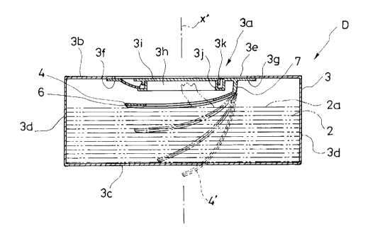
stacked body can also be configured by folding a long sheet that
has a plurality of lines of perforations extending along the width
direction of the long sheet. These lines of perforations are formed
at certain intervals in the lengthwise direction of the long sheet,
in which a section between adjacent lines of perforations is a single
1
CA 02905287 2015-09-10
wipe.
[0003] These wipes configuring the stacked body are connected
so that when the first wipe is pulled out, the second wipe follows.
Typically, the wipes are stacked in such a manner that the front
edge of the second wipe which is pulled by the first wipe is
positioned above the rear edge of the first wipe. In this design,
the front edge of the wipe located at the top of the stacked body
is lifted, allowing the front edge of this top wipe to be picked
up easily when pulled.
[0004] In some of the wipe dispensers of this type, the
dispenser opening of the storage body is structured to apply
resistance to the wipes passing therethrough, in order to prevent
two or more wipes from being pulled out of the storage body at the
same time (see Patent Literature 1 and Patent Literature 2, for
example). This structure separates the first wipe from the second
wipe when the first wipe is pulled out of the storage body, in which
when the front edge of the second wipe is lifted, this front edge
is prevented from sticking out of the storage body through the
dispenser opening.
[0005] However, the capacity of the storage body configuring
the wipe dispensers of this type is always greater than the volume
of the stacked body because the stacked body is stored in the storage
body. The difference between the capacity and the volume increases
as the number of wipes consumed increases. The invention disclosed
in Patent Literature 1, therefore, is not particularly inconvenient
when placed horizontally with its dispenser opening facing up, but
2
CA 02905287 2015-09-10
is not for vertical use with the dispenser opening facing sideways.
If the storage body is in the form of a pouch made of soft packaging
material, the shape-retaining ability of the storage body
deteriorates as the number of wipes consumed increases, because
the shape-retaining ability of the storage body is dependent on
the stacked body.
[0006] Moreover, owing to the effect of the fluid, the wipes
that are adjacent to each other vertically stick together tightly.
Particularly, even when the wipes are increasingly consumed, the
amount of this fluid does not easily decrease relative to the
consumption of the wipes. For this reason, the moisture content
of the wipes remaining in the storage body is likely to increase
as the number of wipes consumed increases, and therefore the
adhesion between the vertically adjacent wipes increases as the
number of wipes consumed increases. Consequently, the wipe
dispensers of this type are strongly required to be able to separate
a wipe from the subsequent wipe smoothly and more reliably.
[0007] Patent Literature 1: Japanese Patent Application
Publication No. 2012-206781
Patent Literature 2: Japanese Utility Model Application
Publication No. H1-178791
DISCLOSURE OF THE INVENTION
[0008] The first object of the present invention is to enable
a wipe dispenser of this type to be used vertically without causing
inconvenience, prevent the stacked body of wipes from becoming
3
CA 02905287 2015-09-10
untidy in the storage body of the wipe dispenser as much as possible,
and separate, smoothly and more reliably, a wipe from the subsequent
wipe while preventing as much as possible consumption of the wipes
from affecting the shape-retaining ability of the storage body.
[0009] The second object of the present invention is to provide
a wipe dispenser that is capable of separating a wipe from the
subsequent wipe as described above and at the same time moderately
lifting the front edge of the subsequent wipe.
[0010] The third object of the present invention is to provide
a wipe dispenser that can be manufactured smoothly and easily using
an automatic manufacturing machine, so as not to cause a pressing
member of the wipe dispenser to unnecessarily come into contact
and interfere with the other members when assembling the storage
body and an outlet member into the wipe dispenser or when packing
the stacked body of wipes in the storage body.
[0011] In order to achieve the first object, the present
invention is a wipe dispenser that has a stacked body configured
by stacking sheet-like folded wipes, a storage body for storing
the stacked body and having, at an upper portion, a dispenser opening
from which the wipes are pulled out, and a pressing member that
is pressed against an upper surface of the stacked body by biasing
force, wherein the pressing member ensures that resistance
generated when pulling the wipes through the dispenser opening is
uneven between a left-hand side and a right-hand side of the upper
surface of the stacked body, which is divided by a virtual straight
line therebetween that is perpendicular to a fold line of each of
4
CA 02905287 2015-09-10
the wipes.
[0012] In order to achieve the second object, the present
invention provides one favorable aspect of the wipe dispenser in
which the pressing member has an additional resistance application
portion that acts on the wipes being pulled. This additional
resistance application portion is formed of a large resistance
portion and a small resistance portion that each generate frictional
force in the passage of the wipes, the frictional force of the large
resistance portion being greater than that of the small resistance
portion. The large resistance portion is located, across the
virtual strait line, on the side where resistance induced by the
biasing force exists or on the side where the resistance is large.
[0013] In order to achieve the third object, the present
invention is the wipe dispenser that also has a retaining member
for keeping the pressing member in a state where the pressing is
pulled in a direction against the biasing force, the retaining
member being capable of releasing the pressing member from this
direction.
[0014] In another favorable aspect of this wipe dispenser
according to the present invention, the pressing member has one
end serving as a pressing portion that comes into abutment with
the upper surface of the stacked body, and has the other end
supported by an outlet member having a dispenser port for the wipes.
[0015] In another favorable aspect of this wipe dispenser
according to the present invention, the pressing member has one
end serving as a pressing portion that comes into abutment with
CA 02905287 2015-09-10
the upper surface of the stacked body, and is supported on the side
of the pressing portion by the outlet member having the dispenser
port for the wipes, via a momentum maintaining member, and the
additional resistance application portion is provided between the
pressing portion and the other end of the pressing member.
[0016] In another favorable aspect of this wipe dispenser
according to the present invention, the pressing member is supported
by the outlet member with the dispenser port for the wipes, via
momentum maintaining members disposed on the left-hand side and
the right-hand side with the virtual straight line therebetween,
and biasing force of the left-side momentum maintaining member is
different from that of the right-side momentum maintaining member.
[0017] According to the wipe dispenser of the present
invention, the function of the pressing member not only enables
convenient vertical use but also prevents the stacked body of wipes
from becoming untidy in the storage body. In addition, the function
of the pressing member can prevent the shape-retaining ability of
the storage body from being affected by the consumption of wipes,
and separates a wipe from the subsequent wipe smoothly and more
reliably.
[0018] According to the wipe dispenser of the present
invention, the function of the additional resistance application
portion can separate a wipe from the subsequent wipe as described
above and at the same time moderately lift the front edge of the
subsequent wipe.
[0019] The wipe dispenser according to the present invention
6
CA 02905287 2015-09-10
can be manufactured smoothly and easily using an automatic
manufacturing machine due to the function of the retaining member
that prevents the pressing member of the wipe dispenser from
unnecessarily coming into contact and interfere with the other
members when assembling the storage body and an outlet member into
the wipe dispenser or when packing the stacked body of wipes in
the storage body.
BRIEF DESCRIPTION OF THE DRAWINGS
[0020] Fig. 1 is a perspective configuration diagram showing
the exterior of a wipe dispenser (a first example) according to
an embodiment of the present invention;
Fig. 2 is a cross-sectional diagram, taken along line A-A of
Fig. 1;
Fig. 3 is a cross-sectional diagram, taken along line A-A of
Fig. 1, showing a state in which the wipes are consumed;
Fig. 4 is a perspective view showing an outlet member and a
pressing member that configure the first example;
Fig. 5 is a perspective view showing, from below, the outlet
. member and the pressing member that configure the first example;
Fig. 6 is a perspective configuration diagram showing the
pressing member and a stacked body that configure the first example;
Fig. 7 is a perspective configuration diagram showing a
partial modification of the configuration of the pressing member
of the first example;
Fig. 8 is a perspective configuration diagram showing a
7
CA 02905287 2015-09-10
pressing member and a stacked body that configure a wipe dispenser
(a second example) according to an embodiment of the present
invention;
Fig. 9 is a perspective view showing, from below, an outlet
member and a pressing member that configure a wipe dispenser (a
third example) according to an embodiment of the present invention;
Fig. 10 is a cross-sectional configuration diagram showing
principal parts of the third example;
Fig. 11 is a cross-sectional configuration diagram of a wipe
dispenser (a fourth example) according to an embodiment of the
present invention;
Fig. 12 is a perspective view showing, from below, an outlet
member and a pressing member that configure the fourth example;
Fig. 13 is a cross-sectional diagram of principal parts of
the fourth example, showing a state before an opening member is
removed;
Fig. 14 is a cross-sectional diagram of principal parts of
the fourth example, showing a state after the opening member is
removed;
Fig. 15 is a configuration diagram of the wipe dispenser that
has a stacked body of wipes folded into an alphabet letter Z;
Fig. 16 is a side configuration diagram showing a state in
which the wipe stacked at the top of the stacked body shown in Fig.
15 is started to be pulled out;
Fig. 17 is a side configuration diagram showing the step of
pulling out the wipe stacked at the top of the stacked body shown
8
CA 02905287 2015-09-10
in Fig. 15, the wipe being pulled out more than it is as shown in
Fig. 16;
Fig. 18 is a side configuration diagram showing the step of
pulling out the wipe stacked at the top of the stacked body shown
in Fig. 15, the wipe being pulled out more than it is as shown in
Fig. 17;
Fig. 19 shows a state in which the wipe following the wipe
stacked at the top of the stacked body shown in Fig. 15 is lifted
significantly when the wipe stacked at the top of the stacked body
is pulled out;
Fig. 20 is a side configuration diagram of a state in which
the wipe stacked at the top of the stacked body shown in Fig. 15
is started to be pulled out, showing a state in which resistance
is applied by the pressing member;
Fig. 21 is aside configuration diagram of the step of pulling
out the wipe stacked at the top of the stacked body, with the
resistance applied by the pressing member, showing a state in which
the wipe is pulled out more than it is shown in Fig. 20;
Fig. 22 is a perspective configuration diagram showing a state
in which the wipe that is stacked at the top of the stacked body
is about to be pulled out in which the resistance of the pressing
member is applied only to the right-hand side of an upper surface
of the stacked body, the right-hand side, along with the left-hand
side, having a virtual straight line therebetween which is
perpendicular to the fold lines of the wipes of the stacked body
and dividing the upper surface of the stacked body into two, the
9
CA 02905287 2015-09-10
right-hand side and the left-hand side;
Fig. 23 is a perspective configuration diagram showing a state
following the state shown in Fig. 22, in which the wipe stacked
at the top of the stacked body is still being pulled;
Fig. 24 is a perspective configuration diagram showing a state
following the state shown in Fig. 23, in which the wipe stacked
at the top of the stacked body is completely pulled out; and
Fig. 25 is a side configuration diagram showing a state
immediately before the wipe stacked at the top of the stacked body
is completely pulled out, the wipe being folded into an alphabet
letter W.
BEST MODE FOR CARRYING OUT THE INVENTION
[0021] A
typical embodiment of the present invention is now
described hereinafter with reference to Figs. 1 to 25. A wipe
dispenser D according to this embodiment has a stacked body 2
configured by sheet-like wipes 1, a storage body 3 that stores the
stacked body 2 and has, at its upper portion 3b, a dispenser opening
3a from which the wipes 1 are pulled out, and a pressing member
4 that is pressed against an upper surface 2a of the stacked body
2 by biasing force. The present specification illustrates a
typical form of using the wipe dispenser D in which the storage
body 3 is set up with the top wipe 1 of the stacked body 2 being
positioned on the top side of the wipe dispenser D (horizontal
use/see Fig. 1). In this typical form of using the wipe dispenser
D, the section on the top side is defined as the upper portion 3b
CA 02905287 2015-09-10
of the storage body 3 and the upper surface 2a of the stacked body
2, and the section on the bottom side is defined as a lower portion
3c of the storage body 3 and a lower surface 2b of the stacked body
2. When using the wipe dispenser D vertically, the upper portion
3b faces sideways. In the illustrated example, the stacked body
2 is in the shape of a hexahedron formed with the rectangular upper
and lower surfaces 2a and 2b. For convenience of explanation,
hereinafter, one of the large sides of this hexahedron is described
as "front side surface 2c" of the stacked body, the other one as
"rear side surface 2d" of the stacked body, one of the small sides
of the hexahedron that is located to the right of the front side
surface 2c as "right side surface 2e," and the other side located
to the left of the front side surface 2c as "left side surface 2f."
[0022] Figs. 1 to 3 each show an example of the storage body
3 made of soft packaging material such as a plastic film. The
storage body 3 has the upper portion 3b, the lower portion 3c, four
side portions 3d, configuring a hexahedral exterior. Although not
shown, the storage body 3 may be in the shape of a box made of plastic
or the like.
[0023] The dispenser opening 3a from which the wipes 1 are
pulled out is formed in the upper portion 3b of the storage body
3. In the illustrated example, the dispenser opening 3a is
configured with an opening 3e provided at the upper portion 3b of
the storage body 3 and an outlet member 3f attached on the inside
of the upper portion 3b of the storage body 3. Although not shown,
the outlet member 3f may be attached on the outside of the upper
11
CA 02905287 2015-09-10
portion 3b of the storage body 3.
[0024] The outlet member 3f has a base 3g larger than the
opening 3e and a lid 31 for closing a dispenser port 3h provided
on the base 3g. In the illustrated example, the outer rim of the
base 3g of the outlet member 3f is fixed to the rim surrounding
the opening 3e of the storage body 3 so that the opening 3e of the
storage body 3 can be closed by the outlet member 3f. By opening
the lid 3i, the front edge of the top wipe 1 of the stacked body
2 in the storage body 3 can be picked up through the dispenser port
3h, and this wipe 1 can be pulled out of the storage body 3.
[0025] In the illustrated example, the base 3g has, in an upper
surface thereof, a peripheral wall 3j surrounding the dispenser
port 3h, and the lid 31 has, in a lower surface thereof, a peripheral
wall 3k that is fitted to the peripheral wall 3j. The dispenser
port 3h can be kept closed by the lid 3i by fitting the peripheral
wall 3k to the peripheral wall 3j. In the illustrated example, the
lid 3i and the base 3g are integrated into a plastic molded article
with an elastically deformable hinge portion 3m therebetween. The
dispenser port 3h is opened by turning the lid 3i upward about the
hinge portion 3m with the amount of force enough to release the
peripheral walls 3j and 3k. Aside from the illustrated example,
when assembled, the lid 3i may be configured as a unit independent
from the base 3g that closes the dispenser port 3h.
[0026] In the illustrated example, the stacked body 2 is
configured by stacking a plurality of wipes 1 on top of each other,
the wipes 1 being folded along two or more fold lines la. Therefore,
12
CA 02905287 2015-09-10
the stacked body 2 is practically in the shape of a hexahedron.
The wipes 1 configuring the stacked body 2 are connected vertically
so that when the first wipe 1 is pulled out, the second wipe 1 follows.
In the illustrated example, the wipes I are stacked in such a manner
that a front edge lb¨ the leading end¨ of the second wipe 1, which
is pulled by the first wipe, is positioned above a rear edge lc
of the first wipe 1 (see Fig. 15).
[0027] In the illustrated example, the stacked body 2 has the
rectangular upper and lower surfaces 2a and 2b and the four side
surfaces (the front side surface 2c, the rear side surface 2d, the
right side surface 2e, and the left side surface 2f). (See Fig.
1) The fold lines la of each wipe 1 are parallel to the long sides
of the upper surface 2a and the lower surface 2b of the stacked
body 2, and the front side surface 2c and the rear side surface
2d are shaped by the fold lines la of the plurality of wipes 1 (see
Fig. 16).
[0028] Figs. 15 to 21 each show an example in which each of
the wipes 1 is folded into an alphabet letter Z along the two fold
lines la (referred to as "Z-folded" , hereinafter). In the stacked
body 2 configured by the Z-folded wipes 1, the fold line la in the
vicinity of the front edge lb of the second wipe 1 is located at
either the front side surface 2c or the rear side surface 2d of
the stacked body 2.
[0029] Fig. 25 shows an example in which each of the wipes 1
is folded into an alphabet letter W along the three fold lines la
(referred to as "W-folded," hereinafter). In the stacked body 2
13
CA 02905287 2015-09-10
configured with the W-folded wipes 1, when the fold line la in the
vicinity of the front edge lb of the second wipe 1 is located at
the front side surface 2c of the stacked body 2, the fold line la
in the vicinity of the front edge lb of the wipe 1 following the
second wipe 1 is located at the rear side surface 2d of the stacked
body 2.
[0030] The wipes 1 are typically created by impregnating
fabrics formed with paper, woven fabrics, non-woven fabrics or the
like of synthetic fiber or natural fiber, with a chemical solution.
Examples of the chemical solution include alcohols, water, and a
mixture thereof in which fragrances, antibacterial agents,
deodorants, surfactants, antiseptics, dyes, antifoaming agents,
antioxidants, clarifying agents, solubilizers and the like can be
blended, if necessary.
[0031] In the illustrated example, the pressing member 4 is
located between the outlet member 3f and the upper surface 2a of
the stacked body 2 and pressed against the upper surface 2a of the
stacked body 2 by biasing force.
[0032] In the wipe dispenser D according to this embodiment,
first of all, the pressing member 4 prevents the stacked body 2
configured by the wipes 1 from collapsing even when the wipe
dispenser D is used vertically with the dispenser opening 3a facing
sideways. Therefore, the wipe dispenser D can be used vertically
without any inconvenience. Second of all, the pressing member 4
can prevent the stacked body 2 configured by the wipes 1 from
becoming untidy in the storage body 3. Thirdly, the pressing member
14
CA 02905287 2015-09-10
4 can prevent as much as possible the shape-retaining ability of
the storage body 3 from being affected by the consumption of the
wipes 1.
[0033] In the illustrated example, the pressing member 4 is
supported by the outlet member 3f. The pressing member 4 may be
supported by the outlet member 3f at one area or two or more areas.
[0034] In the first example shown in Figs. 1 to 6, the pressing
member 4 is in a shape of a rectangular plate, the lower surface
of which comes into abutment with the upper surface 2a of the stacked
body 2. The wipes 1 configuring the stacked body 2 are each folded
into a rectangle, in which the fold lines la extend in the horizontal
direction as shown in Fig. 2. The pressing member 4 has its width
direction aligned perpendicular to the fold lines la of the wipes
1 and has one end serving as a pressing portion 6 abutting the upper
surface of the stacked body and the other end connected to the outlet
member 3f having the dispenser port 3h by a connecting portion 7.
Between the dispenser port 3h and one of the sides of the base 3g
of the outlet member 3f, the connecting portion 7 protrudes downward
from the lower surface of the base 3g that faces the stacked body
2, and is in the shape of a rib extending in a direction perpendicular
to the fold lines la of the wipes 1. The other end of the pressing
member 4 is integrated with the protruding end of the connecting
portion 7. In the first example, the pressing member 4 is integrated
with the outlet member 3f into a plastic molded article. The
pressing member 4 is located between the outlet member 3f and the
upper surface 2a of the stacked body 2 while being elastically
CA 02905287 2015-09-10
deformable so as to reduce the distance between the pressing portion
6 and the base 3g. The pressing member 4 elastically returns to
increase the distance between the free end 6 and the outlet member
3f as the number of wipes 1 consumed increases. In the first example,
the position shown by a numeral 4' in Fig. 2 represents the state
obtained before the pressing member 4 is elastically deformed.
Also in the first example, the pressing member 4 is bent, in which
the lower surface thereof is bent outward.
[0035] In this embodiment, the pressing member 4 ensures that
the resistance that is generated when the wipes 1 are each pulled
out of the dispenser opening 3a is uneven between the left-hand
side and the right-hand side of the upper surface 2a of the stacked
body 2 with a virtual straight line x therebetween, the virtual
straight line being perpendicular to the fold lines la of the wipes
1 (see Figs. 1, 6, 7 and 8).
[0036] As described above, when the first wipe 1 of the stacked
body 2 is pulled out, the second wipe 1 follows. Without the
pressing member 4, the front edge lb of the second wipe 1 is lifted
significantly (Fig. 19).
[0037] However, with the presence of the pressing member 4,
the resistance of the pressing member 4 acts on the front edge lb
of the second wipe 1. Therefore, the rear edge lc of the first wipe
1 can easily separated from the front edge lb of the second wipe
1, preventing the front edge lb of the second wipe 1 from being
lifted excessively (Fig. 21).
[0038] The resistance of the pressing member 4 is ensured to
16
CA 02905287 2015-09-10
be uneven between the left-hand side and the right-hand side with
the virtual straight line x therebetween. Therefore, starting from
the side where the resistance acts more, the separation between
the first wipe 1 and the second wipe 1 begins, and these wipes 1
continue to separate from each other in the remaining section. In
other words, the wipe dispenser D of this embodiment can smoothly
separate the first wipe 1 from the second wipe 1 (Figs. 22 to 24).
[0039] In the first example, the pressing portion 6 of the
pressing member 4 is in abutment with the upper surface 2a of the
stacked body 2 at the left-hand side with respect to the virtual
straight line x extending between the left-hand side and the
right-hand side as shown in Fig. 1 (see Fig. 2. In Figs. 2 and 10,
the virtual vertical plane having this virtual straight line x is
denoted by "x'"). In other words, in the first example, the
resistance of the pressing member 4 acts only on one of the sides
of the upper surface 2a of the stacked body 2 having the virtual
straight line x therebetween.
[0040] Moreover, an additional resistance application portion
8 that generates frictional force when the wipes 1 are pulled out
is formed in the pressing member 4. In other words, the wipes 1
are pulled out of the storage body 3 through this additional
resistance application portion 8 and the dispenser port 3h.
[0041] The additional resistance application portion 8 is
configured with a large resistance portion 8a and a small resistance
portion 8c that apply frictional force in the passage of the wipes
1, in which the frictional force of the large resistance portion
17
CA 02905287 2015-09-10
8a is greater than that of the small resistance portion 8c. In
addition to this, in the first example, the large resistance portion
8a is located on the side where resistance induced by the biasing
force is present, with the side having the virtual straight line
x therebetween.
[0042] In the
first example, the small resistance portion 8c
is practically configured by a circular hole that is big enough
to allow each of the wipes 1 to be picked up. The large resistance
portion 8a, on the other hand, is in the shape of a split groove
that has its groove end communicated with the small resistance
portion 8c and extends toward the pressing portion 6 of the pressing
member 4. The large resistance portion 8a has front and rear groove
edges along its extending direction and a plurality of sawtooth
edges 8b that are arranged in the horizontal direction with spaces
the rebetween.
[0043]
Therefore, in the first example, each of the wipes 1
passing through the additional resistance application portion 8
can be applied with large frictional force by the sawtooth edges
8b of the large resistance portion 8a at the pressing portion 6
side of the pressing member 4. With this mechanism, therefore, the
first wipe 1 and the second wipe 1 can reliably be separated from
each other. In addition, on the other side away from the pressing
portion 6 of the pressing member 4, the small resistance portion
8c allows the second wipe 1 to be lifted up moderately.
[0044] Fig. 7
shows a partial modification of the first example,
in which the lower surface of the pressing member 4 at the pressing
18
CA 02905287 2015-09-10
portion 6 side is bent inward.
[0045] In the
second example shown in Fig. 8, the pressing
member 4 has one end serving as a pressing portion 9 that comes
into abutment with the upper surface of the stacked body 2, and
is supported by the outlet member 3f with the dispenser port 3h
of the wipe 1 at the pressing portion 9 side via a momentum
maintaining member 10. An additional resistance application
portion 11 is disposed between the pressing portion 9 and the other
end of the pressing member 4. In the second example, the pressing
member 4 has a right side 12 parallel to the virtual straight line
x, front and rear sides 13 and 14 perpendicular to the right side
12, and a left side 15, and is configured by a plate in which the
left side 15 is in the shape of a semicircular arc extending along
a virtual arc, not shown. In the second example, the momentum
maintaining member 10 is in the shape of a strip in which its upper
end is integrated with the base 3g of the outlet member 3f and its
lower end integrated with the right side 12 of the pressing member
4. The
momentum maintaining member 10 has a plurality of fold lines
10a that are adjacent to one another extending along the width
direction and that are formed at certain intervals in the vertical
direction. With
the momentum maintaining member 10 bent
elastically along the plurality of fold lines 10a, the right side
of the pressing member 4 is brought into abutment with the upper
surface 2a of the stacked body 2 at the right-hand side with respect
to the virtual straight line x extending between the left-hand side
and the right-hand side. In this state, the pressing member 4 is
19
=
CA 02905287 2015-09-10
placed in the storage body 3 at a tilt, with the right side 12 being
at the lowest position and the left side 15 being at the top position.
In other words, in the second example, the right side 12 of the
pressing member 4 functions as the pressing portion 9. In the second
example, a groove end that is connected to the left side 15 is formed
in the pressing member 4. This forms a split groove extending toward
the pressing portion 9. This split groove has front and rear groove
edges along its extending direction in which a plurality of sawtooth
edges lib are arranged in the horizontal direction) with spaces
therebetween. In the second example, the wipes 1 can be pulled out
through the split groove of the pressing member 4 and the left side
15. In the second example, each of the wipes 1 passing through the
split groove can be applied with large frictional force by the
sawtooth edges llb at the pressing portion 9 side of the pressing
member 4. In other words, in the second example, the split groove
functions as a large resistance portion lla and the left side 15
of the pressing member 4 as a small resistance portion 11c.
[ 0046] In the third example shown in Figs. 9 and 10, the
pressing member 4 is supported by the outlet member 3f with the
dispenser port 3h of the wipe 1 via momentum maintaining members
16 on both the left-hand side and the right-hand side having the
virtual straight line x therebetween. In addition, the biasing
force of the momentum maintaining member 16 on the left-hand side
is different from the biasing force of the momentum maintaining
member 16 on the right-hand side. In the third example, the pressj,ng
member 4 is in a shape of a rectangular plate, the entire lower
CA 02905287 2015-09-10
surface of which comes into abutment with the upper surface 2a of
the stacked body 2. The pressing member 4 is connected to the base
3g of the outlet member 3f via the momentum maintaining members
16 on the right-hand side and the left-hand side with the dispenser
port 3h therebetween. The left and right momentum maintaining
members 16 each is in the shape of a strip in which the upper end
thereof is integrated with the base 3g and the lower end thereof
integrated with the upper surface of the pressing member 4. Each
of the momentum maintaining members 16 has a plurality of fold lines
16a which are adjacent to one another extending along the width
direction of each momentum maintaining member 16 and which are
disposed in the vertical direction with spaces therebetween. The
pressing member 4 has its lower surface in abutment with the upper
surface 2a of the stacked body 2 when elastically bent along the
plurality of fold lines 16a. In the third example, the width of
the right-side momentum maintaining member 16 is smaller than that
of the left-side momentummaintaining member 16. Thus, the biasing
force of the right-side momentum maintaining member 16 is smaller
than that of the left-side momentum maintaining member 16. In the
third example, therefore, the resistance of the pressing member
4 acts on both sides having the virtual straight line x therebetween
but prevents the biasing force on one of the sides having the virtual
straight line x therebetween from becoming equivalent to the biasing
force on the other side. In the third example, the pressing member
4 has a passage hole 17 for the wipes 1 that is elongated in the
horizontal direction. The rim of the passage hole 17 on the
21
CA 02905287 2015-09-10
right-hand side with respect to substantially the middle of the
pressing member 4 in its lengthwise direction is in the form of
an arc of a virtual ellipse. On the left-hand side, on the other
hand, the front and rear rims of the passage hole 17 configure a
plurality of sawtooth edges 18a that protrude inward and are
arranged in the horizontal direction with spaces therebetween. In
the third example, therefore, each of the wipes 1 is applied with
resistance by the sawtooth edges 18a on the left-hand side of the
passage hole 17 but does not receive such resistance on the
right-hand side of the passage hole 17. In other words, in the third
example, the right-hand side of the passage hole 17 of the pressing
member 4 functions as a small resistance portion 18c of an additional
resistance application portion 18, and the left-hand side of the
passage hole 17 functions as a large resistance portion 18a of the
additional resistance application portion 18. The large
resistance portion 18a is located on the side where the biasing
force-induced resistance is large, with the virtual straight line
x between the right-hand side and the left-hand side.
[0047] In the fourth example shown in Figs. 11 to 14, the wipe
1 dispenser D has a retaining member 24 for keeping the pressing
member 4 pulled in a direction against the biasing force. This
retaining member 24 is capable of releasing the pressing from this
direction. The fourth example is added with the retaining member
24 of the first example.
[0048] Fig. 11 is a cross-sectional diagram taken along line
AA of Fig. 1, showing a state before the wipe 1 dispenser D is used.
22
CA 02905287 2015-09-10
When the wipe 1 dispenser D is not used (i.e., prior to the use
of the wipe dispenser D), the dispenser port 3h is completely sealed
by an opening member 25 provided below the lid 3i, in order to prevent
the stacked body 2 from completely drying out in the storage body
3. The sealed state of the dispenser port 3h is cancelled by
removing the opening member 25 from the dispenser port 3h to the
outside.
[0049] The opening member 25 is integrated with the outlet
member 3f. A fragile portion 26 having a V-shaped cross section
is formed over the entire circumference of the outer periphery of
the opening member 25. A pull-top ring 27 that can be pulled outward
by a fingertip is integrated with the opening member 25.
[0050] In the unused state of the wipe 1 dispenser D in which
the opening member 25 is not yet removed from the dispenser port
3h, the dispenser port 3h is sealed with the opening member 25.
When the pull-top ring 27 is pulled outward, the fragile portion
26 collapses by shear failure and the opening member 25 is removed
to the outside, creating the state in which the wipes 1 can be pulled
out of the storage body 3 through the dispenser port 3h of the outlet
member 3f.
[0051] In the fourth example, the pair of retaining members
24 protrudes from the rear surface of the opening member 25 (i.e.,
the surface that faces the inside of the storage body 3) toward
the inside of the storage body 3. The retaining members 24 keep
the pressing member 4 pulled toward the outlet member 3f against
the biasing force, so that the pressing member 4 is not pressed
23
CA 02905287 2015-09-10
against the stacked body 2.
[0052] In the illustrated example, each of the retaining
members 24 is in the shape of a thin rod protruding from the rear
surface side of the opening member 25 and is connected to the opening
member 25, as shown in Fig. 12 and the like showing the back of
the pressing member 4. Specifically, the retaining members 24 of
this example are integrated with the opening member 25. Also, in
this example, these two retaining members 24 are formed at the front
and back, in which an engaging portion 24a that removably comes
into engagement with the rear surface of the rim of the pressing
member 4 in the lengthwise direction is formed at a tip of each
retaining member 24. Each of the engaging portions 24a is in the
shape of a hook in the illustrated example, but may be in any shape.
In the illustrated example, the engagement between the pressing
member 4 and the engaging portions 24a is released by elastic
deformation of the retaining members 24, by moving the retaining
member 24 to the outside by a certain distance.
[0053] As shown in Fig. 13, in the unused state in which the
opening member 25 is not yet removed, the engaging portions are
in engagement with the rim of the pressing member 4 along the
lengthwise direction, and keep the pressing member 4 pulled toward
the vicinity of the rear surface of the outlet member 3f against
the biasing force that tries to rotate the pressing member 4.
[0054] Such a configuration in which the pressing member 4 of
the wipe 1 dispenser D kept pulled toward the vicinity of the rear
surface of the outlet member 3f enables smooth execution of the
24
CA 02905287 2015-09-10
work processes in the process of manufacturing the wipe 1 dispenser
D. In other words, such a configuration can reduce the possibility
that the pressing member 4 might carelessly project toward the
inside of the storage body 3 during the work processes performed
after the pressing member 4 is kept pulled toward the vicinity of
the rear surface of the outlet member 3f. Therefore, the step of
fixing the storage body 3 and the outlet member 3f to each other,
the step of packing the stacked body 2 in the storage body 3 to
which the outlet member 3f is fixed, and various other steps can
be executed smoothly and easily using an automatic manufacturing
machine.
[0055] As shown in Fig. 14, by removing the opening member 25
to the outside in the beginning of the use of the wipe 1 dispenser
D, the engagement between the pressing member 4 and the engaging
portions 24a of the retaining members 24 integrated with the opening
member 25 is released. Consequently, the pressing member 4 is
turned toward the inside of the storage body 3 by the biasing force,
as shown by the arrow F in Fig. 14. As a result, when the wipe 1
dispenser D is being used, the pressing member 4 is pressed against
the upper surface 2a of the stacked body 2.
[0056] Although not shown, the retaining members 24 can each
be configured with an adhesive for adhering the rear surface of
the opening member 25 to the pressing member 4. In such a case,
the opening member 25 and the pressing member 4 are formed into
the shapes that enable the adhesion with the adhesive (e.g., in
the form of sheets, etc.). In the unused state of the wipe 1
CA 02905287 2015-09-10
dispenser D of this configuration in which the dispenser port 3h
is sealed with the opening member 25, the rear surface of the opening
member 25 and the pressing member 4 are adhered to each other, and
the pressing member 4 is kept pulled toward the vicinity of the
rear surface of the outlet member 3f. Then, once the opening member
25 is removed from the dispenser port 3h, the adhesion between the
opening member 25 and the pressing member 4 is released, pressing
the pressing member 4 against the stacked body 2.
[0057] The
present invention is not limited to the foregoing
examples and encompasses all the aspects included in the concept
of the present invention described in the claims.
26