Note: Descriptions are shown in the official language in which they were submitted.
CA 02905330 2015-09-10
WO 2014/150598
PCT/US2014/023755
SPECIFICATION
TITLE OF THE INVENTION
METHOD AND SYSTEM FOR MODIFYING A SOUND FIELD AT SPECIFIED
POSITIONS WITHIN A GIVEN LISTENING SPACE
RELATED APPLICATION INFORMATION
[0001] This application claims the benefit of U.S. Provisional Application
Serial No.
61/800,566, filed on March 15, 2013, hereby incorporated by reference as if
set forth
fully herein.
BACKGROUND OF THE INVENTION
1. Field of the Invention
[0002] The field of the invention pertains to sound reproduction systems
and, more
specifically, methods and systems for modifying audio signals from two or more
sound
sources creating a sound field within a bounded or semi-bounded listening
space to
achieve a desired sound field distribution between and within specified
listening
positions.
1
CA 02905330 2015-09-10
WO 2014/150598
PCT/US2014/023755
2. Background of Related Art
[0003] Audio systems are commonplace in households, automobiles and other
environments. Often, audio system components such as amplifiers and speakers
are
selected for certain desired characteristics such as high sound fidelity.
However, the
audio system components are only one factor affecting sound quality in a
particular
environment. Other factors include, among other things, the listening
environment itself,
the number and location of speakers, and the position of the listener.
[0004] For example, while many rooms are rectangular, usually one dimension
(length or width) is longer than the other, meaning that sound unfolds
differently across
the different dimensions of the room and may reflect at different times off
different walls.
This effect is more pronounced with rooms that are not perfectly rectangular
in shape. In
addition, the presence of openings or doorways in a room can affect the way in
which
sound is reflected or re-directed. Semi-bounded rooms or spaces, such as an
outdoor
stage, may have only one or two walls and hence quite asymmetric
characteristics for
sound reproduction. Also, the presence of objects or physical features within
the room or
listening space, or the existence of surfaces of different types (e.g.,
windows or hard
surfaces as compared to upholstery or soft surfaces) along the same or
different walls,
may also impact the way in which sound unfolds or is reflected within the
area.
[0005] In addition to the particular characteristics of the listening area,
the listener's
position within the room or listening space also influences the audio
experience and
determines the quality and characteristics of the sound experienced by the
listener. For
2
CA 02905330 2015-09-10
WO 2014/150598
PCT/US2014/023755
example, it is known that modes may exist within a room or other bounded area
at
wavelengths generally comparable to the dimensions of the length or width of
the room
or area. These modes may cause constructive or destructive interference that
and hence
create acoustic suppression at certain specific frequencies related to the
size (or shape) of
the room or other area. These modes are hard to predict for non-rectangular
rooms or
areas with odd shapes or physical obstructions. The number and placement of
speakers
will also affect what a listener experiences at a particular location in the
listening space.
Speakers closer to a listening position will generally be louder than speakers
farther
away, and thus, at different listening positions, the aggregate effect of
multiple speakers
may differ quite dramatically. Certain speakers, such as dipoles, also have a
directional
component, and hence the relative orientation of the listening position as to
the speakers
can, in some cases, also affect the listener's experience.
[0006] The above issues may manifest as a detectable difference in power
level over
one or more frequencies or frequency bands as between different listening
positions
within a prescribed listening area. Where such variability in power level
exists, the audio
system may be viewed as inefficient or wasteful, among other things, because
maximum
power is experienced in fewer than all listening positions.
[0007] An example of a bounded listening area presenting particular
challenges is the
enclosed space within an automobile or other vehicle where the listening
positions are
predetermined and suitable locations for the low frequency drivers are
restricted. In
addition, the listening positions are restricted to the seating positions
provided (usually 4
or 5) and all of these are very asymmetrically placed with respect to the
speaker
positions. Space is always at a premium within a car interior and as a result
the speakers
3
CA 02905330 2015-09-10
WO 2014/150598
PCT/US2014/023755
are often placed in physically convenient positions that are nevertheless
often very poor
from an acoustic point of view, such as the foot wells and the bottom of the
front and rear
side doors.
[0008] Some features are provided in automobile audio systems, or other
sound
systems, which can partially mitigate the aforementioned problems for one
listening
position but at the detriment of another. For example, an occupant can
manually adjust
the sound balance to increase the proportional volume to the left or right
speakers. Some
automobile audio systems have a "driver mode" button which makes the sound
optimal
for the driver. However, because different listening axes exist for left and
right occupants
or listeners, an adjustment to the balance that satisfies an occupant (e.g.,
driver) on one
side of the listening area will usually make the sound worse for the occupant
seated on
the other side of the listening area. Moreover, balance adjustment requires
manual
adjustment by one of the occupants or listeners, and it is generally desirable
to minimize
user intervention. Various types of equalization may also be used, but these
are typically
global in nature and hence do not adequately address the different experience
at different
listening locations. In addition, a global equalization may improve the sound
quality or
experience at one location, but be detrimental to the sound quality or
experience at other
locations in the listening space.
[0009] Other techniques propose moving speakers around to find optimal
speaker
locations, but those techniques are not effective when speaker locations are
fixed.
[0010] Similar asymmetries in sound experience and other related problems
may
occur in any other partially or wholly bounded listening space as well, such
as in
household rooms, auditoriums, arenas, and other defined listening areas. In
some cases
4
CA 02905330 2015-09-10
WO 2014/150598
PCT/US2014/023755
there is flexibility with respect to listening positions, but often the
listening positions are
generally fixed. Similarly, it is often the case that speaker locations are
fixed and hence
moving speakers is not an option.
[0011] In some cases, as opposed to the goal of having similar sound
quality and
level at the listening positions in a particular listening area, it may be
desirable to provide
different listening experiences for different occupants or listeners. For
example, it may
be desirable to have a quiet zone for one or more occupants, while maintaining
good
sound quality for the remaining occupants.
[0012] Accordingly, it would be advantageous to provide an improved sound
system
which overcomes one or more of the foregoing problems or shortcomings, and
which can
provide improved sound quality or selected sound field variability
SUMMARY
[0013] Embodiments of the invention may include, in one aspect, a technique
for
sound allocation within a prescribed listening area, such as an semi-bounded
or bounded
listening space. The sound allocation technique may be employed to minimize
variance
in frequency response or audio level at different listening positions whilst
optionally also
obtaining maximum output capability, or alternatively may be employed to
achieve a
desired sound level pattern or sound field variability while optionally
obtaining
maximum power output. The sound allocation technique may also be used to
achieve
particular zones of generally uniform frequency response (i.e., transfer
functions) or
audio level at a specified listening position.
CA 02905330 2015-09-10
WO 2014/150598
PCT/US2014/023755
[0014] In a first aspect, an audio system with predefined speaker locations
may be
configured to achieve maximum or optimal power output with minimum variance
(within
a selected tolerance, for instance) at the listening positions.
[0015] In another separate aspect, an audio system with predefined speaker
locations
may be configured to achieve maximum or optimal power output when producing a
desired sound level pattern or sound field variance.
[0016] In yet another separate aspect, an audio system with predefined
speaker or
acoustic output source locations may be configured to produce zones of uniform
frequency response or audio level within a prescribed listening space, such as
a bounded
or semi-bounded listening area.
[0017] According to one or more embodiments as disclosed herein, an audio
system
with predefined acoustic output source (e.g., speaker) locations includes a
sound
allocation processor that modifies the signal sent to each speaker so that the
vector sum
of the all of the sound sources gives desired response characteristics at each
listening
position. The technique is generally applicable to any type of speakers,
whether
directional or not, and including monopole or dipole speakers for example.
[0018] Further embodiments, variations and enhancements are also
disclosed
herein
BRIEF DESCRIPTION OF THE DRAWINGS
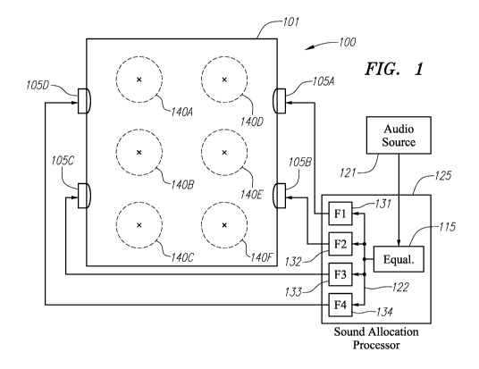
[0019] FIG. 1 is a diagram of an embodiment of a sound allocation system
in
accordance with one embodiment as disclosed herein.
6
CA 02905330 2015-09-10
WO 2014/150598
PCT/US2014/023755
[0020] FIG. 2 is a flow diagram illustrating a process for sound
allocation in
accordance with one example as described herein.
[0021] FIG. 3 is a top diagram illustrating an example of sound
measurement
locations for determining the sound reproduction characteristics of a
listening area
relative to different listening locations.
[0022] FIG. 4 illustrates a possible implementation of a sound allocation
processor as may be used in connection with a sound allocation system in
accordance
with one or more embodiments as disclosed herein.
[0023] FIG. 5 is a conceptual diagram showing how the aggregate modified
speaker outputs combine at each listening position within a listening area to
generate a
modified sound field or frequency response at each listening position,
according to one
example.
[0024] FIG. 6 is a diagram illustrating a bounded listening area with a
set of
speakers, and various graphs illustrating examples of sound measurements taken
at
specified listening positions in the listening area.
[0025] FIG. 7 is a diagram illustrating the same listening area as in
FIG. 6, but
with sound allocation as provided according to an example herein, and
accompanying
graphs showing modified audio characteristics or frequency responses at each
of the same
listening positions after the modified sound signals are played through the
various
speakers.
7
CA 02905330 2015-09-10
WO 2014/150598
PCT/US2014/023755
DETAILED DESCRIPTION OF PREFERRED EMBODIMENTS
[0026] According to one or more aspects of embodiments disclosed herein, an
audio
system is provided having a plurality of acoustic output sources disposed in
or around a
listening area, with a sound allocation processor receiving an audio source
signal. The
sound allocation processor may include a plurality of audio modifying
elements, one for
each acoustic output source, modifying certain characteristics (e.g., a gain
and/or a phase)
of the audio source signal with respect to frequency for each acoustic output
source to,
for example, create a uniform sound level over the listening area or within
defined zones
within the listening area. The sound allocation processor may, in certain
circumstances,
be configured to maximize or optimize the output capability the acoustic
output sources
whilst at the same time minimizing the inter-seat response variability and the
in-band
response uniformity, within a selected tolerance.
[0027] In various embodiments, each of the audio modifying elements may
comprise
one or more custom filters for each acoustic output source, and may optionally
further
include a custom gain stage for each acoustic output source. The audio
modifying
elements may, for example, include a delay and/or non-minimum phase shift
adjustment
that is specifically tailored for each speaker or sound source. In addition,
the sound
allocation processor may comprise a global equalization adjustment applied to
the audio
source signal for all of the acoustic output sources.
8
CA 02905330 2015-09-10
WO 2014/150598
PCT/US2014/023755
[0028] In a preferred embodiment, the acoustic output sources include low
frequency
drive units, and the sound allocation processor is configured to affect
primarily low
frequencies of the audio source signal.
[0029] In another separate aspect, a method for sound allocation in an
audio system is
provided, comprising receiving an audio source signal and, for each of a
plurality of
acoustic output sources, independently modifying a gain and/or a phase of the
audio
source signal with respect to frequency to create a substantially uniform
sound level or a
desired sound field variability over the listening area or within defined
zones within the
listening area. The modified audio source signals are then conveyed to each
respective
acoustic output source.
[0030] According to another separate aspect, a method for sound
modification in an
audio system having a plurality of acoustic output sources in or around a
prescribed
listening area, comprises the steps of characterizing a sound transfer
function for each of
the acoustic output sources, and employing an annealing algorithm to identify
parameters
providing a specified sound level variance at defined listening positions
within the
listening area. The identified parameters may be durably stored in the audio
system for
future use, and may later be utilized in the audio system to modify an audio
source signal
so as to achieve the specified sound level variance within the listening area.
[0031] In certain embodiments, the identified parameters are applied to
adjust a gain
and/or a phase of different spectral components independently for each of the
acoustic
output sources. One or more custom filters as well as a custom gain for each
acoustic
output source may be used to independently modify the audio source signal for
that
acoustic output source. The identified parameters may include a speaker-
specific delay
9
CA 02905330 2015-09-10
WO 2014/150598
PCT/US2014/023755
and/or a non-minimum phase shift as applied separately and independently to
each
speaker or sound source.
[0032] In a preferred embodiment, as explained in greater detail herein,
the annealing
algorithm may involve selecting candidate sound modification parameters for
each
acoustic output sources, applying the sound modification parameters to
determine a
sound output level at the defined listening positions within the listening
area; and
determining a variance in sound output level between the different listening
positions. If
the variance in sound output is within a specified tolerance, the candidate
sound
modification parameters may be accepted. The sound modification parameters may
include a selected gain associated with each acoustic output source, and/or a
selected
phase for different spectral components associated with each acoustic output
source. For
example, the selected phase adjustment may involve a frequency-dependent phase
pattern
using a component providing a non-minimum phase shift.
[0033] According to certain embodiments, a sound allocation technique is
provided
that may maximize or optimize the output capability in an audio system. The
sound
allocation technique may also or alternatively, for example, minimize sound
variation
among different listening positions, within a selected tolerance, or produce a
desired
sound level pattern or sound field variability. The sound allocation technique
may also
be used to create "relatively quiet spots" or "relatively quiet zones" and/or
produce zones
of uniform frequency response or audio level within a prescribed listening
space. These
quiet zones may have a specified sound level reduction as compared to other
areas of the
prescribed listening space. Conversely, the sound allocation processor may be
used to
CA 02905330 2015-09-10
WO 2014/150598
PCT/US2014/023755
create zones of relatively boosted sound or volume level, having a specified
sound level
increase as compared to other areas of the listening space.
[0034] The sound allocation techniques and related embodiments described
herein
may find particularly advantageous use for listening spaces in which the
wavelength at
the maximum frequency of interest subject to processing are greater than
1/10th of the
maximum dimension of the listening space. For example, for an automobile
interior as
the listening area, it may be desirable to perform the disclosed sound
processing on
frequencies in and below the neighborhood of 200 Hertz, which corresponds to
wavelengths in the range of roughly 5-6 feet. In other embodiments, such as
for
residential rooms of ordinary size, the sound processing may be performed
primarily in
the low frequency range, below some selected threshold such as below 400
Hertz, below
250 Hertz, or 150 Hertz. Conversely, for smaller enclosed spaces, such as a
telephone
booth for example, the sound processing may be performed over a larger or
higher
frequency range, such as up to 1 kHz or 2 kHz for instance.
[0035] In an embodiment in which level allocation is applied by an audio
sound
system, a set of four low frequency drive units at predefined locations within
an enclosed
listening space are provided with processed audio signals in order to provide
near
constant sound levels across frequencies or a desired sound field variability
at different
listing positions within the enclosed space.
[0036] Although one or more preferred embodiments are described having four
low
frequency drive units, it is to be understood that such a configuration is
merely
exemplary. Embodiments of the invention can be practiced with a fewer number
(e.g.,
two or three) low frequency drive units, or a greater number, or with other
types of sound
11
CA 02905330 2015-09-10
WO 2014/150598
PCT/US2014/023755
sources having characteristics of a monopole, dipole or combination thereof as
well of
any arbitrary number so long as the number of speakers is sufficient to create
the desired
sound level pattern or sound field variability. The sound allocation is
preferably
performed over non-directional frequency bands such as the frequency band
below 200
Hertz; thus, the speakers or other sound sources are optimally, but need not
be, low
frequency drive units.
[0037] Fig. 1 shows an embodiment of a sound allocation system 100 in
accordance
with one aspect of the instant disclosure. In Fig. 1, an audio source 121
provides an
audio signal 122 to an audio sound allocation processor 125 which, as
explained in more
detail below, individually modifies the sound for each of a plurality of
speakers in a
bounded or enclosed listening area 101. The audio source 121 may include or be
derived
from any source of audio content, such as, for example, a conventional radio
(including
FM, AM or satellite radio), a CD player, an MP3 player or source, a DVD
soundtrack, or
any other source of audio content. The audio source 121 may also include other
audio
components, such as amplifiers or pre-amplifiers, equalizers, filters, and the
like.
[0038] As further illustrated in Fig. 1, a set of speakers 105A ¨ 105D
(which, in this
example, are four in number, although the invention may be practiced with any
number
of two or more speakers or other acoustic output sources), which may be
monopole or
dipole sources or a combination thereof, are spaced about the bounded or
enclosed area
101. While in this example the speakers 105A ¨ 105D are spaced symmetrically
around
the bounded area 101, this configuration is not a requirement. An audio input
signal 102
is supplied to an audio sound allocation processor 125 which, as described in
more detail
hereafter, provides individualized modifications to the phase and/or amplitude
of the
12
CA 02905330 2015-09-10
WO 2014/150598
PCT/US2014/023755
audio input signal 102 in order to provide more balanced and even sound at
selected
listening positions, or else to provide a sound field of a particular shape or
characteristics
over a selected range or band of frequencies. The audio sound allocation
processor 125
includes audio modifying elements 131 ¨ 134 which adjust the phase and/or
amplitude of
audio input signal 102 respectively for each of speakers 105A ¨ 105D, which
are fed by
audio signals 107A ¨ 107D, respectively, output by audio modifying elements
131 ¨ 134.
The nature of audio modifying elements 131 ¨ 134 is discussed by way of
illustrative
examples below.
[0039] According to one embodiment that may be implemented in accordance
with
the example shown in Fig. 1, the audio sound allocation processor 125 modifies
the phase
and/or amplitude of the complex spectra associated with the audio speaker
outputs in
order to achieve a substantially uniform audio level at the various listening
positions, or a
sound field variability pattern of desired properties, while seeking to
maximize total
audio output. In this example, the audio sound allocation processor 125 is
configured to
provide a substantially uniform audio level or sound field pattern at six
primary listening
positions 140A ¨ 140F, although any number of listening positions may be
selected.
[0040] According to another embodiment that may be implemented in
accordance
with the example shown in Fig. 1, the audio sound allocation processor 125
modifies the
phase and/or amplitude of the complex spectra associated with the audio
speaker outputs
in order to reallocate or readjust the sound levels across different
frequencies within a
bounded or semi-bounded listening space 101. In this embodiment, the audio
sound
allocation processor 125 may provide different sound experiences at different
listening
positions; for example, it may be employed to create a "hole" or "dead zone",
i.e., a zone
13
CA 02905330 2015-09-10
WO 2014/150598
PCT/US2014/023755
of relative quiet, in the overall sound field at the location of one or more
of the primary
listening positions 140A ¨ 140F. This type of operation can be advantageous,
for
example, where one or more of the listeners do not want to hear the audio
content.
[0041] In either embodiment, the audio modifications described herein may
be
provided on an ongoing basis, or may be applied dynamically for particular
situations.
[0042] An illustration of one technique for sound level allocation is
illustrated in the
flow diagram 200 of Fig. 2, which may be explained by way of example with
reference to
the audio system 100 illustrated in Fig. 1 which, in this case, includes four
speakers 105A
¨ 105D although, as noted earlier, the process may work with any arbitrary
number of
speakers of sufficient quantity to suitably effect the listening area. As
shown in Fig. 2,
the process 200 begins with a first step of selecting a set of listening
positions within an
enclosed or bounded listening space (e.g., area 101 shown in Fig. 1), as
represented by
block 205 in Fig. 2. By way of example, the six listening positions 140A ¨
140F may be
selected. While in this example, six listening positions 140A ¨ 140F are
selected, any
number of listening positions may be chosen. Next, sound measurements are
taken in
order to characterize the unmodified sound field in the absence of audio
processing as
described herein. These sound measurements may involve obtaining a spectral
profile of
the speaker output at each measurement location, characterized in the form of
a complex
transfer function, using any of the well-known methods for measuring the
complex
transfer function between a sound source and receiver. The sound measurements
may be
taken for each speaker independently, and may be made at only the listening
positions or
else at other locations in the listening area as well, as illustrated in FIG.
3 for example
14
CA 02905330 2015-09-10
WO 2014/150598
PCT/US2014/023755
(measurements taken at locations 310A-C, 315A-C, 320A-C, 325A-C, 330A-C, and
335A-C).
[0043] Once the sound measurements have been taken for each speaker 105A ¨
105D
in the current example (i.e., with the sound measurement pattern of Fig. 3),
the sound
measurements at a given listening position or other sound measurement point
are
summed vectorially for each of the sound measurement points, preferably
characterized
in the form of a composite transfer function at each sound measurement point
[0044] Next, as illustrated in the following steps in Fig. 2, a sound
allocation
algorithm is run on the composite sound profiles 219 in order to generate
parameters to
be used with audio electronic equipment in order to create a modified sound
field or
sound level pattern following certain desired characteristics. In this
example, as an initial
aspect of the sound allocation algorithm (as indicated by step 235), a
tolerance value may
be selected (in terms of dB, percent, or other value) by which the sound
levels at the
various listening positions or other sound measurement locations may be
compared. The
selected tolerance value will affect how many candidate solutions are
generated, and is
preferably set so that a meaningful set of candidate solutions is obtained.
[0045] In a next step 240, a search is run in order to identify a candidate
set of
solutions to achieve a desired sound level allocation over a given range of
frequencies.
The desired sound level pattern may be one, for example, that is as even or
uniform as
possible across the different listening positions. Alternatively, the desired
sound level
pattern or sound field variability pattern may be one in which certain
listening positions
have a drop off in sound level or are substantially quiet. A multivariate
algorithm may
employed to select different phase and/or amplitude adjustment values for each
speaker
CA 02905330 2015-09-10
WO 2014/150598
PCT/US2014/023755
105A ¨ 105D, using the composite transfer functions to determine the predicted
output at
each listening position or sound measurement location. If too many candidate
solutions
are obtained during the process, then the tolerance value may be tightened in
order to
reduce the number of possible solutions.
[0046] A candidate solution may be tested to determine whether the modified
sound
level pattern is relatively even across the different listening positions,
i.e., the predicted
sound output is within the selected tolerance across the different listening
positions
(assuming the goal is to make the sound levels even across the listening area)
over the
desired frequency range, as indicated by step 250. The smoothness or
uniformity of the
sound field, either globally or within a selected sound zone, may be evaluated
by, e.g.,
looking at the standard deviation of the combined sound output at each of the
listening
positions or sound measurement points. The process compares the predicted
sound
output at each of the different listening positions or sound measurement
points with one
another to see if the sound output is within the selected tolerance. If not,
then the
candidate solution is discarded (step 251). Otherwise, the candidate solution
is tested to
see if the predicted sound output is relatively smooth over the desired
frequency range, as
indicated by step 255. If not, then the candidate solution may be discarded
(step 251).
Alternatively, steps 250 and 255 may be replaced by steps that test whether
the candidate
solution is one which provides a sound level pattern or sound field
variability of desired
shape, and those that deviate from the desired shape by more than a selected
tolerance
may be discarded.
16
CA 02905330 2015-09-10
WO 2014/150598
PCT/US2014/023755
[0047] If no candidate solutions are obtained by the above process, the
tolerance may
have been set too tight. In such a case, the tolerance may be increased and
another
attempt made to identify candidate solutions.
[0048] To create a "relatively quiet zone" in a particular location within
the
prescribed listening area, it is possible to apply an error weighting function
to the
measurement points in the quiet zone area in order to reduce the sound output
within that
zone. For example, an error weighting function may be applied in the quiet
zones so that
the sound produced by the collective sound sources will be suppressed by, for
example,
10dB or 20dB within that region whilst retaining the same frequency response
and seat to
seat variation. In terms of running the above candidate solutions, the inverse
of the
weighting function, i.e., +10 dB or +20 dB, would be added to the measured
values at the
sound measurement points. Then, when the candidate solutions are tested to
determine
the predicted sound output, the actual sound output in the "relatively quiet
zones" will
actually be less by the value of the error weighting function.
[0049] In one embodiment, a converging algorithm may be employed to
identify
candidate solutions by perturbing the phase and/or amplitude individually for
each of the
speakers and predicting the sound output at the different sound measurement
points, over
the frequencies of interest, by using the measured transfer functions. In
particular, an
annealing algorithm may be employed to identify candidate solutions and
converge on a
best fit candidate. An annealing algorithm has the benefit of being more
likely to avoid
local minima and instead identify a solution that constitutes a global minimum
variance.
Annealing algorithms are known generally in the art and are used, for example,
in aircraft
for noise reduction.
17
CA 02905330 2015-09-10
WO 2014/150598
PCT/US2014/023755
[0050] As represented now in step 260, the best result from the candidate
set of
solutions is identified. This may be carried out as a discrete step or part of
the
converging algorithm that is employed to identify candidate solutions. The
best
candidate may be one that, through an added global equalization, may be
suitable to
achieve the desired pattern of sound levels and characteristics. The sound
level pattern or
sound field shape and structure may include desired zones of generally or
substantially
uniform frequency response, created in part by utilizing both destructive and
constructive
interference in combination. In some cases, the best result from the candidate
set of
solutions is one which mitigates losses through destructive interference,
evens the load as
much as possible on all of the speakers or other sound sources, and/or reduces
peaks and
dips in local zones within the target listening area or globally therein.
[0051] Assuming a suitable solution has been determined, in a next step
270, an
audio modifying element implementation is selected for each speaker. Thus, in
the
example of Fig. 1, an implementation would be selected for audio modifying
elements
131 ¨ 134 that supply audio signals to speakers 105A ¨ 105D. A variety of
different
types of electronic components or filters may be utilized for this purpose.
For example,
the required equalization may be implemented by using any combination of
finite
response filter (FIR), infinite impulse response (IIR) filters having minimum
phase or
non-minimum phase, or other types of filters, in conjunction optionally with a
delay
element and/or a gain adjustment applicable to the particular speaker. The
audio
modifying elements 131 ¨ 134 each apply the phase and/or amplitude adjustment
that had
been determined for the best solution to providing the desired sound field
according to
18
CA 02905330 2015-09-10
WO 2014/150598
PCT/US2014/023755
the previously run search algorithm. In certain embodiments, only amplitude
adjustment
may be utilized, or only phase adjustment may be utilized.
[0052] In a next step 280, a global equalization characteristic may be
selected for the
audio sound allocation processor 125. The global equalization collectively
adjusts all of
the signals fed to speakers 105A ¨ 105D so that the actual sound level pattern
or sound
field better matches the desired sound pattern or field. Since the sound level
at each
listening position is selected by the earlier process to be substantially
identical within a
given tolerance (assuming a sound zone or region with generally uniform or
even
frequency response or audio level is desired as opposed to one varying in
frequency
response or audio level at different listening positions), a global
equalization should not
change the fact that the relative sound level should remain approximately the
same at
each listening position. The global equalization characteristic may be
implemented as a
separate component within the audio sound allocation processor 125.
[0053] Figure 4 illustrates a preferred implementation of a sound
allocation system
400 in accordance with one embodiment as disclosed herein. Although the
embodiment
of Fig. 4 is similar to Fig. 1 in that it uses four speakers 404A ¨ 404D, any
number of two
or more speakers may be used. As illustrated in Fig. 4, the sound allocation
system 400
in this example comprises an audio sound allocation processor 425 that is
includes or is
coupled to an audio source 421, similar to audio source 121 described
previously in
reference to Fig. 1. The audio source 421 provides an audio signal to an
equalizer 415,
which applies a global equalization to the audio signal 422 that is ultimately
fed, in
modified form, to each of speakers 405A ¨ 405D.
19
CA 02905330 2015-09-10
WO 2014/150598
PCT/US2014/023755
[0054] The output of the equalizer 415 is provided delay elements 431 to
434 which
may apply delay adjustment that is individualized for each speaker 405A -
405D. The
output of the delay stages 431 - 434 are provided to filter stages 441 ¨ 444,
respectively,
each of which outputs one of a set of modified audio signals 481 ¨ 484 to
speakers 405A
¨ 405D, respectively. Filter stages 441 ¨ 444 preferably are embodied or
include a non-
minimum phase shift adjustment element, although they may generally comprise
one or
more low-pass filters, high-pass filters, bandpass filters, bandstop filters,
shelf filters,
non-minimum phase components, or other types of filters or elements. Filter
stages 441 ¨
444 may be implemented as FIR or IIR filters, for example, or in other
manners.
[0055] For purposes herein, a difference between a minimum phase shift
filter and a
non-minimum phase shift filter may be described as follows. A minimize phase
shift
filter is generally described by the transfer function:
F'W
10). õ...s=
and which does not have zeros in the right half s plane. If, on the other
hand, a filter's
transfer function has zeros in the right half s plane, then it would exhibit
non-minimum
phase behavior. The modulus of the phase response for a non-minimum phase
shift filter
is larger than that for a filter with minimum phase behavior having the same
amplitude
response.
[0056] Each speaker 405A ¨ 405D receives an output from one of the filter
stages
441 ¨ 444, and thereby receives an audio signal that is modified in terms of
phase and/or
gain in order to contribute to a desired sound level pattern or sound field.
FIG. 5 is a
CA 02905330 2015-09-10
WO 2014/150598
PCT/US2014/023755
conceptual diagram showing how the aggregate modified speaker outputs combine
at
each listening position M1 ¨ M4 within the listening area to generate a
modified sound
field or frequency response at each listening position, according to one
example. For
example, at listening position Ml, the outputs form speakers 405A ¨ 405D
combine such
that their aggregate outputs form a combined transfer function at listening
position Ml,
according to the vector sum of all of the speaker outputs. A similar effect
occurs at
listening positions M2, M3 and M4, but in each case dependent upon the
relative audio
level and characteristics of each speaker output as perceived at the
particular listening
position.
[0057] Of course, the invention disclosed herein is not limited to the
particular
configuration illustrated in Fig. 4, and many other implementations are
possible as would
be understood by those skilled in the art.
[0058] In one or more embodiments, the speakers 105A ¨ 105D may be low
frequency drive units, and the adjustments or modifications provided by the
sound
allocation processor may effectuate an even bass response across a plurality
of listening
positions.
[0059] In some cases, such as where the speakers 105A ¨ 105D are located in
an
automobile, the listener can make manual adjustments to the relative volume
levels as
amongst the speakers, for example by adjusting a fade control (which adjusts
the relative
volume as between front and back speakers) or a balance control (which adjusts
the
relative volume as between right and left speakers). Manual adjustments to the
relative
speaker volume levels through fade or balance controls may affect the sound
allocation
provided by the sound allocation processor. To adjust for the changes in
relative volume,
21
CA 02905330 2015-09-10
WO 2014/150598
PCT/US2014/023755
it is possible to provide different parameters for the audio modifying
elements 131 ¨ 134
for different levels of fade and/or balance. For example, different filter
parameters may
be provided at discrete fade and/or balance levels. Such parameters may be
stored, for
instance, in a lookup table within the sound allocation processor 125, and
loaded into the
audio modifying elements 131 ¨ 134 in real time as the manual fade and/or
balance
adjustments are made. There may be one lookup table for different fade levels
and one
lookup table for different balance levels, or else the parameters may be
combined into a
single two-dimensional lookup table that uses both the fade and balance levels
as
selection inputs.
[0060] An example of a sound allocation process as applied to a
particular
listening area may be explained with respect to FIGS. 6 and 7. FIG. 6 shows a
top view
of a bounded listening area 601 with designated listening positions 640A-D
(also
designated as M1 ¨ M4) and speakers 605A-D at the specified locations near the
corners
of the listening area 601. In this example, the set of speakers 605A-D, which
may be
low frequency drivers or subwoofers, are located at various fixed positions in
the
listening area 601. All speakers 605A-D are driven equally, i.e., they each
receive the
same audio source signal (whether from one amplifier or multiple amplifiers).
Notably,
the listening positions 640A-D need not be symmetrical throughout the room,
although
they could be; this is a matter of design and implementation choice. Also
shown in FIG.
6 are graphs 650, 660, 670 and 680 that show, for each location M1 ¨ M4, a
respective
frequency response curve that depicts for each location the difference in
response from
the mean or average response for all locations. It can be seen for example
that at roughly
45 Hz, there is up to 15dB variation in response between the four locations.
This is
22
CA 02905330 2015-09-10
WO 2014/150598
PCT/US2014/023755
generally undesirable from the standpoint of providing a uniform listening
experience
regardless of listening position.
[0061] FIG. 7 shows the same arrangement of listening area 601, speaker
and
listening positions, but with the speakers 605A-D driven by a sound allocation
processor
725 utilizing techniques as previously described herein and, more
specifically, that has
been configured to apply gain and/or phase adjustments independently for each
speaker
over the frequency range of interest (in this case, below 100 Hertz), after
employing a
search algorithm or related technique to arrive at suitable parameters for the
sound
allocation processor 725. The sound allocation processor 725 receives an audio
signal
from an audio signal source 721, and then uses audio modifying components 731
¨ 734 to
separately modify the spectral characteristics of the audio source signal
individually for
each of the speakers 605A-D, by for example adjusting a gain and/or phase of
the audio
source signal individually for each speaker 605A-D. As noted previously, the
sound
allocation processor 725 may also apply a global equalization adjustment 715
for all of
the speakers 605A-D. The accompanying graphs 750, 760, 770, 780 correspond to
graphs 650, 660, 670, 680 respectively in FIG. 6, and show that the deviation
from the
mean response is greatly reduced by the action of the sound allocation
processor 725.
Thus, the operation of the sound allocation processor 725 in accordance with
the
principles described herein may act to provide a substantially uniform sound
level across
different listening positions, through means of audio processing and without
necessarily
requiring a change in the speaker positions.
[0062] According to one or more aspects as disclosed herein, a sound
allocation
system comprises a plurality of speakers disposed around a bounded or semi-
bounded
23
CA 02905330 2015-09-10
WO 2014/150598
PCT/US2014/023755
listening area, an audio source coupled to a sound allocation processor, said
sound
allocation processor comprising individualized sound modification components
for each
speaker, wherein the sound modification components adjust the transfer
function
individually for each speaker to obtain a desired sound level pattern or sound
field
variability within the listening area, with respect to a particular frequency
range or band
of interest. In one or more embodiments, the sound modification components are
selected so that the sound level is substantially identical, within a selected
tolerance and
over a desired frequency range, at each of a plurality of listening positions.
In other
embodiments, the sound modification components are selected so that the sound
level
matches a desired non-uniform sound allocation pattern over a desired
frequency range
across a plurality of listening positions.
[0063] In one aspect, an audio system is provided having predefined speaker
locations that achieves maximum or optimal power output with minimum
detectable
variance (within a given tolerance) at a plurality of listening positions over
a desired
frequency range. In another separate aspect, an audio system is provided
having
predefined speaker locations that achieves maximum or optimal power output
while
producing a desired non-uniform sound level pattern or sound field variability
in the
listening area, over a desired frequency range.
[0064] While preferred embodiments of the invention have been described
herein,
many variations are possible which remain within the concept and scope of the
invention.
Such variations would become clear to one of ordinary skill in the art after
inspection of
the specification and the drawings. The invention therefore is not to be
restricted except
within the spirit and scope of any appended claims.
24