Note: Descriptions are shown in the official language in which they were submitted.
CA 02905542 2015-09-10
WO 2014/144894 PCT/US2014/029489
METHODS AND SYSTEMS FOR CONDITIONING OF
PARTICULATE CRYSTALLINE MATERIALS
BACKGROUND
Technical Field
[0001] This disclosure relates generally to systems and methods for the
preparation and stabilization of particulate materials. More specifically,
this
disclosure relates to systems and methods for conditioning particulate
materials
to improve the physicochemical stability of the materials as well as
compositions incorporating such particles.
Description of the Related Art
[0002] Particulate crystalline materials, including micronized
crystalline
particulates, are useful in a variety of contexts. For example, certain
industrially
useful compounds are conveniently stored in bulk as dry, particulate powders.
Additionally, certain compounds can be better utilized or incorporated into
commercial products when provided as micronized crystalline particulates. This
can be seen with pharmaceutically active compounds that exhibit improved
formulation, delivery, or therapeutic attributes when provided in micronized
crystalline form.
[0003] However, processes used to produce certain crystalline materials
can result in material characteristics that introduce an undesired level of
physiochemical instability. Techniques for nnicronization of crystalline
material
often utilize energy-intensive milling, grinding, shearing or particle-to-
particle
collisions to reduce particle size. An example of one such technique is air
jet
milling, which uses high velocity air or gas to cause particle-to-particle
collisions
and to generate micronized material, including particles ranging from about
0.5
to about 30 pm in diameter. The exertion of thermal or mechanical energy
during energy-intensive micronization processes can cause the formation of
non-crystalline, amorphous material that can lead to significant
physicochemical
1
CA 02905542 2015-09-10
WO 2014/144894 PCT/US2014/029489
instability of the resulting micronized particles. Such amorphous material may
be present in the form of amorphous regions on otherwise crystalline particles
or as substantially amorphous particles.
[0004] The
presence of amorphous material within micronized crystalline
material can result in a propensity for the particles to fuse, aggregate,
and/or
agglomerate. In certain cases, the instability appears particularly acute when
the micronized material is exposed, even for very short periods of time, to an
environment that includes a solvent capable of solubilizing or plasticizing
the
amorphous material. In such instances, exposure of the micronized material
often leads to recrystallization of amorphous material contained therein or
sorbed, vapor-driven conversion of amorphous phase to crystalline phase,
which can be accompanied by fusing and agglomeration of the micronized
particles. The fusing, aggregation and/or agglomeration of the micronized
particles can cause significant changes in particle size and the overall
particle
size distribution of the micronized material, which is problematic for
applications
requiring the long-term physical stability of the micronized material.
[0005] In
addition, processes used in the manufacture and purification of
crystalline materials can leave undesired contaminants. For example, solvents,
including various organic solvents, play an important role in the manufacture
of
pharmaceutically active compounds and excipients used in the production of
drug products. Solvents
are often used during the synthesis of
pharmaceutically active compounds and drug product excipients to increase
yields or aid in crystallization. In many manufacturing processes, the final
purification step involves crystallization or re-crystallization of the
desired
compound, and the crystalline material formed in such processes can entrap
solvent present in the solution from which the material is crystallized. Even
after subjecting the material to a drying step, such as a freeze-drying or a
high-
temperature drying process, solvent entrapped in a crystalline material is
often
difficult to completely remove, and some amount of residual solvent can
remain.
The presence of residual solvent, even in small amount can have undesirable
2
CA 02905542 2015-09-10
WO 2014/144894 PCT/US2014/029489
effects. Organic solvents, in particular, can present health and safety
hazards
and can influence product efficacy, safety and stability.
BRIEF DESCRIPTION OF THE SEVERAL VIEWS OF THE DRAWINGS
[0006] Figure 1 is a diagram showing one embodiment of a system
disclosed herein for in-process conditioning of micronized crystalline
material.
[0007] Figure 2 is a diagram showing an embodiment of a system
disclosed herein for in-process conditioning of micronized crystalline
material.
[0008] Figure 3A is a drawing of one view of one embodiment of a
dispersion head assembly as described in the present disclosure.
[0009] Figure 3B is a drawing of another view of one embodiment of a
dispersion head assembly as described in the present disclosure.
[0010] Figure 3C is a drawing of a cross-sectional view of one
embodiment of a dispersion head assembly.
[0011] Figure 4A is a cross-sectional drawing of one embodiment of a
mixing head as described in the present disclosure.
[0012] Figure 4B is a cross-sectional drawing of another embodiment of
a mixing head as described in the present disclosure.
[0013] Figure 5 is a graph depicting the unstable particle size
distribution
of a standard micronized glycopyrrolate sample as discussed in Example 1.
[0014] Figure 6A is an electron micrograph showing the amorphous
morphology of a standard micronized glycopyrrolate sample as discussed in
Example 1.
[0015] Figure 6B is an electron micrograph showing the fusing and
agglomeration of a standard micronized glycopyrrolate sample after exposure
as discussed in Example 1.
[0016] Figure 7 is a graph depicting the stable particle size
distribution of
a conditioned micronized glycopyrrolate sample as discussed in Example 1.
[0017] Figure 8A is an electron micrograph showing the crystalline
morphology of a conditioned micronized glycopyrrolate sample as discussed in
Example 1.
3
CA 02905542 2015-09-10
WO 2014/144894 PCT/US2014/029489
[0018] Figure 8B is an electron micrograph showing the increased
stability of a conditioned micronized glycopyrrolate sample after exposure as
discussed in Example 1.
[0019] Figure 9 provides the ethanol vapor sorption isotherm at 25 C for
micronized budesonide materials prepared in Example 2.
[0020] Figure 10 includes SEM micrographs of micronized budesonide
materials prepared in Example 2.
[0021] Figure 11 provides the ethanol vapor sorption isotherm at 25 C
for
micronized fluticasone propionate materials prepared in Example 3.
[0022] Figure 12 includes SEM micrographs of micronized fluticasone
materials prepared in Example 3.
[0023] Figure 13 provides the water vapor sorption isotherm at 25 C for
micronized sucrose materials prepared in Example 4.
[0024] Figure 14 includes SEM micrographs of micronized sucrose
materials prepared in Example 4.
[0025] Figure 15 provides a graph illustrating the particle size
distribution
of micronized, conditioned sucrose material prepared in Example 4.
[0026] Figure 16 illustrates an exemplary plasticization curve, which
shows the Tg of a given amorphous material as a function of solvent content.
[0027] Figure 17 illustrates an exemplary sorption isotherm,
representing
the amount of solvent in an amorphous material as a function of the solvent
activity at a given temperature.
[0028] Figure 18 illustrates an exemplary stability diagram for
glycopyrrolate.
[0029] Figure 19 is a diagram showing an embodiment of a system
disclosed herein configured to facilitate multiple conditioning steps.
[0030] Figure 20 is a diagram showing another embodiment of a system
disclosed herein configured to facilitate multiple conditioning steps.
4
CA 02905542 2015-09-10
WO 2014/144894 PCT/US2014/029489
DETAILED DESCRIPTION
[0031] Systems
and methods for conditioning particulate crystalline
material are described herein. Conditioning a particulate crystalline material
according to the present description generally involves (i) providing a
particulate
material to be conditioned, (ii) delivering the material to be conditioned to
a
mixing zone where it is combined with a conditioning gas, (iii) maintaining
the
material in contact with the conditioning gas within a conditioning zone for a
desired residence time, (iv) separating the conditioned material from the
conditioning gas, and (v) collecting the conditioned material. In carrying out
a
conditioning process according to the present description, the material to be
conditioned is typically entrained or aerosolized within a delivery gas that
is
blended with the conditioning gas, and the particulate material remains
entrained, suspended or aerosolized in the conditioning gas as it travels
through the conditioning zone. The nature of the conditioning gas and the
residence time of the particulate material within the conditioning zone are
controlled to accomplish annealing or phase transformation of the material.
[0032] In certain
embodiments, the systems and methods described
herein may be adapted for conditioning a single crystalline material. In
alternative embodiments, the systems and methods described herein may be
adapted to simultaneously condition two or more crystalline materials. For
example, where two or more materials are to be conditioned simultaneously,
the materials may be introduced into a conditioning zone as a blended material
or as individual materials delivered via independent material inputs.
[0033]
Additionally, the systems and methods described herein can be
configured and adapted to provide one or more conditioning steps. For
example, in certain embodiments, systems and methods may be adapted to
provide a conditioning gas and conditioning zone that subject the particulate
material to annealing conditions whereby amorphous material is converted into
a more stable crystalline structure, and the amorphous content of the of the
crystalline material is measurably reduced or eliminated. In other
embodiments, the systems and methods described herein may be adapted to
CA 02905542 2015-09-10
WO 2014/144894 PCT/US2014/029489
anneal particulate crystalline material by reducing the presence of residual
solvent(s). In such embodiments, the systems and methods may be adapted to
provide a conditioning gas and conditioning zone that subject the particulate
material to annealing conditions whereby residual solvent within the
crystalline
material is reduced, removed, or replaced by, for example, vaporization or by
solvent exchange. In still other embodiments, the methods and systems
described herein can be adapted to both reduce or eliminate amorphous
content and reduce or eliminate the presence of residual solvent(s). In such
embodiments, the different annealing processes may be conducted
simultaneously (e.g., using a conditioning gas and conditioning zone that
serves to reduce both amorphous content and the presence of one or more
solvent within the crystalline material) or sequentially using primary and
secondary conditioning environments.
[0034] Where the systems and methods described herein are adapted to
reduce amorphous content, without being bound by a particular theory, it is
presently believed that amorphous material present in the crystalline
particulate
material undergoes an amorphous to crystalline phase transformation preceded
by the plasticization or localized dissolution followed by crystallization of
the
amorphous material. Annealing of particulate material, including micronized
material, as described herein works to reduce the amount of amorphous
material and preserve the desired particle size distribution of the
particulate
material by inhibiting fusing, aggregation, and/or agglomeration of the
micronized particles as a result of the plasticization or localized
dissolution that
can occur in unannealed materials. In specific embodiments, the methods
described herein provide a reduction in amorphous content relative to
unconditioned material of at least 50%. For example, in such embodiments, the
methods described herein provide a reduction in amorphous content relative to
unconditioned material selected from of at least 75% and at least 90%.
[0035] The systems and methods described herein are suited to
conditioning a wide variety of particulate crystalline materials that include,
for
example, amorphous material (e.g., particles formed of amorphous material or
6
CA 02905542 2015-09-10
WO 2014/144894 PCT/US2014/029489
crystalline particles that include one or more regions of amorphous material)
and/or residual solvent. For example, the systems and methods described
herein are suitable for application to materials exhibiting different physical
and
chemical characteristics (e.g., water soluble materials and materials soluble
in
organic solvents), and the methods and systems described herein are
applicable to materials prepared for and useful in a wide range of products
and
processes, including, for example, industrial chemicals and processes, food
products and additives, cosmetic products, nutritional products and
formulations, such as nutritional supplement products, nutraceutical products
and formulations, pharmaceutically active agents, and pharmaceutical
excipients. In the context of food additives and nutritional products, for
example, among many others, the systems and methods described herein may
be utilized to improve the physiochemical stability of one or more of the
following: aspartame; cyclamate; saccharin; stevia; sucralose; amino acids;
vitamins; minerals for nutritional supplements; creatine; and ascorbic acid.
[0036] Though not limited to such applications, for convenience of
description and exemplification, the disclosure and experimental examples
provided herein describe the present systems and methods in the context of
micronized crystalline materials for use in pharmaceutical products.
Micronization of crystalline active agent and pharmaceutical excipient
material
is often employed and can be useful in formulation of pharmaceutical
compositions for a variety of reasons. For example, for a given active agent
or
excipient, a crystalline morphology is the most physically and chemically
stable
morphology, yet it is often beneficial to reduce the particle size
distribution of
crystalline materials to facilitate delivery (e.g., micronization to allow
respiratory
or pulmonary delivery or to provide improved formulation characteristics,
delivery performance, dissolution performance, and/or bioavailability). Where
micronized material is utilized, however, preserving the physiochemical
stability
of micronized particulates is also generally important to maintaining the
efficacy
and shelf-life of pharmaceutical products incorporating such materials. Though
they are described in the context of micronized pharmaceutical materials, the
7
CA 02905542 2015-09-10
WO 2014/144894 PCT/US2014/029489
systems and methods according to the present description can be utilized to
condition a variety of crystalline materials exhibiting any particle size
distribution
that allows the material to be entrained, suspended, or aerosolized within a
conditioning gas contained within a conditioning zone for a residence time
sufficient to anneal the selected material.
[0037] Active agents that can be delivered or formulated as a
crystalline
material can be processed using the systems and methods described herein.
Systems and methods according to the present description are adaptable to
water soluble active agents as well as to active agents soluble in organic
solvents. Examples of active agents that may be processed according to the
present methods include, but are not limited to, beta agonists, muscarinic
antagonists, corticosteroids, PDE4 inhibitors, anti-infectives, diuretics,
beta
blockers, statins, anti-inflammatories, including non-steroidal anti-
inflammatory
actives, analgesics, and active agents exhibiting a combination of one or more
of the preceding pharmacological effects (e.g., bi- or multifunctional
molecules,
such as, for example, a bi-functional muscarinic antagonist and beta agonist).
[0038] More specific examples of active agents suitable for processing
using the systems and methods described herein include steroids, muscarinic
antagonists, fl-agonists, and bi-functional compounds exhibiting, for example,
muscarinic antagonist and fl-agonists activity suited for respiratory or
pulmonary delivery. Such actives include, for example, short-acting beta
agonists, e.g., bitolterol, carbuterol, fenoterol, hexoprenaline, isoprenaline
(isoproterenol), levosalbutamol, orciprenaline (metaproterenol), pirbuterol,
procaterol, rimiterol, salbutamol (albuterol), terbutaline, tulobuterol,
reproterol,
ipratropium and epinephrine; long-acting [32 adrenergic receptor agonist,
e.g.,
bambuterol, clenbuterol, formoterol, and salmeterol; ultra-long-acting 132
adrenergic receptor agonists, e.g., carnnoterol, nnilveterol, indacaterol, and
saligenin- or indole-containing and adamantyl-derived 132 agonists;
corticosteroids, e.g., beclomethasone, budesonide, ciclesonide, flunisolide,
fluticasone, methyl-prednisolone, mometasone, prednisone and trimacinolone;
anti-inflammatories, e.g., fluticasone propionate, beclomethasone
dipropionate,
8
CA 02905542 2015-09-10
WO 2014/144894 PCT/US2014/029489
flunisolide, budesonide, tripedane, cortisone, prednisone, prednisilone,
dexamethasone, beta methasone, or triamcinolone acetonide; antitussives, e.g.,
noscapine; bronchodilators, e.g., ephedrine, adrenaline, fenoterol,
formoterol,
isoprenaline, metaproterenol, salbutamol, albuterol, salmeterol, terbutaline;
and
muscarinic antagonists, including long-acting muscarinic antagonists, e.g.,
glycopyrronium, dexipirronium, scopolamine, tropicamide, pirenzepine,
dimenhydrinate, tiotropium, darotropium, aclidinium, trospium, ipatropium,
atropine, benzatropin, or oxitropium.
[0039] Where appropriate, the active agents conditioned using the
systems and methods described herein may be provided as salts (e.g., alkali
metal or amine salts or as acid addition salts), esters, solvates (hydrates),
derivatives, or a free base. Additionally, the active agents may be in any
isomeric form or mixture of isomeric forms, for example, as pure enantionners,
a
mixture of enantiomers, as racemates or as mixtures thereof. In this regard,
the
form of the active agent may be selected to optimize the activity and/or
stability.
[0040] The systems and methods described herein are also applicable to
excipients, adjuvants, carriers, etc. used in pharmaceutical formulations.
Such
materials can be processed according to the methods described herein either
individually or in mixtures suitable for formulation. Though not limited to
these
specific examples, the systems and methods described herein can be utilized to
improve the physiochemical stability of sucrose, a-lactose monohydrate,
mannitol, citric acid, glucose, maltose, arabinose, xylose, ribose, fructose,
mannose, galactose, sorbose, trehalose, sorbitol, xylitiol, maltodextrin, and
isomaltol.
[0041] Where a micronized crystalline material is conditioned using the
methods or systems described herein, the material can be prepared to exhibit a
wide range of desired particle size distributions using any suitable
micronization
technique. In the context of the present description, the term "micronized"
refers to materials exhibiting a median size as large as, for example, 500
microns, and "micronization" processes refer to any suitable process by which
a
micronized crystalline material is produced. The desired particle size or size
9
84013607
distribution of crystalline material conditioned according to the present
description will depend on, among other factors, the nature of the material
and
its desired use or application of the material. Techniques suitable for
preparing
and providing micronized crystalline material include, for example, milling or
grinding processes, including wet-milling and jet milling processes,
precipitation
from supercritical or near-supercritical solvents, high pressure
homogenization,
spray drying, spray freeze drying, or lyophilization. Examples of patent
references teaching suitable methods for obtaining micronized crystalline
particles include, for example, in U.S. Pat. No.
6,063,138, U.S. Pat.
No. 5,858,410, U.S. Pat. No. 5,851,453, U.S. Pat. No. 5,833,891, U.S. Pat.
No. 5,707,634, and International Patent Publication No. WO 2007/009164.
[0042] Though
the median size of a micronized material may be as large
as 500 pm, often where a micronized material is needed, the particle size
distribution of the material will be significantly smaller. For example, in
many
contexts requiring micronized material, the material will exhibit a median
particle size of 100 pm or less. In the context of pharmaceutically active
agents
or materials prepared for use in pharmaceutical formulations, the median
particle size of the micronized material may be below 50 pm or even 10 pm.
Where the micronized material conditioned according to the methods described
herein is an excipient or active agent to be used in a pharmaceutical product
for
pulmonary delivery, the micronized material is prepared to exhibit a particle
size
distribution that facilitates pulmonary delivery. In such
embodiments, for
example, the micronized material may exhibit a particle size distribution
wherein
at least 90% of the active agent particles by volume exhibit an optical
diameter
of about 10 pm or less. In other such embodiments, the micronized material
may exhibit a particle size distribution wherein at least 90% of the active
agent
particles by volume exhibit an optical diameter selected from a range of about
pm to about 1 pm, about 9 pm to about 1 pm, about 8 pm to about 1 pm,
about 7 pm to about 1 pm, about 5 pm to about 2 pm, and about 3 pm to about
2 pm. In still further embodiments where the micronized material is prepared
Date Recue/Date Received 2020-10-07
CA 02905542 2015-09-10
WO 2014/144894 PCT/US2014/029489
for use in a pharmaceutical product for pulmonary delivery, the micronized
material may exhibit a particle size distribution wherein at least 90% of the
active agent particles by volume exhibit an optical diameter selected from 10
pm or less, 9 pm or less, 8 pm or less, 7 pm or less, 6 pm or less, 5 pm or
less,
4 pm or less, 3 pm or less, 2 pm or less, or 1 pm or less.
[0043] It will be readily understood that the embodiments, as generally
described herein, are exemplary. The more detailed description of the systems
and methods provided herein is not intended to limit the scope of the present
disclosure, but is merely representative of various embodiments.
I. Definitions
[0044] Unless specifically defined otherwise, the terms used herein have
their normal meaning as understood in the art. The following terms are
specifically defined for the sake of clarity.
[0045] The term "active agent" as used herein includes any agent, drug,
compound, composition or other substance that may be used on, or
administered to a human or animal for any purpose, including any agent, drug,
compound, composition or other substance that provides a nutritional,
therapeutic, pharmaceutical, pharmacological, diagnostic, cosmetic,
prophylactic agents and/or immunomodulating effect. The term "active agent"
may be used interchangeably with the terms, "drug," "pharmaceutical,"
"medicament," "drug substance," "active pharmaceutical ingredient,"
"pharmaceutically active agent," or "therapeutic." As used herein the "active
agent" may also encompass natural or homeopathic products that are not
generally considered therapeutic.
[0046] The term "annealing" refers to a physiochemical change or phase
transformation in a material that results in improved physiochemical
stability. In
certain embodiments, the term "annealing" refers to a process whereby
amorphous content within a crystalline particulate material is reduced or
eliminated. In other embodiments, the term "annealing" refers to a process
whereby residual solvent contained within a crystalline particulate material
is
11
CA 02905542 2015-09-10
WO 2014/144894 PCT/US2014/029489
reduced or eliminated by, for example, solvent vaporization and/or exchange.
In
still further embodiments, the methods and systems described herein may
anneal a crystalline particulate material by both reducing amorphous content
and reducing the presence of a residual solvent.
[0047] The term
"conditioning," as used herein, generally refers to
methods and processes that may be used to improve the physiochemical
stability of a particulate crystalline material. In specific embodiments, the
term
"conditioning" refers to methods that cause a controlled annealing of the
particulate material.
[0048] The term
"phase transformation" refers to a change in the bulk of
the crystals present in a particulate crystalline material. In
particular
embodiments, annealing of a material using the conditioning systems or
methods described herein results in a phase transformation selected from, for
example, removal of a solvent of crystallization, replacement of a solvent of
crystallization, an amorphous to crystalline phase change, or a change in
physical structure beyond just an amorphous to crystalline phase change.
[0049] As used
herein, "physiochemical" refers to one or both of the
physical and chemical stability of a material.
[0050] As used
herein, the term "inhibit" refers to a reduction, prevention,
or slowing of any given process, event, or characteristic.
[0051] When used
to refer to the conditioned particulate material
described herein, the terms "physical stability" and "physically stable" refer
to a
composition that is resistant to one or more of particle fusing, aggregation,
agglomeration, and particle size changes. In certain embodiments, physical
stability may be evaluated through exposing the particulate material to
accelerated degradation conditions, such as increased temperature and/or
humidity as described herein.
[0052] When
referred to herein, the term "optical diameter" indicates the
size of a particle as measured using a laser diffraction particle size
analyzer
equipped with a dry powder dispenser (e.g., Synnpatec GmbH, Clausthal-
Zellerfeld, Germany).
12
CA 02905542 2015-09-10
WO 2014/144894 PCT/US2014/029489
Systems for Conditioning Particulate Crystalline Material
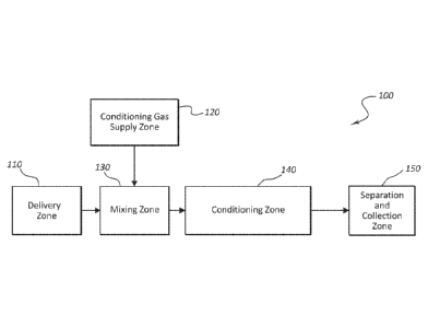
[0053] Figure 1 provides a schematic illustration of an embodiment of a
system for conditioning particulate crystalline material according to the
present
description. The system 100 includes a delivery zone 110, wherein one or
more crystalline materials (e.g., one or more pharmaceutically active agents
or
pharmaceutically acceptable excipients or adjuvants) may be delivered and
prepared for mixing with a conditioning gas. The system also includes a
conditioning gas supply zone 120. The conditioning gas is supplied from the
conditioning gas supply zone 120, and in certain embodiments, the conditioning
gas is generated within the conditioning gas supply zone 120. The crystalline
particulate material and the conditioning gas may be introduced into a mixing
zone 130, after which they enter a conditioning zone 140. The conditioning
zone 140 includes a controlled atmosphere contained and maintained within a
conditioning chamber. The controlled atmosphere includes the conditioning
gas and any delivery gas used for delivering the crystalline particulate
material,
and the particulate material being conditioned remains entrained, suspended,
or aerosolized within the controlled atmosphere within the conditioning
chamber. The crystalline material undergoes an annealing process within the
conditioning zone 140 as it is maintained within the conditioning zone 140 for
a
desired residence time. The micronized material may be separated from the
conditioning gas and collected from the conditioning zone 140 in the
separation
and collection zone 150, which can include any of a number of well-known
components suited to the collection of micronized material.
[0054] The nature of and extent to which annealing of the particulate
material takes place can be controlled by the residence time of the material
within the conditioning zone and by the properties of the conditioning gas,
including, for example the presence and concentration of one or more solvents,
and the temperature, flow rate, and direction or turbulence of flow of the
conditioning gas. In some embodiments of the systems disclosed herein, the
residence time of the micronized active agent particles in the conditioning
zone
13
CA 02905542 2015-09-10
WO 2014/144894 PCT/US2014/029489
140 may be controlled by the geometry of the conditioning zone 140 or by the
flow rate of the conditioning gas through the conditioning zone 140.
[0055] The material to be conditioned may be provided to the delivery
zone 110 in a form that is appropriate for the chosen material and the
conditioning process. Where a particulate material exhibiting a desired
particle
size distribution is desired, the material may be prepared to exhibit the
targeted
particle size distribution prior to introduction into the delivery zone 110.
In such
an embodiment, the particulate material can be fed from the delivery zone 110
into the mixing zone 130 using any suitable device or system for controlled
feeding of a powder or particulate material at a desired feed rate. Controlled
feeding of the particulate material will typically include entraining the
particulate
material in a dispersion component, such as, for example a delivery gas
suitable for dispersion and delivery of the particulate material into the
mixing
zone 130 and/or the conditioning zone 140.
[0056] In certain embodiments, particulate material may be subjected to
a micronization process within the delivery zone 110. In such embodiments,
the delivery zone 110 may include a device or system that processes the
crystalline material to provide a micronized particulate material that
exhibits a
desired particle size distribution. Where the delivery zone 110 includes a
device or system suitable for carrying out micronization of the selected
crystalline material, the delivery zone 110 may incorporate any one of a
number
of known devices or systems for micronization. For example, the crystalline
material may be micronized in the delivery zone 110 using known milling or
grinding processes, known crystallization or recrystallization processes, or
known micronization processes utilizing precipitation from supercritical or
near-
supercritical solvents, spray drying, spray freeze drying, or lyophilization.
[0057] In embodiments where the delivery zone 110 includes a
micronizer, the mixing zone 130 and/or conditioning zone 140 may be operably
linked to the micronizer. In such embodiments, the crystalline material may be
processed to exhibit the targeted particle size distribution within the
delivery
zone 110 and, prior to collection, immediately delivered to the mixing zone
130
14
CA 02905542 2015-09-10
WO 2014/144894 PCT/US2014/029489
while the particles remain airborne as they exit from the micronizer.
Therefore,
the systems and methods described herein allow for conditioning of micronized
material as a sequential but integrated step in a process of producing and
collecting a micronized crystalline material. Such "in-
line" or "in-process"
conditioning of micronized crystalline material provides the benefits
associated
with the annealing achieved by the conditioning process, while also
eliminating
the need to conduct a first process for producing micronized (or size
comminuted) material followed by a second, separate conditioning process for
annealing the micronized material.
[0058] The mixing
zone 130 illustrated in Figure 1 is shown as separate
from the conditioning zone 140. In such an embodiment, the crystalline
material to be conditioned (such as, e.g., micronized material suspended or
entrained within a delivery gas) and the conditioning gas are delivered to the
mixing zone 130 prior to their entry into the conditioning zone 140. The
mixing
zone 130 can be sized and configured as desired to achieve desired mixing of
the particulate material and conditioning gas. In certain embodiments, the
mixing zone 130 may include a dispersion head assembly into which both the
particulate material and the conditioning gas are fed and directed into the
conditioning zone 140. Alternatively, in other embodiments, the mixing zone
130 may be an area within the conditioning zone 140 where the particulate
material and the conditioning gas are delivered into the conditioning zone in
a
manner that accomplishes the mixing required for annealing of the particulate
material within the conditioning zone. In such embodiments, the micronized
material may be introduced into the conditioning zone as a particulate
material
entrained or aerosolized within a delivery gas, and the conditioning gas may
be
introduced into the conditioning chamber such that the conditioning gas begins
to mix with the delivery gas and the micronized material disbursed therein
upon
entry into the conditioning zone 140.
[0059] The
conditioning zone 140 may be formed within a conditioning
chamber, which can be provided by any structure, such as a column, tank,
tube, funnel, coil, or the like, suitable for maintaining a controlled
atmosphere
CA 02905542 2015-09-10
WO 2014/144894 PCT/US2014/029489
and receiving the particulate material and conditioning gas. The
characteristics
of the controlled atmosphere within the conditioning zone 140 can be adjusted
to achieve a desired conditioning of one or more selected particulate
materials.
In particular embodiments, the conditioning gas is delivered at a specified
rate
and mixes with the delivery gas at a selected ratio. For example, the
conditioning gas may be supplied to the conditioning zone 140 (e.g., through a
dispersion head assembly) at a targeted gas flow rate. The gas flow rate will
depend on, among other factors, the amount of micronized material being
processed and the angle at which the gas is introduced into the conditioning
zone 140. In certain embodiments, the conditioning gas is introduced into the
conditioning zone 140 at a rate ranging from about 20 SCFM up to about 500
SCFM, and the delivery gas having the particulate material to be conditioned
entrained therein may be supplied at a gas flow rate ranging from about 20
SCFM up to about 75 SCFM. However, depending on the angle at which the
conditioning and delivery gases are introduced into the conditioning zone 140
and the nature of the material being processed, the gas flow rate of both the
conditioning gas and the delivery gas may be increased as high as 3,300
SCFM. In other embodiments, the conditioning gas may be supplied at a flow
rate of 30 SCFM up to about 100 SCFM and the delivery gas containing the
micronized material to be conditioned may be supplied at a gas flow rate
ranging from about 30 SCFM up to about 60 SCFM. In addition to, or as an
alternative to, controlling the rate at which the conditioning gas is
introduced
into the controlled atmosphere, the ratio of the conditioning gas to the
delivery
gas may be selected to facilitate conditioning of the micronized material. In
particular embodiments, the conditioning gas is mixed with the delivery gas at
a
ratio selected from 1:1, 1.2:1, 1.4:1, 1.6:1, 1.8:1, 2.0:1, 2.2:1, 2.4:1,
2.6:1, 2.8:1,
3:1, 3.2:1, 3.4:1, 3.6:1, 3.8:1, and 4:1.
[0060] The temperature of the conditioning gas may also be controlled.
Annealing of particulate material can be significantly affected by
temperature.
In certain embodiments, the temperature of the conditioning gas is selected
from between about 10 C and 100 C. In specific examples of such
16
CA 02905542 2015-09-10
WO 2014/144894 PCT/US2014/029489
embodiments, the temperature of the conditioning gas may be selected from
one of the following ranges, between about 10 C and 70 C, between about
20 C and 50 C, between about 10 C and 50 C, and between about 20 C
and 30 C, depending on the nature of the particulate material being
processed.
[0061] The
conditioning gas may also include one or more solvent
vapors. In such embodiments, the conditioning gas includes a carrier gas
having one or more solvent vapors dispersed therein. The inclusion of a
solvent vapor within the conditioning gas can be particularly useful in
conditioning processes adapted to reduce or eliminate amorphous content and
to conditioning process adapted to reduce or eliminate the presence of
residual
solvent(s) by solvent exchange.
[0062] Where a
solvent is included in the conditioning gas, the solvent
will typically be selected according to the material to be conditioned. For
example, in embodiments where the material to be conditioned is water soluble,
the conditioning gas may include water vapor carried within an inert gas. In
certain embodiments, the solvent vapor may be a combination of water and
water miscible organic solvents (e.g., alcohols, ketones, esters, etc.)
Alternatively, in embodiments where the material to be conditioned is not
water
soluble, but exhibits solubility in one or more organic solvents, the solvent
vapor
included in the conditioning gas may simply include an organic solvent vapor,
such as an alcohol (e.g., ethanol, methanol, isopropyl alcohol, etc.), ketone
(e.g., acetone, methyl ketone, ethyl ketone, etc.), ester (e.g., ethyl
acetate,
etc.), aliphatic alcohol (e.g., octanol, etc.), or alkane (e.g., octane,
nonane, etc.)
vapor, carried within an inert gas. As used herein, "inert" refers to a
carrier gas
that is non-reactive with the micronized material being conditioned and
preferably the solvent vapor. Examples
of inert gases include, without
limitation, compressed dry air, nitrogen, inert gas (e.g., argon, helium,
etc.),
carbon dioxide, and the carrier gas included in the conditioning gas can be
selected according to the solvent vapor or combination of solvent vapors to be
used in the conditioning gas or conditioning zone. In embodiments where the
conditioning of the particulate material includes solvent exchange, the
17
CA 02905542 2015-09-10
WO 2014/144894 PCT/US2014/029489
solvent(s) included in the conditioning gas may be selected to provide
improved
safety and/or physiochemical stability of the particulate material.
[0063] Where a solvent is included in the conditioning gas, the
conditioning gas can be prepared and maintained at a specified temperature or
temperature range in order to maintain the solvent as a vapor. As already
mentioned, controlling the temperature of the conditioning gas can also serve
to
facilitate the conditioning process, with the temperature being selected to
facilitate a desired level of annealing over a selected residence time.
[0064] The
relative concentration of solvent vapor included in a
conditioning gas can also be adjusted to accomplish a desired level of
conditioning for different material characteristics. For
example, the
concentration of solvent vapor within the conditioning gas may be adjusted
based on the chemical or physical properties of the crystalline material to be
processed. In specific embodiments, the relative humidity (RH) or relative
saturation (RS) and temperature conditions of the conditioning gas are
selected
to provide RH or RS and temperature conditions that exceed the glass
transition temperature (Tg) of the amorphous content of the material being
processed. For example, for each of the solvents included within the
conditioning gas, the vapor pressure of the solvent may be maintained at a
vapor pressure of about 0.05 to 0.95 of the saturation vapor pressure for the
solvent.
[0065]
Crystallization of an amorphous phase typically occurs rapidly
when the amorphous material is exposed to conditions that exceed its glass
transition temperature, usually twenty degrees Celsius above the glass
transition temperature (Lechuga-Ballesteros, D.; Miller, D. P.; Zhang, J.,
Residual water in amorphous solids, measurement and effects on stability. In
Progress in Amorphous Food and Pharmaceutical Systems, Levine, H., Ed.
The Royal Society of Chemistry: London, 2002; pp 275-316). Exposure of
amorphous material to temperature in excess of the glass transition can be
achieved in the absence of any solvent by exposing the amorphous material to
a stream of hot air above its glass transition temperature. However, the glass
18
CA 02905542 2015-09-10
WO 2014/144894 PCT/US2014/029489
transition temperature is also a function of the fraction of solvent present
in the
amorphous material, an effect known as plasticization. Plasticization is
typically
represented by a plasticization curve, such as the one shown in Figure 16,
which shows the Tg of a given amorphous material as a function of solvent (in
this case water) content.
[0066] In addition, the solvent content held in an amorphous material is
a
function of the vapor concentration of the solvent surrounding the amorphous
solid. This can be illustrated by the sorption isotherm provided in Figure 17.
The sorption isotherm of a given material is a representation of the amount of
solvent in the amorphous material as a function of the solvent activity (which
is
proportional to the solvent vapor pressure to saturation solvent vapor
pressure
ratio) at a given temperature.
[0067] The glass transition plasticization curve and the sorption
isotherm
can be combined to construct a stability diagram as the one shown in Figure 18
for the selected material. The stability diagram shown in Figure 18 is one
created for glycopyrrolate. The stability diagram can be used to choose
operational conditions for the systems and methods described herein that
promote fast annealing of the crystalline material selected for conditioning.
For
example, as is illustrated in Figure 18, in the case of glycopyrrolate fast
crystallization of amorphous material will occur at RH>50 /0 in the range of
20-
40 C, and at 60 C it would only require 10"YoRH to promote annealing.
[0068] The nature and extent of annealing that takes place within the
conditioning zone can also be adjusted by altering the residence time of the
particulate material within the conditioning zone 140. The residence time is
the
average time particulate material spends within the conditioning zone 140. The
residence time of the particulate material within the conditioning zone 140
can
be adjusted by changes to one or more of a variety of process variables. For
example, the volume and dimensions of the conditioning chamber can be
altered, to provide longer or shorter residence times, with, for example,
relatively higher volume or larger physical dimensions generally resulting in
relatively longer residence times. The flow rates and temperatures of one or
19
CA 02905542 2015-09-10
WO 2014/144894 PCT/US2014/029489
both of the conditioning gas and the delivery gas can also be adjusted to
affect
residence time. In addition, the manner by which the conditioning gas or
delivery gas is introduced into the conditioning chamber can affect particle
residence time. As an example, introduction of the conditioning gas and/or
delivery gas in a manner that creates a generally linear flow through the
conditioning chamber may create a relatively shorter residence time compared
to introduction of the same gas(es) in a manner that creates a more turbulent
recirculating dispersion of the gas(es).
[0069] In
general, the residence time of the particulate material within the
conditioning chamber can be selected from about 0.5 seconds to several
minutes. In particular embodiments, the residence time may be up to about 10
minutes or 600 seconds. In particular embodiments, the residence time may be
selected from about 0.5 to about 10 seconds, 0.5 to about 20 seconds, 0.5 to
about 30 seconds, 0.5 to about 40 seconds, and 0.5 to about 50 seconds. In
certain such embodiments, the particulate material may be conditioned by the
conditioning gas for a residence time selected from about 0.5 seconds, 1
second, 1.5 seconds, 2 seconds, 2.5 seconds, 3 seconds, 3.5 seconds, 4
seconds, 5 seconds, 6 seconds, 7 seconds, 8 seconds, 9 seconds, and 10
seconds.
[0070] After the particulate material has been annealed in the
conditioning zone 140, the conditioned material is separated from the
conditioning gas and collected in the separation and collection zone 150. The
micronized material may be separated and collected from the conditioning gas
using known particle collection techniques and equipment. In certain
embodiments of the systems disclosed herein, the micronized material may
continue to anneal while in the separation and collection zone 150. The
collection zone 150 can be formed by or include a cyclone collector. Cyclone
collectors for collection of particulate materials, including micronized
materials,
and separation of such materials from a conditioning gas. Cyclone collectors
are commercially available and suitable for use as the collection zone 150 of
the systems described herein.
CA 02905542 2015-09-10
WO 2014/144894 PCT/US2014/029489
[0071] In
addition to a collection device, such as a cyclone collector, the
collection zone 150 may be configured to facilitate direct collection of the
processed material. Where a collection zone 150 is configured to allow direct
collection of the conditioned material, the collector included in the
collection
zone may simply deliver the conditioned product to a container from which the
conditioned material can be collected or removed. Such a container may
include a collection bag that can be removed from the collection device, as is
often used in conjunction with a cyclone collector. The collection bag may be
sealable and formed using a material that enables efficient collection of the
conditioned material, while also being permeable to a gas used in the
collection
system. In another embodiment, the collector included in the collection zone
150 may be configured as a holding chamber. In such an embodiment, the
collector, such as a cyclone collector, may be used to separate the
conditioned
material from a conditioning gas and collect the conditioned material into a
holding chamber where the conditioned material can be maintained in a
fluidized state for a desired period of time. Annealing of the crystalline
material
processed according to the present description is not always complete as the
material exits the conditioning zone 140, and may continue as the material is
collected. Depending on the material being processed and the annealing
conditions, it may be beneficial to maintain the conditioned material in a
fluidized state within a collection chamber for a period of time sufficient to
allow
additional progress of the annealing process.
[0072] In still
other embodiments, the collection zone 150 may be
configured to allow further processing of the conditioned material. In such
embodiments, the collection zone 150 may be operably linked to one or more
additional systems, including an additional conditioning system as described
herein, for further processing of the conditioned material. In such
embodiments, the collector included in the collection zone 150 may be
configured to deliver the conditioned material directly for continued
processing
or the collection zone 150 may be configured to include or be in operable
communication with a holding chamber as described and illustrated herein,
21
CA 02905542 2015-09-10
WO 2014/144894 PCT/US2014/029489
such as, for example, in association with the systems illustrated in Figure 19
and Figure 20.
[0073] In some
embodiments, the systems and methods described
herein may be utilized to simultaneously process and condition more than one
particulate material. For example, two or more micronized materials may be
simultaneously introduced into a conditioning zone. The materials may be
combined prior to introduction into the conditioning zone or they may be
introduced independently into the conditioning zone. In some embodiments,
the materials may be combined prior to micronization and introduced into the
conditioning zone as a particulate material including a combination of two or
more chemical entities. Even further, where two or more different particulate
materials are introduced into the conditioning zone (whether as a combined
product stream or as two or more independently introduced materials), the
materials may exhibit similar solubility characteristics (e.g., each of the
different
materials exhibit solubility in water or each of the materials exhibit
solubility in a
given organic solvent). However, the methods described herein are also suited
to simultaneously conditioning two or more materials in the same conditioning
zone where at least two of the two or more different materials exhibit
different
solubility characteristics (e.g., at least one is water soluble, while another
is
soluble only in an organic solvent, or one is soluble in a first organic
solvent,
while a second is soluble in a second organic solvent).
[0074] Certain
embodiments of a system for the in-process conditioning
of a micronized material according to the present description can be
represented by the system illustrated in Figure 2. Because the delivery zone
of
the system illustrated in Figure 2 includes a device configured for the
micronization of the material to be conditioned, the delivery zone of the
system
will be referred to as a micronizing zone 210. As shown in Figure 2, the
micronizing zone 210 may be configured to deliver aerosolized micronized
particles directly into a mixing zone 230. In
specific embodiments, the
micronization zone 210 includes a jet mill 213 and the crystalline material
211
to be micronized is delivered to the jet mill 213 using a standard feeder 212.
22
CA 02905542 2015-09-10
WO 2014/144894 PCT/US2014/029489
After micronization, the micronized material 235 may be delivered through an
outlet 214 as aerosolized particles carried by a delivery gas 216 and supplied
to
the mixing zone 230.
[0075] The
micronized crystalline material is supplied to the mixing zone
230 as a micronized material with a desired particle size distribution. In
certain
embodiments, for example, at least 90% of the micronized particles by volume
exhibit an optical diameter of about 10 pm or less. In other embodiments, at
least 90% of the micronized crystalline particles by volume exhibit an optical
diameter selected from a range of about 10 pm to about 1 pm, about 9 pm to
about 1 pm, about 8 pm to about 1 pm, about 7 pm to about 1 pm, about 5 pm
to about 2 pm, and about 3 pm to about 2 pm. In further embodiments, at least
90% of the micronized crystalline particles by volume exhibit an optical
diameter selected from 10 pm or less, 9 pm or less, 8 pm or less, 7 pm or
less,
6 pm or less, 5 pm or less, 4 pm or less, 3 pm or less, 2 pm or less, or 1 pm
or
less.
[0076] The
micronizing zone 210 may be separated from an external
environment or contained within a safety barrier or enclosure (not shown).
Such a design can be particularly advantageous where the micronized material
is an active agent or is otherwise biologically active. The safety barrier may
be
used in order to prevent unwanted contact with any micronized material
produced in the micronizing zone 210. Where included in the systems
described herein, a safety barrier may be constructed of any suitable material
such as metal, glass, plastic, composites, etc., that are sufficient to
contain
micronized particles.
[0077] With
reference to Figure 2, in particular embodiments, the
conditioning gas 226 utilized in an in-line conditioning system may be
prepared
within the conditioning gas supply zone 220. For example, the conditioning gas
supply zone 220 may include a heating chamber 221 to which a carrier gas 222
may be provided for heating to a desired temperature. In one
such
embodiment, the heating chamber 221 comprises a heat source, such as an
electric heater or furnace, for heating the carrier gas 222. The carrier gas
222
23
CA 02905542 2015-09-10
WO 2014/144894 PCT/US2014/029489
provided for use in the systems disclosed herein may comprise one or more
gases suitable for the methods described herein for conditioning a given
micronized crystalline material. For example, the carrier gas 222 may comprise
one or more inert gasses or atmospheric gasses such as those described
herein, including, for example, compressed air, nitrogen, oxygen, and helium.
[0078] The
conditioning gas supply zone 220 may further comprise a
liquid evaporation chamber 225. The solvent used to produce the solvent vapor
disbursed within the carrier gas 222 can be generated within or provided from
the evaporation chamber 225, and the evaporation chamber can be configured
to provide the carrier gas 222 with a desired concentration of solvent vapor
within the conditioning gas 226. Where the micronized crystalline material is
water soluble, the solvent can be an aqueous solvent, such as purified or
distilled water, and in such embodiments, the evaporation chamber 225 is
configured to create a conditioning gas 226 having a desired relative
humidity.
In other embodiments, particularly where the micronized crystalline material
to
be conditioned is not water soluble, the solvent for use with the systems
disclosed herein may be a non-aqueous liquid, such as an organic solvent
described herein.
[0079] A liquid
atomizer 223 may be used to deliver liquid solvent to the
carrier gas 222 in the form of atomized liquid droplets 224 suspended within
the
carrier gas 222. Atomization of the liquid solvent facilitates conversion of
the
liquid solvent into a solvent vapor within the evaporation chamber 225. In
more
specific embodiments, a liquid atomizer used in the systems described herein
provides control over the size of the atomized droplets delivered to the
carrier
gas 222 as well as the rate and volume of liquid solvent atomized. Where
used, a liquid atomizer 223 can be selected from, for example, pressure
nozzles, pneumatic atomizers, impinging jet atomizers. In one
such
embodiment, the carrier gas 222 is heated in the heating chamber 221, a liquid
atomizer 223 delivers liquid solvent to the carrier gas within the
conditioning
gas supply zone 220, and the carrier gas 222 and atomized liquid solvent 224
are supplied to the liquid evaporation chamber 225. As the carrier gas 222 and
24
CA 02905542 2015-09-10
WO 2014/144894 PCT/US2014/029489
atomized liquid solvent 224 pass through the liquid evaporation chamber, the
liquid solvent vaporizes and the carrier gas becomes a conditioning gas 226
having a desired solvent vapor concentration.
[0080] In certain embodiments, where the solvent vapor is formed from
an aqueous solvent, the conditioning gas 226 may be supplied at a temperature
ranging from about 20 C to about 100 C, and with a relative humidity ranging
from about 0.05% to about 75%. In more specific embodiments where the
solvent used to form the solvent vapor is an aqueous solvent, the conditioning
gas 226 may be supplied having a temperature selected from at least about 20
C, 21 C, 22 C, 23 C, 24 C, 25 C, 26 C, 27 C, 28 C, 29 C, and 30 C
and having a relative humidity selected from at least about 50%, 51%, 52%,
53%, 54%, 55%, 56%, 57%, 58%, 59%, 60%, 61%, 62%, 63%, 64%, 65%,
66%, 67%, 68%, 69%, 70%, 71%, 72%, 73%, 74% and 75%. In particular
embodiments, however, the temperature may be as high as 22 C and the
relative humidity as low as 0.05%.
[0081] With continued reference to Figure 2, the mixing zone 230 is
configured to mix incoming micronized crystalline material 235 with the
conditioning gas 226. In particular embodiments, the mixing zone 230 is
configured to mix a delivery gas flow 216 with a conditioning gas 226. In some
embodiments of the systems disclosed herein for in-process conditioning of
micronized active agents, the mixing zone 230 may comprise a dispersion head
assembly configured to mix the delivery gas 216 with the conditioning gas 226.
With reference to Figures 3A, 3B, and 3C, a dispersion head assembly 330
suitable for use in the systems described herein may include a housing 335 and
a mixing head 340, wherein a conditioning gas 326 and a delivery gas 316 may
be mixed. The housing 335 comprises a conditioning gas inlet 324 and a gas
outlet 325, wherein the conditioning gas 326 may be supplied to the dispersion
head assembly 330 through the conditioning gas inlet 324. As shown in Figure
30, the conditioning gas 326 may be delivered to the mixing head 340 where it
can enter an injection nozzle 345 through an injection inlet 342. The mixing
head 340 may also comprise a delivery gas inlet 350 through which the delivery
CA 02905542 2015-09-10
WO 2014/144894 PCT/US2014/029489
gas 316, having the micronized material entrained therein, may enter the
injection nozzle 345. As the delivery gas 316 and the conditioning gas 326
enter the injection nozzle 345 they are mixed together thereby exposing the
micronized crystalline material to the conditioning gas 326.
[0082] Where a mixing head is included in a system according to the
present description, as shown in Figure 3, the mixing head may be modifiable
and interchangeable such that the mixing head 340 may be removed from the
dispersion head assembly 330 and modified or exchanged for a different mixing
head. The design of the mixing head 340, such as the size, shape, number,
and location of one or more injection nozzle inlets 342, may be modified and
adjusted to control the mixing dynamics, volume, and/or rate at which the
delivery gas and conditioning gas exit the mixing head 340 and are delivered
to
the conditioning zone 240. In specific embodiments, the design of the mixing
head 340, including the size, shape, and location of the delivery gas inlet
350,
may be modified and adjusted to control the mixing dynamics and the volume
and/or rate of mixed gases that exit the mixing head 340.
[0083] In certain embodiments, the dispersion head assembly and/or
mixing head may be configured to mix the conditioning gas and the micronized
crystalline material upon entry into the conditioning zone 240. Alternatively,
the
dispersion head assembly and/or mixing head may be configured to mix the
conditioning gas and micronized crystalline material before the mixture leaves
the mixing zone 230 and is delivered to the conditioning zone 240. For
example, Figures 4A and 4B provide further embodiments of different mixing
heads that may be used in the systems described herein. Figure 4A shows
mixing head 420 comprising delivery gas inlet 450 and injection nozzle inlet
425
located near the base of the injection nozzle 445. Figure 4B shows a mixing
head 430 comprising a delivery gas inlet 450 and injection nozzle inlet 435
located near the edge of the injection nozzle 445. In further embodiments, the
mixing heads disclosed herein may include one or more injection nozzle inlets
located at desired positions within or around the injection nozzle 445. In
other
embodiments, the conditioning gas and the micronized crystalline material may
26
CA 02905542 2015-09-10
WO 2014/144894 PCT/US2014/029489
be mixed in the injection nozzle 445 before the mixture leaves the mixing zone
230 and is delivered to the conditioning zone 240.
[0084] The systems disclosed herein can include a mixing zone 230
configured to mix the conditioning gas 226 with the delivery gas 216 in a
desired ratio, such as a ratio of gas volumes (volume/volume) or a mass flow
rate ratio (SCFM/SCFM). For example, in particular embodiments, the mixing
zone, including, for example, a dispersion head assembly, may be configured to
mix the conditioning gas 226 and delivery gas 216 in a ratio of about 1 to 4
parts conditioning gas 226 with about 1 part of the delivery gas 216. In
certain
such embodiments, the conditioning gas 226 may be mixed with the delivery
gas 216 in a ratio selected from any of about 1:1, 1.2:1, 1.4:1, 1.6:1, 1.8:1,
2.0:1, 2.2:1, 2.4:1, 2.6:1, 2.8:1, 3:1, 3.2:1, 3.4:1, 3.6:1, 3.8:1, and 4:1.
[0085] With continued reference to Figure 2, the conditioning zone 240
(also referred to herein as a "conditioning chamber") included in the systems
described herein is configured to contain and maintain a controlled atmosphere
tailored to the conditioning of a desired micronized material and to receive
the
delivery gas 216 and conditioning gas 226 from the mixing zone 230. As noted
above, in some embodiments, the conditioning chamber 240 and mixing zone
230 may be provided as separate subsystems placed in fluid communication
one with another. Alternatively, the mixing zone 230 and conditioning chamber
240 may be integrated such that two different subsystems are not required.
Where, provided as separate subsystems, the mixing zone 230 and
conditioning chamber 240 are configured such that the mixed delivery gas 216
and conditioning gas 226 are delivered into the conditioning chamber 240 from
the mixing zone 230.
[0086] In certain embodiments, after the conditioning gas 226 and the
delivery gas 216, comprising micronized active agent particles, are mixed
together in the mixing zone 230, the micronized particles 235 enter the
conditioning chamber 240 together with the conditioning gas 226. While in the
conditioning chamber 240, the micronized particles 235 are exposed for a
desired time period to the conditioning gas 226, and during their residence
time
27
CA 02905542 2015-09-10
WO 2014/144894 PCT/US2014/029489
within the conditioning chamber 240, the amorphous material included in the
micronized particles 235 anneals. The residence time of the micronized
particles 235 in the conditioning chamber 240 may be controlled by one or more
of the following: the dimension and geometry of the conditioning chamber 240;
the rate at which the mixture of the conditioning gas 226 and the delivery gas
216 are delivered into the conditioning chamber 240; the flow pattern of the
mixture of the conditioning gas 226 and the delivery gas 216 within the
conditioning chamber 240; the amount of micronized material carried by the
mixture of delivery gas 216 and conditioning gas 226; and the system used for
collection of the conditioned micronized material. In particular embodiments,
the residence time of the micronized active agent particles 235 within the
conditioning chamber 240 may be for a period of time ranging from about 0.5 to
seconds. In certain
such embodiments, the residence time of the
micronized particles 235 within the conditioning chamber 240 may be selected
from one the residence times detailed herein.
[0087] A
conditioning chamber 240 suitable for use in the systems
described may be configured as for example, a tank, a column, a funnel, a
tube,
or other appropriate devices or structures. In further
embodiments, the
conditioning chamber 240 may further include heaters, inlets, outlets, and
other
means and devices for controlling the conditions and gas flow within the
conditioning chamber 240. The geometry of the conditioning chamber 240 may
be modified by adjusting, for example, the length, width, height, volume, and
shape of the conditioning chamber 240.
[0088]
Conditioned micronized active agent particles 246 are separated
from the conditioning gas 226 in a separating zone 250. The separating zone
250 may comprise elements or devices designed to separate conditioned
micronized active agent particles 246 from the carrier gas 216 and
conditioning
gas 226, such as, for example, a cyclone separator, bag collector or other
separation equipment, as known by those of skill in the art. In particular
embodiments, the separating zone 250 may comprise an exhaust outlet 255
whereby, for example, the exhaust gas and other materials may exit from the
28
CA 02905542 2015-09-10
WO 2014/144894 PCT/US2014/029489
separating zone 250. Though micronized material will have been conditioned
within the conditioning zone 240, in certain embodiments, the process of
annealing is does not end immediately upon collection of the micronized
material from the conditioning zone 240. For example, in certain embodiments,
although the controlled atmosphere of the conditioning zone 240 initiates or
even substantially completes the annealing process, annealing of amorphous
material continues as the micronized material exits the conditioning zone 240
and is separated and collected. In addition to a system or device of
separating
the conditioned micronized material from the delivery and conditioning gases,
the separating zone 250 may further included one or more filters and
collectors.
Filters may be placed, for example, at the exhaust outlet 255 to capture or
prevent unwanted escape of fines. Additionally, a collector 260 is included
within the separating zone 250 to facilitate capture and containment of the
conditioned material. Once collected the, conditioned crystalline material can
be stored or further processed, as desired.
[0089] Though Figure 1 and Figure 2 illustrate conditioning systems
having a single conditioning zone, systems according to the present
description
may also include multiple conditioning zones. In such embodiments, the
different conditioning zones may expose the crystalline particulate material
to
different annealing conditions. Such systems, therefore, can be configured to
provide multiple in-process conditioning steps. Figure 19 and Figure 20
provide
schematic illustrations of two embodiments of conditioning systems that
provide
two conditioning zones, thereby facilitating multiple annealing steps within a
single system.
[0090] As shown in Figure 19, a conditioning system 600 as described
herein may include a delivery zone 610, a conditioning gas supply zone 620, a
mixing zone 630, a conditioning zone 640, and a collection zone 650, as
described herein. In addition, the system may include a product holding
chamber 660 that is separated from the collection zone 650 by, for example, a
cut-off valve 670. In such an embodiment, the conditioning system can be
configured as described in relation to the systems illustrated in Figure 1 and
29
CA 02905542 2015-09-10
WO 2014/144894 PCT/US2014/029489
Figure 2, and the system can be adapted for annealing a wide range of
materials using any suitable process conditions described herein. As
conditioned product is collected in the collection zone 650, the cut-off valve
670
remains open and conditioned product is delivered to the product holding
chamber 660. The product holding chamber 660 can be configured to maintain
the conditioning product in a continuously fluidized state. The cut-off valve
670
can be any valve mechanism suited to use in this context, that can be cycled
between open and closed states, and when closed provides a physical barrier
capable of separating the conditioned material from collection zone 650. In
certain embodiments, the cut-off valve 670 seals the product holding chamber
660 from the collection zone 650 such that, once closed, the conditioned
product will not regress into the collection zone 650 and process gases (e.g.,
delivery gas or conditioning gas) do not pass between the collection zone 650
and the product holding chamber 660.
[0091] Once delivered to the product holding chamber 660, the
conditioned product may be maintained in a fluidized state and the cut-off
valve
670 closed. At that point, the system can re-equilibrate to supply a secondary
conditioning gas. In such an embodiment, the upstream components of the
conditioning system 600 (e.g., the delivery zone 610, conditioning gas supply
zone 620, mixing zone 630, conditioning zone 640, and collection zone 650)
may be purged of the primary conditioning gas used to condition the material
present in the product holding chamber 660, and a secondary conditioning gas
can be supplied from and/or generated in the gas supply zone 620. Once the
system is re-equilibrated with the secondary conditioning gas, the cut-off
valve
670 may be opened to expose the conditioned product contained within the
product holding chamber 660 to the secondary conditioning gas. The product
can be maintained in a continuously fluidized state within the product holding
chamber 660 as it is exposed to the secondary conditioning gas for a period of
time sufficient to accomplish a secondary annealing. The nature and content of
the secondary conditioning gas, including the presence and concentration of
one or more solvents, and the temperature, flow rate, and direction or
CA 02905542 2015-09-10
WO 2014/144894 PCT/US2014/029489
turbulence of flow of the secondary conditioning gas may be adjusted to
accomplish a desired secondary annealing for a wide range of selected
materials using process conditions described herein. By
adjusting the
characteristics of the secondary conditioning gas and the residence time of
the
particulate material within the product holding chamber 660, the system
illustrated in Figure 19 can be utilized to provide multiple conditioning
steps
using a single system.
[0092] The
residence time of the conditioned product within the holding
chamber 660 can be easily adjusted based on the material itself, the
conditioning gas(es), and the nature or extent of annealing desired. For
example, as is true of particles conditioned within a conditioning zone, the
residence time of a conditioned product within a holding chamber 660 may be a
matter of seconds or minutes. For example the residence time of the
conditioned material within the holding chamber 660 may be selected from
those residence times detailed above in relation to the conditioning zone.
However, the conditioned product can also be maintained within the holding
chamber 660 indefinitely. In certain embodiments, the conditioned product is
maintained within a holding chamber 660 for a time selected from up to 5
minutes, up to 10 minutes, up to 30 minutes, up to 1 hour, up to 1.5 hours, up
to
2 hours, up to 5 hours, up to 10 hours, up to 12 hours, up to 18 hours, and up
to
24 hours. Such flexibility enables the conditioned product to be exposed to a
secondary conditioning gas for any amount of time needed to accomplish
secondary conditioning. A relatively longer residence time affords exposure to
a secondary conditioning gas over a long period of time and may be
particularly
useful for a secondary conditioning process that requires more time than might
be practically achieved within a given system's conditioning zone.
[0093] Figure 20
illustrates a conditioning system 700 that includes two
conditioning subsystems, a primary conditioning system 701 and secondary
conditioning system 801. The primary conditioning system 701, includes a
delivery zone 710, a primary conditioning gas supply zone 720, a primary
mixing zone 730, a primary conditioning zone 740, and a primary collection
31
CA 02905542 2015-09-10
WO 2014/144894 PCT/US2014/029489
zone 750. The primary conditioning system 701 and the secondary
conditioning system 801 may be separated by, for example, a primary holding
chamber 760 and one or more cut-off valve 770 (only a single cut-off valve is
shown). The primary holding chamber 760 may be configured for maintaining
conditioned product received from the primary conditioning system 701 in a
continuously fluidized state, and the cut-off valve 770 can be any valve
mechanism suited to use in this context, that can be cycled between open and
closed states, and when closed provides a physical barrier capable of
isolating
the primary and secondary conditioning systems 701, 801. In certain
embodiments, the cut-off valve 770 seals the primary holding chamber 760
from the secondary conditioning system 801 such that, when closed, product
collected from the primary conditioning system 701 will not pass into the
secondary conditioning system 801, material transferred to the secondary
conditioning system 801 will not regress into the primary conditioning system
701, and process gases (e.g., delivery gas or conditioning gas) do not pass
between the primary and secondary conditioning systems 701, 801. In some
embodiments, a second cut-off valve (not shown) can be positioned between
the primary holding chamber 760 and the primary collection zone 750. Such a
configuration may be particularly advantageous where communication of
process gases between the primary and secondary conditioning systems 701,
801 must be minimized.
[0094] As shown
in Figure 20, the secondary conditioning system 801
may include a secondary conditioning gas supply zone 820, a secondary mixing
zone 830, a secondary conditioning zone 840, and a secondary collection zone
850. In the embodiment illustrated in Figure 20, the primary and secondary
conditioning systems 701, 801 can be configured as described in relation to
the
systems illustrated in Figure 1 and Figure 2, and the systems can be adapted
for conditioning a wide range of materials using any process conditions
described herein.
[0095] As
material is processed in the primary conditioning system 701 a
primary annealing of the material takes place and the primary annealed
32
CA 02905542 2015-09-10
WO 2014/144894 PCT/US2014/029489
material is collected in the primary collection zone 750 and delivered to the
primary holding chamber 760. While the product is processed in the primary
conditioning system 701 and collected in the primary holding chamber 760, the
cut-off valve 770 will typically remain closed. Once the first conditioning
process is complete and the primary annealed material is collected in the
primary holding chamber 760, the cut-off valve 770 may be opened and the
primary annealed material delivered into the secondary mixing zone 830. The
primary annealed material may be dispersed within a delivery gas as it is
delivered to or within the secondary mixing zone 830. The delivery gas can be
any suitable delivery gas as described herein, and by dispersing the primary
annealed product in a delivery gas, the primary annealed product is suspended
or entrained within the delivery gas. A secondary conditioning gas is
delivered
and/or generated within the secondary conditioning gas supply zone 820, and
the secondary conditioning gas is mixed with the primary annealed product
(and any delivery gas used to disperse the primary annealed product) in the
secondary mixing zone 830.
[0096] The primary annealed product remains entrained, suspended or
aerosolized in the secondary conditioning gas within the secondary
conditioning
zone 840. The primary annealed product is maintained within the secondary
conditioning zone 840 for a period of time sufficient to accomplish a
secondary
annealing. As is true of the conditioning gas utilized in each embodiment of
the
systems described herein, the nature and content of the secondary conditioning
gas, including the presence and concentration of one or more solvents, and the
temperature, flow rate, and direction or turbulence of flow of the secondary
conditioning gas may be adjusted to accomplish a desired secondary annealing
for a wide range of selected materials using process conditions described
herein. By adjusting the characteristics of the secondary conditioning gas and
the residence time of the particulate material within the secondary
conditioning
zone 840, the system illustrated in Figure 20 can be utilized to provide
multiple
conditioning steps using a single system.
33
CA 02905542 2015-09-10
WO 2014/144894 PCT/US2014/029489
[0097] Though
described in relation to embodiments illustrated in the
figures provided herein, conditioning systems according to the present
description are not limited to the specific, illustrated embodiments. The
systems for conditioning crystalline particulate materials described herein
are
scalable and adaptable for areas of various size. In particular embodiments,
the systems disclosed herein may be scaled-up or scaled-down with regard to,
for example, gas flow rates, active agent mass, material output, desired
particle
residence time, etc., according the desired output rate and the available
space
and equipment. In certain embodiments, the systems disclosed herein may be
assembled as a modular unit and incorporated or built into established
processes and systems for the manufacture of conditioned particulate material,
and are well-suited for efficient production of conditioned, micronized
particulates. For example, the systems as disclosed here may be incorporated
into commercial milling and micronization processes or a built into a spray
drying system. In further embodiments, the systems described herein may be
operated as part of a batch process where one or more micronized materials
are conditioned and then collected in separate batches. In
alternative
embodiments, the systems described herein may be operated as part of a
continuous feed process whereby one or more micronized materials are
continuously delivered to the system and continuously conditioned and
collected.
III. Methods for conditioning particulate crystalline material
[0098] Methods
for conditioning particulate crystalline material are also
provided herein. Methods according to the present description can be carried
out using the conditioning systems provided herein. In general, the methods
described herein include: (1)
generating and/or providing a crystalline
particulate material; (2) introducing the particulate material in an
atmosphere
where it is blended with a conditioning gas; (3) maintaining the particulate
material in contact with the conditioning gas for a desired residence time;
and
(4) collecting the conditioned particulate material. In specific embodiments,
the
34
CA 02905542 2015-09-10
WO 2014/144894 PCT/US2014/029489
particulate material is a micronized crystalline material. Examples of
materials
that may be conditioned using the methods described herein include those
materials already described. In particular embodiments of methods according
to the present description, the material to be conditioned is typically
entrained
or aerosolized within a delivery gas that is blended with the conditioning
gas,
and the particulate material remains entrained, suspended or aerosolized in
the
conditioning gas as it travels through the conditioning zone. The nature of
the
conditioning gas and the residence time of the particulate material within the
conditioning zone are controlled to accomplish annealing of the material.
[0099] In
specific embodiments, the methods include a continuous
process for micronizing, conditioning, and collecting a crystalline material.
In
such embodiments, generating the crystalline material includes subjecting the
material to a micronization process and conditioning of the micronized
material
may be conducted in-line with particle collection. Where, the
methods
described herein provide in-line or in-process conditioning of micronized
material (or, more generally, any size comminuted material), the particulate
material may be blended with a conditioning gas and retained within a
conditioning zone to anneal the particulate prior to particle collection.
[0100] In other
embodiments, methods according to the present
description include primary and secondary conditioning steps. In such
embodiments, the crystalline particulate material can be introduced into
(e.g.,
entrained, suspended, or aerosolized within) a first conditioning gas to carry
out
a primary annealing and subsequently introduced into (e.g., entrained,
suspended, or aerosolized within)a second conditioning gas to carry out a
secondary annealing. Alternatively, for certain materials, a conditioning gas
may be selected that provides substantially simultaneous primary and
secondary annealing of the particulate material. For example, in methods where
primary and secondary annealing are carried out using a single conditioning
gas, the conditioning gas may anneal the particulate material through both
reduction of amorphous content and removal of an undesired residual solvent
by vaporization or solvent replacement.
84013607
[0101] The
methods provided can be tailored to specific materials to be
processed. For example, glycopyrronium is an active agent that can be
conditioning using the systems and methods described herein. Micronization of
crystalline glycopyrronium can lead to a micronized material that includes
significant amorphous content, and in particular embodiments, the present
methods can be adapted to reduce or eliminate amorphous material from
crystalline glycopyrronium particulates. Glycopyrronium conditioned according
to the present description may be in any crystalline form, isomeric form or
mixture of isomeric forms. In this regard, the form of glycopyrronium may be
selected to optimize the activity and/or stability of glycopyrronium. Where
appropriate, glycopyrronium may be provided as a salt (e.g. alkali metal or
amine salts, or as acid addition salts), esters or solvate (hydrates).
Suitable
counter ions include, for example, fluoride, chloride, bromide, iodide,
nitrate,
sulfate, phosphate, formate, acetate, trifluoroacetate, propionate, butyrate,
lactate, citrate, tartrate, nnalate, maleate, succinate, benzoate, p-
chlorobenzoate, diphenyl-acetate or triphenyl acetate, o-hydroxybenzoate, p-
hydroxybenzoate, 1-hydroxynaphthalene-2-carboxylate, 3-hydroxynaphthalene-
2-carboxylate, methanesulfonate and benzenesulfonate. In
particular
embodiments of the methods described herein, the bromide salt of
glycopyrronium is used, namely (34(cyclopentylhydroxyphenylacetypoxy]-1, 1-
dimethyl-, bromide). The bromide salt of glycopyrronium is commonly referred
to as glycopyrrolate. Glycopyrrolate is commercially available and can be
prepared according to the procedures set out in U.S. Pat. No. 2,956,062.
[0102] Where crystalline glycopyrronium, such as crystalline
glycopyrrolate, is the material processed by the methods described herein, the
glycopyrronium material can be micronized to exhibit particle size
characteristics as described herein, such as, for example, a particle size
distribution suitable for pulmonary delivery.
Moreover, the micronized
glycopyrronium can be prepared and provided using any suitable micronization
technique and delivered into the conditioning chamber via a delivery gas
36
Date Recue/Date Received 2020-10-07
CA 02905542 2015-09-10
WO 2014/144894 PCT/US2014/029489
suitable to the chosen micronization technique. In one such embodiment, the
glycopyrronium is micronized via a jet mill and the delivery gas may be
typical
gas flow exiting the jet mill, which would include aerosolized, micronized
particles of glycopyrronium.
[0103] In
specific embodiments, the bromide salt of glycopyrronium
(glycopyrrolate) may be processed according to the present methods. Where
glycopyrrolate is the material being conditioned, a conditioning gas may be
mixed with a delivery gas (e.g., a jet mill gas flow) in a ratio of about 1 to
4 parts
conditioning gas flow with about 1 part of the delivery gas. In certain such
embodiments, the conditioning gas flow may be mixed with the jet mill gas flow
in a ratio selected from about 1:1, 1.2:1, 1.4:1, 1.6:1, 1.8:1, 2.0:1, 2.2:1,
2.4:1,
2.6:1, 2.8:1, 3:1, 3.2:1, 3.4:1, 3.6:1, 3.8:1, and 4:1. In specific
embodiments,
the conditioning gas may be supplied at a gas flow rate ranging from about 150
SCFM up to about 500 SCFM, and the delivery gas may be supplied at a gas
flow rate of ranging from about 20 SCFM up to about 75 SCFM. However, in
some embodiments, depending on the desired conditions for the conditioning
zone and the nature of the material being processed, the gas flow rate of both
the conditioning gas and the delivery gas may be increased as high as 3,300
SCFM.
[0104] When
conditioning glycopyrrolate, the conditioning gas may be
delivered at a temperature ranging from about 20 C to about 30 C and include
water vapor as a solvent. In
particular embodiments of methods for
conditioning glycopyrrolate, the temperature of the conditioning gas may be
selected from at least 20 C, 21 C, 22 C, 23 C, 24 00, 25 C, 26 00, 27 C,
28 C, 29 C, and 30 C. Moreover, where included in the conditioning gas for
annealing glycopyrrolate according to the methods described herein, water
vapor may be provided at a concentration that results in a relative humidity
ranging from about 50% to about 80%. In particular embodiments of methods
for conditioning glycopyrrolate, the conditioning gas may be supplied at a
temperature described herein with a relative humidity selected from at least
about 50%, 51%, 52%, 53%, 54%, 55%, 56%, 57%, 58%, 59%, 60%, 61%,
37
84013607
62%, 63%, 64%, 65%, 66%, 67%, 68%, 69%, 70%, 71%, 72%, 73%, 74% and
75%. At the temperatures and relative humidity described herein, the residence
time of the micronized glycopyrrolate material within the conditioning chamber
may be from about 0.5 to about 10 seconds. In certain such embodiments, the
micronized glycopyrrolate material is present within the conditioning chamber
for a residence time selected from about 0.5 seconds, about 1 second, about
1.5 seconds, about 2 seconds, about 2.5 seconds, about 3 seconds, about
3.5 seconds, about 4 seconds, about 5 seconds, about 6 seconds, about 7
seconds, about 8 seconds, about 9 seconds, and about 10 seconds.
However, the residence time can be adjusted as needed to achieve the desired
reduction of amorphous content.
[0105] In other embodiments, the methods provided can be tailored to
for
the annealing of materials soluble in organic solvents. For example, the
methods described herein can be tailored to the conditioning of corticosteroid
active agents soluble in organic solvents. In certain such embodiments, the
methods described herein can be tailored for the conditioning of a
corticosteroid
selected from fluticasone and budesonide. Fluticasone, pharmaceutically
acceptable salts of fluticasone, such as fluticasone propionate, and
preparation
of such materials are known, and described, for example, in U.S. Patent
Nos. 4,335, 21,14,187,301, and U.S. Patent Publication No. U52008/125407.
Budesonide is also well known and described, for example, in U.S. Patent
No. 3,929,768.
[0106] Micronization of crystalline corticosteroids, such as
budesonide
and fluticasone, can lead to a micronized material that includes significant
amorphous content, and in particular embodiments, the present methods can
be adapted to reduce or eliminate amorphous material from particulate
crystalline corticosteroid material. A corticosteroid conditioned according to
the
present description may be in any crystalline form, isomeric form or mixture
of
isomeric forms. In this regard, the form of the corticosteroid may be selected
to
optimize the activity and/or stability of corticosteroid. Where appropriate,
the
38
Date Recue/Date Received 2020-10-07
CA 02905542 2015-09-10
WO 2014/144894 PCT/US2014/029489
corticosteroid may be provided as a salt (e.g. alkali metal or amine salts, or
as
acid addition salts), esters or solvate (hydrates).
[0107] Where a
crystalline corticosteroid material, such as crystalline
fluticasone or budesonide, is the material processed by the methods described
herein, the corticosteroid material can be micronized to exhibit particle size
characteristics as described herein, such as a particle size distribution
suitable
for pulmonary delivery. Moreover,
the micronized corticosteroid can be
prepared and provided using any suitable micronization technique and
delivered into the conditioning chamber via a delivery gas suitable to the
chosen micronization technique. In one such embodiment, the selected
corticosteroid is micronized via a jet mill and the delivery gas may be
typical
gas flow exiting the jet mill, which would include aerosolized, micronized
particles of the corticosteroid.
[0108] In
specific embodiments, the corticosteroid to be processed
according to the present methods is selected from fluticasone propionate and
budesonide. In such embodiments, a conditioning gas may be mixed with a
delivery gas (e.g., a jet mill gas flow) in a ratio of about 1 to 4 parts
conditioning
gas flow with about 1 part of the delivery gas. In certain such embodiments,
the
conditioning gas flow may be mixed with the jet mill gas flow in a ratio
selected
from about 1:1, 1.2:1, 1.4:1, 1.6:1, 1.8:1, 2.0:1, 2.2:1, 2.4:1, 2.6:1, 2.8:1,
3:1,
3.2:1, 3.4:1, 3.6:1, 3.8:1, and 4:1. In specific embodiments, the conditioning
gas may be supplied at a gas flow rate ranging from about 150 SCFM up to
about 500 SCFM and the delivery gas may be supplied at a gas flow rate of
ranging from about 20 SCFM up to about 75 SCFM. However, in some
embodiments, depending on the desired conditions for the conditioning zone
and the nature of the material being processed, the gas flow rate of both the
conditioning gas and the delivery gas may be increased as high as 3,300
SCFM.
[0109] When
conditioning a corticosteroid exhibiting solubility in an
organic solvent, such as fluticasone propionate or budesonide, the
conditioning
gas may be delivered at a temperature ranging from about 20 C to about 30 C
39
CA 02905542 2015-09-10
WO 2014/144894 PCT/US2014/029489
and include an organic solvent vapor as a solvent. In particular embodiments
of methods for conditioning a corticosteroid, including a corticosteroid
selected
from fluticasone propionate and budesonide, the temperature of the
conditioning gas may be selected from at least 20 C, 21 C, 22 C, 23 C, 24
C, 25 C, 26 C, 27 C, 28 C, 29 C, and 30 C.
[0110] Moreover,
where included in the conditioning gas, the organic
solvent vapor may be provided within the conditioning gas to provide a
relative
saturation of the solvent in the conditioning zone ranging from about 10% to
about 95%. Suitable
organic solvents include an alcohol (e.g., ethanol,
methanol, isopropyl alcohol, etc.), ketone (e.g., acetone, methyl ketone,
ethyl
ketone, etc.), ester (e.g., ethyl acetate, etc.), aliphatic alcohol (e.g.,
octanol,
etc.), or alkane (e.g., octane, nonane, etc.). In specific embodiments for the
conditioning of corticosteroid materials, including corticosteroids selected
from
fluticasone propionate and budesonide, the organic solvent vapor may be
provided within the conditioning gas to provide a relative saturation of the
solvent in the conditioning zone ranging from about 50% to about 80%. For
example, in embodiments of methods for conditioning corticosteroid materials,
including corticosteroids selected from fluticasone propionate and budesonide,
the conditioning gas may be supplied at a temperature described herein with a
relative solvent saturation selected from at least about 50%, 51%, 52%, 53%,
54%, 55%, 56%, 57%, 58%, 59%, 60%, 61%, 62%, 63%, 64%, 65%, 66%,
67%, 68%, 69%, 70%, 71%, 72%, 73%, 74% and 75%. At the temperatures
and relative solvent saturation described herein, the residence time of the
micronized corticosteroid material within the conditioning chamber may be from
about 0.5 to about 10 seconds. In certain such embodiments, the micronized
corticosteroid material is present within the conditioning chamber for a
residence time selected from about 0.5 seconds, about 1 second, about 1.5
seconds, about 2 seconds, about 2.5 seconds, about 3 seconds, about 3.5
seconds, about 4 seconds, about 5 seconds, about 6 seconds, about 7
seconds, about 8 seconds, about 9 seconds, and about 10 seconds.
CA 02905542 2015-09-10
WO 2014/144894 PCT/US2014/029489
However, the residence time can be adjusted as needed to achieve the desired
conditioning.
[0111] As is
further evidenced by the experimental examples that follow,
methods according to the present description can be adapted to accomplish
conditioning of varying materials exhibiting divergent physical and chemical
properties.
IV. Exemplary Embodiments
[0112] In
specific embodiments, methods for conditioning a particulate
crystalline material (e.g., micronized crystalline material) according to the
present description include: providing aerosolized micronized crystalline
particles, wherein said micronized crystalline particles contain one or both
of an
amorphous material and a residual solvent; continuously mixing the micronized
crystalline particles with a conditioning gas comprising a carrier gas and a
conditioning vapor in a chamber connected directly to the exit of a
micronization
apparatus; maintaining the micronized crystalline particles in contact with
the
conditioning gas for sufficient time to result in annealing of said micronized
crystalline particles, wherein said annealing results in a phase
transformation;
and separating the micronized crystalline particles from the conditioning gas.
As detailed herein, such a phase transformation refers to a change in the bulk
of the crystals present in a particulate crystalline material. In such
embodiments, the phase transformation may be selected from removal of a
solvent of crystallization, replacement of a solvent of crystallization, an
amorphous to crystalline phase change, or a change in physical structure
beyond just an amorphous to crystalline phase change.
[0113] The
material (e.g., micronized crystalline material) processed
according to any method described herein may be mixed with the conditioning
gas for between about 0.1 to 600 seconds before the micronized crystalline
material exits the conditioning zone.
[0114] The
material (e.g., micronized crystalline material) processed
according to any method described herein may be mixed with the conditioning
41
CA 02905542 2015-09-10
WO 2014/144894 PCT/US2014/029489
gas for between about 2 to 6 seconds before the material exits the
conditioning
zone.
[0115] The
material (e.g., micronized crystalline material) processed
according to any method described herein may be mixed with the conditioning
gas for about 3 seconds before the micronized crystalline material exits the
conditioning zone.
[0116] The
material (e.g., micronized crystalline material) processed
according to methods described herein may be water soluble. Where the
material to be processed according to a method described herein is water
soluble, the conditioning gas may include a solvent vapor that is an aqueous
solvent vapor, and the conditioning gas may be provided at a temperature
ranging from about 20 C to 100 C and at a relative humidity ranging from
about 0.05% to 95%.
[0117] The
material (e.g., micronized crystalline material) processed
according methods described herein may not be water soluble (e.g., soluble in
one or more organic solvents). Where the material to be processed according
to a method described herein is not water soluble the conditioning gas may
include a solvent vapor that is an organic solvent vapor, and the conditioning
gas may be provided at a temperature ranging from about 20 C to 100 C and
at a vapor pressure of a non-aqueous solvent in the range of about 0.05% to
95%.
[0118] The
material (e.g., micronized crystalline material) processed
according to methods described herein may be an admixture of water soluble
and non-water soluble materials. In such instances, the conditioning gas may
include a solvent vapor that includes an aqueous solvent vapor and an organic
solvent vapor, and the conditioning gas may be supplied at a temperature
ranging from about 10 C to 100 C and at a relative humidity of the aqueous
solvent in the range of about 0.05% to 95% and a vapor pressure of the non-
aqueous solvent in the range of about 0.05% to 95%.
[0119] In any of
the methods described herein, the material (e.g.,
micronized crystalline material) to be processed may be entrained, suspended,
42
CA 02905542 2015-09-10
WO 2014/144894 PCT/US2014/029489
or aerosolized within a delivery gas before mixing with a conditioning gas. In
such embodiments, the material may be produced using a jet mill and
aerosolized in the jet mill gas flow.
[0120] In any of the embodiments of the methods and systems described
herein, the conditioning gas may be mixed with the particulate material (e.g.,
an
aerosolized micronized crystalline material) in a ratio of about 1 to 10 parts
conditioning gas with about 1 part of the aerosolized micronized crystalline
material. In such embodiments, the aerosolized micronized crystalline material
may be entrained, suspended or aerosolized within a delivery gas.
[0121] In any of the embodiments of the systems and methods described
herein, the conditioning gas may be supplied at a flow rate ranging from about
25 standard cubic feet per minute (SCFM) up to about 300 SCFM while mixing
with the particulate crystalline material.
[0122] In any of the embodiments of the systems and methods described
herein, the particulate material (e.g., micronized crystalline material) may
be
entrained, suspended or aerosolized within a delivery gas and the aerosolized
particulate material supplied at a flow rate ranging from about 25 standard
cubic
feet per minute (SCFM) up to about 200 SCFM while mixing with a conditioning
gas.
[0123] In any of the embodiments of the systems and methods described
herein, the conditioning gas may comprise nitrogen gas.
[0124] In any of the embodiments of the systems and methods described
herein, the particulate material (e.g., micronized crystalline material) may
be
mixed with the conditioning gas in a closed chamber.
[0125] In any of the embodiments of the systems and methods described
herein, the particulate material (e.g., micronized crystalline material) may
be
one of glycopyrronium, including glycopyrrolate, dexipirronium, scopolamine,
tropicamide, pirenzepine, dimenhydrinate, tiotropium, darotropium, aclidinium,
umeclidinium, trospium, ipatropium, atropine, benzatropin, oxitropium,
ephedrine, adrenaline, fenoterol, formoterol, isoprenaline, metaproterenol,
43
CA 02905542 2015-09-10
WO 2014/144894 PCT/US2014/029489
salbutamol, albuterol, salmeterol, terbutaline, fluticasone, including
fluticasone
propionate, budesonide, mometasone, ciclesonide, and Compound A.
[0126] In specific embodiments, systems for conditioning a particulate
crystalline material (e.g., micronized crystalline material) according to the
present description include: a delivery zone for delivering the particulate
material; a mixing zone in fluid communication with the delivery zone, wherein
the particulate crystalline material is delivered from the micronizing zone to
the
mixing zone and therein mixed with a conditioning gas; a conditioning gas
supply zone in fluid communication with the mixing zone, the conditioning gas
supply zone providing the conditioning gas at a desired temperature and
solvent vapor concentration to the mixing zone to be mixed with the
particulate
crystalline material; a conditioning zone in fluid communication with the
mixing
zone, wherein the mixture of the particulate crystalline material and the
conditioning gas is delivered and remains in the conditioning zone for a
desired
residence time; and a separation and collection zone, wherein the conditioned
particulate crystalline material is separated from the conditioning gas and
the
conditioned material is collected. In certain such embodiments, the delivery
zone may be a micronizing zone comprising a device for micronizing the
particulate crystalline material.
[0127] In particular embodiments, the systems described herein are
configured to process a particulate crystalline material (e.g., micronized
crystalline material) that is water soluble and the conditioning gas supply
zone
is configured to provide a conditioning gas that includes a water vapor at a
temperature ranging from about 20 C to 100 C and at a humidity ranging from
about 0.05% to 90% relative humidity.
[0128] In particular embodiments, the systems described herein are
configured to process a particulate crystalline material (e.g., micronized
crystalline material) that is not water soluble and the conditioning gas
supply
zone is configured to provide a conditioning gas that includes an non-aqueous
(e.g. an organic solvent as described herein) vapor at a temperature ranging
44
CA 02905542 2015-09-10
WO 2014/144894 PCT/US2014/029489
from about 20 C to 100 C and at a vapor pressure of a non-aqueous solvent
in the range of about 0.05% to 90%.
[0129] In particular embodiments, the systems described herein are
configured to process a particulate crystalline material (e.g., micronized
crystalline material) that is an admixture of water soluble and non-water
soluble
materials, and the conditioning gas supply zone is configured to provide the
conditioning gas at a temperature ranging from about 20 C to 30 C and at a
relative humidity of 50 to 75% and vapor pressure of a non-aqueous solvent in
the range of about 50% to 75%.
[0130] In any of the embodiments described herein, the system for
conditioning particulate material may include a conditioning gas supply zone
configured to provide a conditioning gas at a temperature of about 25 C and
with a humidity of about 65% relative humidity
[0131] In any of the embodiments described herein, the system for
conditioning particulate material may include a conditioning zone configured
to
maintain the mixture of the particulate material (e.g., micronized crystalline
material) and the conditioning gas within the conditioning zone for a
residence
time of between about 0.5 to 60 seconds. For example, the systems for
conditioning particulate material described herein may include a conditioning
zone configured to maintain a mixture of the particulate crystalline material
and
the conditioning gas within the conditioning zone for a residence time of
between about 1 to about 10 seconds. In even more specific embodiments, the
systems for conditioning particulate material described herein may include a
conditioning zone configured to maintain a mixture of the particulate
crystalline
material and the conditioning gas within the conditioning zone for a residence
time of about 3 seconds.
[0132] In any of the embodiments described herein including a delivery
zone that comprises a device for micronizing the particulate crystalline
material
(i.e., a micronizing zone), the device for micronizing the particulate
crystalline
material may be a jet mill or any other suitable system or device as described
herein.
CA 02905542 2015-09-10
WO 2014/144894 PCT/US2014/029489
[0133] In any of
the embodiments described herein, the systems for
conditioning a particulate material may be configured for conditioning a
material
selected from a particulate crystalline material (e.g., micronized crystalline
material) selected from at least one of glycopyrronium, including
glycopyrrolate,
dexipirronium, scopolamine, tropicamide, pirenzepine, dimenhydrinate,
tiotropium, darotropium, aclidinium, umeclidinium, trospium, ipatropium,
atropine, benzatropin, oxitropium, ephedrine, adrenaline, fenoterol,
formoterol,
isoprenaline, metaproterenol, salbutamol, albuterol, salmeterol, terbutaline,
fluticasone, including fluticasone propionate, budesonide, mometasone,
ciclesonide, and Compound A.
[0134] In
particular embodiments of the systems described herein, the
systems may be configured for conditioning a particulate glycopyrrolate
material
using any of the process conditions detailed herein. In certain
such
embodiments, the systems described herein can be configured for micronizing
a crystalline glycopyrrolate material. In such embodiments, the systems may
include a micronizing zone with a jet mill for micronizing glycopyrrolate. In
certain such embodiments, the jet mill gas may be a delivery gas and mixed
with a conditioning gas within the mixing zone at a ratio of from about 1 to 4
parts conditioning gas mixed with about 1 part of the jet mill gas.
[0135] In any of
the embodiments described herein, the systems for
conditioning a particulate crystalline material (e.g., micronized crystalline
material) may include a conditioning gas supply zone configured to provide the
conditioning gas to the mixing zone at a flow rate ranging from about 150
standard cubic feet per minute (SCFM) up to about 300 SCFM.
[0136] In any of
the embodiments described herein, the systems for
conditioning a particulate crystalline material (e.g., micronized crystalline
material) may be configured to entrain, suspend, or aerosolize the particulate
material within a delivery gas before the material is introduced to a mixing
zone
or blended with a conditioning gas. In any of the embodiments described
herein, the systems for conditioning a particulate crystalline material (e.g.,
micronized crystalline material) may be configured to deliver the particulate
46
CA 02905542 2015-09-10
WO 2014/144894 PCT/US2014/029489
material in a delivery gas at a flow rate ranging from about 35 standard cubic
feet per minute (SCFM) up to about 200 SCFM.
[0137] In any of the embodiments described herein, the systems for
conditioning a particulate crystalline material (e.g., micronized crystalline
material) may be configured to include a mixing zone that comprises a
dispersion head assembly wherein the conditioning gas and the micronized
crystalline material are mixed. In such embodiments, the dispersion head
assembly may include a mixing head configured to control the mixing of the
conditioning gas and the particulate crystalline material. Where a system as
described herein includes a mixing head, the mixing head may be configured to
include an injection nozzle inlet configured to deliver the conditioning gas
to an
injection nozzle and a delivery gas inlet configured to deliver the micronized
crystalline material to the injection nozzle.
[0138] In any of the embodiments described herein, the systems for
conditioning a particulate crystalline material (e.g., micronized crystalline
material) the collection zone may include a cyclone collector.
[0139] In any of the embodiments described herein, the systems for
conditioning a particulate crystalline material (e.g., micronized crystalline
material), the system may be configured to process micronized crystalline
material having a particle size ranging from about 0.1 pm to about 10 pm.
[0140] In any of the embodiments described herein, the systems for
conditioning a particulate crystalline material (e.g., micronized crystalline
material), the system may include a holding chamber for collecting the
conditioned particles. In certain such embodiments, the system may be
configured to prepare and/or deliver a secondary conditioning gas to the
holding chamber and mix the secondary conditioning gas with the conditioned
crystalline particles within in the holding chamber for a period of time
sufficient
to provide a secondary conditioning of the crystalline particles.
Alternatively, in
47
CA 02905542 2015-09-10
WO 2014/144894 PCT/US2014/029489
embodiments of a system for conditioning a particulate crystalline material
that
include a holding chamber, the holding chamber may be configured simply to
receive the conditioned material or to facilitate transition of the
conditioned
material from a primary conditioning system to a secondary conditioning
system. In any of the embodiments of the systems described herein that
include a holding chamber, the holding chamber may be configured to maintain
the conditioned material in a continuously fluidized state.
48
CA 02905542 2015-09-10
WO 2014/144894 PCT/US2014/029489
EXPERIMENTAL EXAMPLES
EXAMPLE 1
[0142] Glycopyrrolate (3-[(cyclopentylhydroxyphenylacetypoxy]-1, 1-
dimethyl-, bromide) was received as coarse crystalline active agent from the
manufacturer (Boehringer Ingelheim Chemicals, Inc., Petersburg, VA 23805).
The glycopyrrolate (GP) was then micronized by jet milling to achieve a
reduction in particle size distribution.
[0143] A portion of the micronized GP was also conditioned using an in-
process conditioning system wherein nitrogen conditioning gas was supplied to
the in-process conditioning system and was controlled for flow rate,
temperature and humidity. The conditioning gas was humidified through a
droplet evaporation chamber after which it was directed to a mixing zone. In
the mixing zone, the conditioning gas was mixed with the jet-milled aerosol
comprising the micronized GP. The aerosol then entered a conditioning zone
where annealing of the micronized GP occurred. The particle residence time
through the conditioning zone was adjusted by means of the conditioning zone
chamber geometry and/or the gas flow rate through the conditioning zone
chamber. After passing through the conditioning zone, the micronized GP
particles reached the cyclone-collection zone where the solid particles were
separated from the gas phase and transported to a collection vessel. Upon
completion of the batch processing, the collector was disengaged and
transferred to a glove box for sampling. The sampling occurred in a <5%
relative humidity environment. Samples were then analyzed for particle size
distribution and amorphous content.
[0144] The particle size distribution of the standard jet milled
micronized
GP particles and the micronized GP particles after in-process conditioning
were
sampled and are shown in Table 1. The particle size distributions in Table 1
reflect the GP particle sizes sampled immediately after processing. As is
shown in Table 1, the in-process conditioning does not affect the particle
size
distribution of the micronized GP particles.
49
CA 02905542 2015-09-10
WO 2014/144894 PCT/US2014/029489
Table 1: Comparison of micronized GP particle size distributions
Particle Size Distribution of Micronized GP
Process X10 X50 X90 Span
(pm) (pm) (pm) ((X90-X10)/X50)
Standard Jet Milling 0.5 1.4 3.0 1.7
In-Process 0.6 1.5 3.1 1.7
Conditioning
[0145] Experimental batches of micronized GP particles were prepared
according to the in-process conditioning system as described herein. The jet
milling parameters and the conditioning parameters used for the in-process
conditioning for each of the experimental batches are shown in Table 2. Batch
1A was a control batch of standard micronized GP and was not conditioned but
was processed using dry nitrogen gas at ambient temperature. The powder
feed rate for all batches were set nominally at 66 g/hr.
Table 2: Micronized GP in-process conditioning parameters
Jet Milling Parameters Conditioning Parameters
Conditioning
Batch # Gas Temp Feed Grind Jet Mill
Conditioning Approx.
( C/%RH) Pressure Pressure Gas Flow
Gas Flow CMR Residence
(std
(psi) (psi) L/min) (std L/min) Time (sec)
IA Ambient /0 82 75 122 265 2.2:1 2.9
2B 25 /35 82 75 122 265 2.2:1 2.9
2C 25 /65 82 75 122 265 2.2:1 2.9
2D 25 /65 82 75 122 166 1.4:1 3.8
2E 26 /51 82 75 122 265 2.2:1 2.9
2F 28 /67 82 _ 75 122 265 2.2:1 2.9
2G 24 /64 82 75 122 166 1.4:1 3.8
[0146] Table 3 lists the particle size distribution for the experimental
batches as was determined by laser diffraction immediately after processing
and again after 1-day of exposure to 25 C and 60% relative humidity.
CA 02905542 2015-09-10
WO 2014/144894 PCT/US2014/029489
Table 3: Particle size distributions initial and post-exposure
Particle Size Distribution Particle Size Distribution
Initial Post-exposure Physical
Amorphous
Batch #
Content X10 X50 X90 Span X10 X50 X90 Span Stability
Initial (PI11) (PI11) (pm) (PI11) (pm) (pm) (pm) (pm)
1A 17.9% 0.6 1.5 3.1 1.7 0.9 3.4 13.3 3.6
Unstable,
fused
Unstable,
2B 5.3% 0.6 1.6 3.1 1.6 0.7 2.0 3.6 1.4
partially
fused
20 0.9% 0.6 1.5 2.8 1.5 0.6 1.6 2.9 1.5
Stable,
no fusing
2D 0.9% 0.6 1.5 2.7 1.4 0.6 1.5 2.8 1.5
Stable,
no fusing
2E 2.6% 0.5 1.3 2.6 1.6 0.5 1.4 2.7 1.5
Stable,
no fusing
2F 0.9% 0.6 1.5 2.8 1.5 0.6 1.6 2.9 1.5
Stable,
no fusing
2G 2.3% 0.5 1.4 2.7 1.6 0.6 1.5 2.9 1.5
Stable,
no fusing
[0147] As shown in Figure 5, analysis of the particle size distribution
of
the 1A control batch confirms the instability of the standard micronized GP as
evidenced by the significant increase in particle size distribution of the
micronized GP particles after 1-day exposure.
[0148] Figure 6A is an electron micrograph of the 1A control sample
before exposure showing an amorphous morphology with rough surfaces and
edges and increased shape variability. Figure 6B is an electron micrograph of
the 1A control sample after exposure showing that the unstable amorphous
micronized GP material leads to fusing and agglomeration of the micronized GP
particles.
[0149] In contrast, analysis of the 2D batch that was conditioned
according to the in-process conditioning parameters as listed in Table 2,
showed particle size stability. As shown in Figure 7, the particle size
distribution was essentially identical for the initial sampling and after the
1-day
exposure at 25 C and 60% relative humidity. Similar results were observed for
the stability of the particle size distribution for the 2C, 2E, 2F, and the 2G
samples (not shown).
51
CA 02905542 2015-09-10
WO 2014/144894 PCT/US2014/029489
[0150] Electron micrographs of the in-process conditioned sample 2E
show improved stability of conditioned micronized GP particles. As shown in
Figure 8A, the conditioned micronized GP particles show a crystalline
morphology with smooth surfaces and distinct edges. As seen in Figure 8B, the
conditioned micronized GP particles show improved stability with no fusing and
agglomeration even after exposure to heat and humidity. Accordingly, the in-
process conditioning system disclosed herein improves micronized GP particle
stability and prevents particle fusing and agglomeration.
EXAMPLES 2 & 3
[0151] Examples 2 and 3 provide examples of in-process conditioning of
water insoluble molecules using a conditioning gas containing a vaporized
organic solvent (ethanol) to promote annealing. Budesonide and fluticasone
propionate were selected as representative compounds. The annealing
conditions were determined by selecting conditions that would promote
crystallization of the amorphous fraction under an ethanol atmosphere by
determining the corresponding ethanol sorption isotherms.
EXAMPLE 2
[0152] Budesonide (16,17-(butyl idenebis(oxy))-11,21-dihydroxy-, (11-
6,16-a)-pregna-1,4-diene-3,20-dione16,17-(butyl idenebis(oxy))-11,21-
dihydroxy-, (11-6,16-a)-pregna-1,4-diene-3,20-dione) was micronized using a
laboratory scale jet mill set at 75 psig grinding pressure and 80 psig
injection
pressure. The crystalline budesonide was fed into the jet mill at a powder
feed
rate of approximately 25 10% g/hr. Two batches of micronized budesonide
were produced. One was not subjected to further processing, while the second
was conditioned to remove amorphous content according to the present
description.
[0153] Batch 1 (unannealed/not conditioned) did not undergo any
thermal or vapor conditioning. The nitrogen gas was supplied dry to the system
(i.e., no organic solvents were used), and the micronized material was
collected
52
CA 02905542 2015-09-10
WO 2014/144894 PCT/US2014/029489
under at ambient temperature. Batch 1 was collected and transferred into a
purged isolator for sampling.
[0154] Batch 2 (annealed/conditioned) was conditioned according to the
present description using a conditioning gas that included an ethanol vapor,
with a target of 75% relative saturation in the conditioning zone. To form the
conditioning gas, ethanol (95% w/w) was atomized in nitrogen gas using a 0.21"
atomizer nozzle with a set atomizer gas flow rate of 30 std. L/min (SLPM) and
a
liquid flow rate of 32 g/nnin. The conditioning gas flow rate was set to 205
SLPM with a humidifier inlet temperature of 185 C and conditioning zone outlet
of 30 C. The jet mill grind pressure was delivered at 75 psig with an
injection
pressure of 80 psig, resulting in a nominal micronizer gas flow rate of 122
SLPM, along with a total conditioning gas flow rate (including the atomizer
gas
flow) of 235 SLPM. The conditioning gas to micronizing gas (also referred to
as
a delivery gas) ratio (CMR) for this process configuration was 1.9:1, with a
nominal total system gas flow rate of 357 SLPM. Batch 2 was collected in a
0.5L stainless steel collector, transferred to a purged (<5% RH) isolator and
sampled for analysis.
[0155] Both batches of micronized budesonide were analyzed for particle
size distribution by Sympatec laser diffraction, with the results provided in
Table
4. As can be seen in Table 4, Batch 2 (annealed) demonstrated good physical
stability after micronization, whereas Batch 1 (unannealed) demonstrated
potential agglomeration marked by a significant shift in size distribution.
Table 4: Particle Size Distribution of Micronized Budesonide.
D10 D50 D90
Micronized Budesonide (pm) (pm) (pm) Span
Batch 1 (unannealed) 0.6 2.3 5.4 2.1
Batch 2 (annealed) 0.5 1.2 2.5 1.7
[0156] The amorphous content by vapor sorption and particle
morphology for both batches were also assessed. Figure 9 provides the
ethanol vapor sorption isotherm at 25 C for both batches of micronized
53
CA 02905542 2015-09-10
WO 2014/144894 PCT/US2014/029489
budesonide. As can be seen in Figure 9, Batch 1 (unannealed, top) remained
substantially amorphous (weight loss at 60% p/po), while Batch 2 (annealed,
bottom) was stable and showed no crystallization event. Figure 10 provides
SEM imaging of the material from Batch 1 and Batch 2, and as can be seen by
reference to Figure 10, the annealed material of Batch 2 (right) presented
smoother surfaces and more rounded edges than the unannealed material of
Batch 1 (left).
EXAMPLE 3
[0157]
Fluticasone propionate (S-(fluoromethyl)-6a,9-difluoro-11 13, 17-
d i hydroxy-16a-m ethy1-3-oxoa ndrosta-1, 4-d iene-
17(3-carboth ioate, 17-
propanoate) was micronized using a laboratory scale jet mill set at 65 psig
grinding pressure and 74 psig injection pressure. The crystalline fluticasone
was fed into the jet mill at a powder feed rate of approximately 25 10%
g/hr.
Two batches of micronized fluticasone were produced. One was not subjected
to further processing, while the second was conditioned to remove amorphous
content according to the present description.
[0158] Batch 1
(unannealed/not conditioned) did not undergo any
thermal or vapor conditioning. The nitrogen gas was supplied dry to the system
(i.e., no organic solvents were used), and the micronized material was
collected
under at ambient temperature. Batch 1 was collected and transferred into a
purged isolator for sampling.
[0159] Batch 2
(annealed/conditioned) was conditioned according to the
present description using a conditioning gas that included an ethanol vapor,
with a target of 75% relative saturation in the conditioning zone. To form the
conditioning gas, ethanol (95% w/w) was atomized in nitrogen gas using a 0.21"
atomizer nozzle with a set atomizer gas flow rate of 30 std. L/min (SLPM) and
a
liquid flow rate of 32 g/min. The conditioning gas flow rate was set to 205
SLPM with a humidifier inlet temperature of 185 C and conditioning zone outlet
of 30 C. At the given grind and injection pressures delivered to the system,
the
resulting micronizer gas flow was nominally 108 SLPM , along with a total
54
CA 02905542 2015-09-10
WO 2014/144894 PCT/US2014/029489
conditioning gas flow rate (including the atomizer gas flow) of 235 SLPM. The
conditioning gas to micronizing gas (also referred to as a delivery gas) ratio
(CMR) for this process was 2.2:1, with a total gas flow of 343 SLPM. Batch 2
was collected in a 0.5L stainless steel collector, transferred to a purged
(<5%
RH) isolator and sampled for analysis.
[0160] Both batches of micronized fluticasone were analyzed for particle
size distribution by Sympatec laser diffraction, with the results provided in
Table
5. As can be seen in Table 5, Batch 2 (annealed) demonstrated good physical
stability after micronization, whereas Batch 1 (unannealed) demonstrated
agglomeration marked by a shift in size distribution.
Table 5: Particle Size Distribution of Micronized Fluticasone Propionate.
D10 D50 D90
Micronized Fluticasone propionate (pm) (pm) (pm) Span
Batch 1 (unannealed) 0.5 1.5 3.4 2.0
Batch 2 (annealed) 0.5 1.4 3.1 1.9
[0161] The amorphous content by vapor sorption and particle
morphology for both batches were also assessed. Figure 11 provides the
ethanol vapor sorption isotherm at 25 C for both batches of micronized
fluticasone. As can be seen in Figure 11, Batch 1 (unannealed, top) remained
substantially amorphous (weight loss at 60% p/p0), while Batch 2 (annealed,
bottom) was stable and showed no crystallization event. Figure 12 provides
SEM imaging of the material from Batch 1 and Batch 2, and as can be seen by
reference to Figure 10, the annealed material of Batch 2 (right) presented
smoother surfaces and more rounded edges than the unannealed material of
Batch 1 (left).
EXAMPLE 4
[0162] Three scale-up batches of micronized glycopyrrolate (GP) were
produced via a large-scale in-process micronization and conditioning system
according to the present description that utilized a two-collector process at
CA 02905542 2015-09-10
WO 2014/144894 PCT/US2014/029489
approximately 1 kg per batch. The first two lots were manufactured using a
single, raw crystalline API lot, while the third used a different lot from the
same
vendor. All batches were produced on different dates using the same process
configuration that utilized the same 4" jet mill, and the same conditioning
environment (i.e., a target of 55% RH at 40 C conditioning zone outlet
temperature).
[0163] The system was brought to steady-state equilibrium, with the jet
mill operating at 68 psig injection pressure and 48 psig grind pressure for a
micronizer gas flow of approximately 36 SCFM. Again, the micronizer gas also
served as the delivery gas for the micronized material. The conditioning gas
flow rate was supplied at approximately 78 SCFM with a humidifier outlet
temperature of 57 C. Water was delivered to the 0.21" atomizer nozzle at a
liquid flow rate of 75.1 ml/min. The conditioning to micronization gas ratio
(CMR) was set at 2.2:1. Product was collected in 8L stainless steel
collectors,
which were heated using a thermal jacket to prevent the collector environment
from falling below the dew-point temperature.
[0164] Once the system reached steady-state, powder was fed into the
jet mill at a nominal rate of 1 kg/hr. A collector change-out was performed
half
way through each run with a collector purging step before each change-out to
obviate the risk of any post-process affects due to residual vapor. The
collectors were transferred to a purged isolator (<5% RH) for sampling and
packaging to prevent any post-process affects due to ambient moisture.
[0165] All batches were analyzed for particle size distribution by
Sympatec laser diffraction, with the results provided in Table 6. n=3
replicates
per collector were assessed (mean values are shown). As can be seen in
Table 6, the particle size distribution achieved in each batch exhibited good
batch to batch reproducibility.
Table 6: Particle Size Distribution of Micronized/Annealed GP
Micronized/Annealed D10 D50 D90
Glycopyrrolate (pm) (1-ml) (pm) Span
Batch A ¨ Collector 1 0.52 1.48 3.02 1.68
56
CA 02905542 2015-09-10
WO 2014/144894 PCT/US2014/029489
Batch A ¨ Collector 2 0.52 1.47 2.99 1.69
Batch B ¨ Collector 1 0.52 1.47 3.02 1.70
Batch B ¨ Collector 2 0.52 1.46 2.99 1.70
Batch C ¨ Collector 1 0.52 1.47 3.03 1.70
Batch C ¨ Collector 2 0.51 1.45 2.96 1.69
[0166] All batches were also analyzed for amorphous content by
dynamic vapor sorption using n=2 replicates per collector. The results are
provided in Table 7, which reflects that the amorphous content achieved in
each batch also exhibited good batch to batch reproducibility.
Table 7: Amorphous Content of Conditioned GP
Calculated Calculated
Micronized/Annealed Amorphous Content, Amorphous Content,
GP Collector 1 Collector 2
Batch A 2.65% 2.35%
Batch B 2.65% 2.40%
Batch C 2.65% 2.45%
EXAMPLE 5
[0167] Sucrose (saccharose; a-D-glucopyranosyl-(1¨>2)-8-D-
fructofuranoside) was micronized and conditioned using the large scale
micronization/annealing system utilized in Example 4. Particulate sucrose was
delivered to the 4" jet mill at a nominal powder feed rate of 0.5 kg/hr. Two
batches of micronized sucrose were produced. For the first, the 4" jet mill
was
set at an 80 psig injection pressure and a grind pressure of 70 psig. For the
second, the 4" jet mill was set at an 80 psig injection pressure and a grind
pressure of 76 psig. Identical lots of the raw input material were used for
dispensing both batches. Process conditions for each batch are provided in
Table 8.
[0168] Sucrose A (unannealed/not conditioned) did not undergo any
thermal or vapor conditioning. The nitrogen gas was supplied dry to the
system,
and the system was run at ambient temperature. The jet mill was operated at
80 psig injection pressure and 70 psig grind pressure for a nominal micronizer
gas flow of approximately 45.0 SCFM. The conditioning gas flow rate (ambient
57
CA 02905542 2015-09-10
WO 2014/144894
PCT/US2014/029489
temperature, 0 %RH) was supplied at approximately 61.0 SCFM. The
conditioning to micronizing gas Ratio (CMR) was set at 1.4:1. Product was
collected in 8L stainless steel collectors, without the use of a thermal
jacket.
[0169] Powder was
fed into the jet mill at a nominal feed rate of 0.5 kg/hr.
A collector change-out was performed half way through each run. The
collectors were transferred to a purged isolator (<5% RH) for sampling and
packaging to prevent any post-process affects due to ambient moisture.
[0170] Sucrose B
(annealed/conditioned) was conditioned at a target
55% relative humidity at 40 C conditioning zone outlet temperature. The
system was brought to steady-state equilibrium, with the jet mill operating at
80
psig injection pressure and 76 psig grind pressure for a nominal micronizer
gas
flow of approximately 49.4 SCFM. The conditioning gas flow rate was supplied
at approximately 61.8 SCFM with a humidifier outlet temperature of 157.2 C.
Water was delivered to a 0.21" atomizer nozzle at a liquid flow rate of 76.2
ml/min. The conditioning to micronizing gas Ratio (CMR) was set at 1.4:1.
Product was collected in 8L stainless steel collectors, which were heated
using
a thermal jacket to prevent the collector environment from falling below the
dew-point temperature.
[0171] Once the
system reached steady state, powder was fed into the
jet mill at a rate of 0.5 kg/hr. A collector change-out was performed half way
through each run, including a system purge-out step prior to each change-out
to
obviate the risk of any post-process affects due to residual vapor. The
collectors were transferred to a purged isolator (<5% RH) for sampling and
packaging to prevent any post-process affects due to ambient moisture.
Table 8: Process Conditions for Production of Micronized Sucrose Batches.
Nominal Approx.
Powder Jet Mill Jet Mill Nominal Nominal Liquid
Feed Grind Injection Micronizer Conditioning Flow Target
Batch Rate Pressure Pressure Flow Rate CMR Gas Flow Rate Rate Conditioning
kg/hr psi psi SCFM SCFM
ml/min C/%RH
Sucrose A 0.5 70 80 45.2 1.4 61.0 N/A 18/0
Sucrose B 0.5 76 80 49.4 1.4 61.8 76.2 40/55
58
CA 02905542 2015-09-10
WO 2014/144894 PCT/US2014/029489
[0172] Both
micronized sucrose batches were analyzed for particle size
distribution by Sympatec laser diffraction. The results of the analysis are
provided in Table 9 and Figure 15. Sucrose A was not tested after exposure,
however fusing of the material on stability was confirmed by visual
observation,
demonstrating an unstable powder. Sucrose B was exposed to a 25 C/60%
RH environment and showed good stability even post-exposure. Figure 15
shows the particle size distribution observed in Sucrose B after it was
freshly
made and then after exposed to a 25 C/60%RH environment.
Table 9: Particle Size Distribution of Micronized Sucrose
Particle Size Distribution Particle Size Distribution
Initial T=1 day at 25 C/60%RH Physical
Batch #
X10 X50 X90 Span X10 X50 X90 Span Stability
(pm) (pm) (pm) (1-1m) (pm) (pm) (pm) (pm)
Sucrose 1 0.5 1.7 4.5 2.4 NT NT NT NT Unstable,
fused
Stable,
Sucrose 2 0.6 2.2 4.9 1.9 0.7 2.5 -- 5.2 -- 1.9
no fusing
[0173] The amorphous content by vapor sorption and particle
morphology for both batches of micronized sucrose were also assessed.
Figure 13 provides the water vapor sorption isotherm at 25 C for both batches
of micronized sucrose. As can be seen in Figure 13, Sucrose A (unannealed,
top) remained substantially amorphous (weight loss at 30% p/po), while Sucrose
B (annealed, bottom) was stable and showed no crystallization event. Figure
14 provides SEM imaging of the material from Sucrose A and Sucrose B, and
as can be seen by reference to Figure 14, the annealed material of Sucrose B
(right) presented smoother surfaces and more rounded edges than the
unannealed material of Sucrose A (left).
EXAMPLE 6
[0174] Compound
A, a novel bi-functional muscarinic antagonist and
beta2 agon ist (I U PAC: 7-[(1R)-
24242-fluoro-54[4-(2-isopropylthiazole-4-
carbonyl)-1-oxa-4,9-d iazaspiro[5.5]u ndecan-9-yl]methyl] phenyl]ethylamino]-1-
59
CA 02905542 2015-09-10
WO 2014/144894 PCT/US2014/029489
hydroxy-ethyl]-4-hydroxy-3H-1,3-benzoth iazol-2-one; di[[(1S,4R)-7,7-dimethy1-
2-oxo-norbornan-1-yl]methanesulfonic acid] salt), was selected for
micronization and subsequent solvent removal using primary and secondary
conditioning steps. Compound A retained ¨5% residual isopropyl alcohol
solvent after manufacture. Compound A was micronized and conditioned using
an in-process conditioning system according to the present description that
included a 1" jet mill. Process conditions were selected to promote solvent
exchange to reduce or remove residual isopropyl alcohol and replace the
isopropyl alcohol either directly with water or with ethanol and secondarily
with
water. Three batches of micronized Compound A were produced as described
in Table 10 below. Identical lots of the raw input material were used for
dispensing all three batches.
Table 10
Nominal Jet Mill Jet Mill
Powder Grind Injection Relative
Batch
Batch Description Feed rate Pressure Pressure Temp Sat. Yields
g/hr psi psi C % RS
No Conditioning 25 2 70 80 21 0 49%
29 C/69% RH 25 2 70 80 29 69 62%
30C/53% RS (ethanol) 25 2 70 80 30 53 53%
[0175] Batch 1
(unannealed) did not undergo any thermal or vapor
conditioning. The nitrogen gas was supplied dry to the system and ran at
ambient temperature (i.e., no heat or solvent vapor was used). The total
conditioning gas flow rate was 255 SLPM. The micronization gas flow rate was
about 110 SLPM at the given milling pressures, giving a conditioning to
micronization gas Ratio (CMR) of 2.3:1 and total gas flow of 365 SLPM. Batch 1
was collected and transferred into a purged isolator for sampling.
[0176] Batch 2
(conditioned with water vapor at 29 C/69%RH) was
conditioned using a conditioning gas that provided water vapor at 69% relative
humidity (RH) in the conditioning zone. The conditioning gas was formed by
atomizing water in nitrogen gas using a 0.21" atomizer nozzle, with a set
CA 02905542 2015-09-10
WO 2014/144894 PCT/US2014/029489
atomizer gas flow rate of 35 std. Umin (SLPM) and a liquid flow rate of 7
g/min.
The conditioning gas flow rate was set to 220 SLPM with a humidifier inlet
temperature of 100 C and conditioning zone outlet of 29 C. The total
conditioning gas flow rate including the atomizer was 255 SLPM. The
micronization gas flow rate was about 110 SLPM at the given milling pressures,
giving a conditioning to micronization gas Ratio (CMR) of 2.3:1 and total gas
flow of 365 SLPM. Batch 2 was collected in a 0.5L stainless steel collector,
transferred to a purged (<5% RH) isolator and sampled for analysis.
[0177] Batch 3 (primary conditioning with ethanol at 30 C/53%RS;
secondary conditioning with water at 30 C/67(YORH) was conditioned using a
conditioning gas including ethanol vapor, with a target of 75% relative
saturation in the conditioning zone. The conditioning gas was formed by
atomizing ethanol (95% w/w) in nitrogen gas using a 0.21" atomizer nozzle,
with
a set atomizer gas flow rate of 35 std. L/min (SLPM) and a liquid flow rate of
28
g/min. The conditioning gas flow rate was set to 220 SLPM with a humidifier
inlet temperature of 150 C and conditioning zone outlet of 30 C. The
micronization gas flow rate was about 110 SLPM at the given milling pressures,
giving a conditioning to micronization gas Ratio (CMR) of 2.3:1 and total gas
flow of 365 SLPM. Upon completion of conditioning with ethanol, ethanol liquid
flow was stopped, and the process was adjusted to provide a conditioning gas
containing water vapor. The humidifier inlet temperature of 100 C was set and
water was then fed into the system at a flow rate of 7 g/min at a CZ outlet
temperature and collector temperature of 30 C. The material was secondarily
conditioned in the collector with a conditioning gas containing water vapor at
67
(YoRH. Batch 3 was collected in a 0.5L stainless steel collector, transferred
to a
purged (<5% RH) isolator and sampled for analysis.
[0178] All three batches were analyzed for particle size distribution by
Sympatec laser diffraction, with the results shown in Table 11. Particle Size
Distribution of conditioned Compound A demonstrates good reproducibility, and
the particle size distribution of the conditioned Compound A is consistent
with
the unannealed micronized material.
61
CA 02905542 2015-09-10
WO 2014/144894 PCT/US2014/029489
Table 11
D10 D50 D90
Compound A, PSD (pm) (pm) (pm)
Raw (Un-milled) 1.1 3.7 16.3
Unannealed 0.6 1.6 3.1
30 C/70%RH 0.6 1.6 3.1
30 C155% RS (ethanol); 30 C170%RH
(water) 0.6 1.7 3.2
[0179] Residual solvent content of the material from different batches
was also analyzed. Table 12 shows the residual solvent content of materials
from each batch as assessed by GC analysis. Residual solvent is partially
removed using primary (ethanol) and secondary (water) conditioning. Material
that was treated using a secondary conditioning process exhibited increased
replacement of the IPA.
Table 12
Compound A Batches % IPA (w/w) % Et0H (w/w) % Water
Raw (un-milled) 4.7% 0.0% 3.1%
Unannealed 3.9% 0.2% 3.0%
30 C/70% R H 3.6% 0.1% 3.4%
30 C/55% RS; 30 C/70% RH 2.1% 1.2% 3.4%
EXAMPLE 7
[0180] Compound A (IUPAC: 7-[(1R)-2-[2-[2-fluoro-5-[[4-(2-
isopropylth iazol e-4-carbony1)-1-oxa-4,9-diazaspiro[5 .5] undecan-9-
yl] methyl] phenyl]ethylam ino]-1-hyd roxy-ethyI]-4-hyd roxy-3H-1,3-benzoth
iazol-2-
one; di[[(1S,4R)-7,7-dimethy1-2-oxo-norbornan-1-yl]methanesulfonic acid] salt)
was received with a 3.8% ethanol residual content. This material had been
previously micronized and conditioned according to the present description to
reduce the presence of isopropyl (IPA) and ethanol (Et0H) by solvent
exchange/removal. The material was exposed to another conditioning gas that
included water vapor, and was mixed with the conditioning gas in a
conditioning
62
CA 02905542 2015-09-10
WO 2014/144894
PCT/US2014/029489
zone for approximately 1.5 hours. As shown in Table 13, residual IPA and Et0H
was nearly completely removed and water content of the material increased.
Table 13
Micronized Compound A
Batch % IPA (w/w) % Et0H (w/w) % Water
As Received 0.1% 3.8% 3.1%
30 C/70%RH (water) 0.0% 0.1% 3.6%
63