Note: Descriptions are shown in the official language in which they were submitted.
CA 02905725 2015-09-23
, .
Smart DC Power Supply for AC Equipment
(0003] CROSS REFERENCE TO RELATED APPLICATIONS
[0004]This application is a non-provisional, and claims priority, of
provisional
application serial number 62/053,797, filed September 23, 2014, entitled
"SMART DC
POWER SUPPLY FOR AC EQUIPMENT", the entirety of which is incorporated herein
by specific reference.
[0005]STATEMENT REGARDING FEDERALLY SPONSORED RESEARCH OR
DEVELOPMENT
[0006] Not applicable.
[0007] REFERENCE TO APPENDIX
[0008] Not Applicable.
[0009] BACKGROUND OF THE INVENTION
[0010]Field of the Invention. The inventions disclosed and taught herein
relate
generally to direct current power supplies; and more specifically related to
smart direct
current supplies for driving AC equipment
[0011] Description of the Related Art.
[0012] It is known that certain electric motors, typically referred to as
"universal"
motors, can operate on either direct current power (DC) or alternating current
power
(AC). Universal electric motors are also referred to as AC series motor, and
are
typically configured as commutated, series-wound motors in which the stator
coils are
connected in series with the rotor windings through a commutator.
[0013]Because of their high starting torque, low weight and small size,
universal
electric motors are commonly used in portable power tools, such as drills, and
equipment, such as, wet/dry vacuums. Most often, these motors are wired for AC
1
CA 02905725 2015-09-23
, .
power. If AC power is not available, these AC wired equipment is rendered
effectively
useless.
[0014]The inventions disclosed and taught herein are directed to smart DC
power
supplies that can be used to power equipment having AC configured universal
motors.
[0015]BRIEF SUMMARY OF THE INVENTION
[0016]The objects described above and other advantages and features of the
invention are incorporated in the application as set forth herein, and the
associated
appendices and drawings, related to systems for power supplies for AC powered
household devices and tools, such as wet/dry vacuums.
[0017] In accordance with a first embodiment of the present disclosure, a DC
power
supply for supplying DC power to a device having a universal electric motor
configured
to operate on AC power is dislosed. The system is configured to have a first
authorization component associated with the device and second authorization
component associated with the DC power supply so that DC power is supplied to
device, or is continued to be supplied to the device, only when the first and
second
authorization components operatively engage.
[0018]BRIEF DESCRIPTION OF THE SEVERAL VIEWS OF THE DRAWINGS
[0019]The following figures form part of the present specification and are
included to
further demonstrate certain aspects of the present invention. The invention
may be
better understood by reference to one or more of these figures in combination
with the
detailed description of specific embodiments presented herein.
[0020]FIG. 1 illustrates a prior art generic device utilizing a universal
electric motor
capable of operating on AC or DC power.
[0021]FIG. 2 illustrates a smart power supply according to the present
invention.
2
CA 02905725 2015-09-23
, .
[0022] FIG. 3 illustrates a conventional wet / dry vacuum cleaner modified for
use with
a smart power supply according to the present invention.
[0023]FIG. 4 illustrates an alternate embodiment of a wet / dry vacuum cleaner
modified for use with a smart power supply according to the present invention.
[00241FIG. 5 illustrates an embodiment smart power supply according to the
present
invention.
[0025] FIG. 6 illustrates an embodiment smart power supply according to the
present
invention.
(0026] FIG. 7 illustrates an embodiment smart power supply according to the
present
invention.
[0027] FIGs. 8 ¨ 12 illustrate various functions of a smart power supply
according to
the present invention.
(0028] While the inventions disclosed herein are susceptible to various
modifications
and alternative forms, only a few specific embodiments have been shown by way
of
example in the drawings and are described in detail below. The figures and
detailed
descriptions of these specific embodiments are not intended to limit the
breadth or
scope of the inventive concepts or the appended claims in any manner. Rather,
the
figures and detailed written descriptions are provided to illustrate the
inventive
concepts to a person of ordinary skill in the art and to enable such person to
make and
use the inventive concepts.
(0029] DETAILED DESCRIPTION
[0030]The Figures described above and the written description of specific
structures
and functions below are not presented to limit the scope of what Applicants
have
3
CA 02905725 2015-09-23
. ,
invented or the scope of the appended claims. Rather, the Figures and written
description are provided to teach any person skilled in the art to make and
use the
inventions for which patent protection is sought. Those skilled in the art
will appreciate
that not all features of a commercial embodiment of the inventions are
described or
shown for the sake of clarity and understanding. Persons of skill in this art
will also
appreciate that the development of an actual commercial embodiment
incorporating
aspects of the present inventions will require numerous implementation-
specific
decisions to achieve the developer's ultimate goal for the commercial
embodiment.
Such implementation-specific decisions may include, and likely are not limited
to,
compliance with system-related, business-related, government-related and other
constraints, which may vary by specific implementation, location and from time
to time.
While a developer's efforts might be complex and time-consuming in an absolute
sense, such efforts would be, nevertheless, a routine undertaking for those of
skill in
this art having benefit of this disclosure. It must be understood that the
inventions
disclosed and taught herein are susceptible to numerous and various
modifications
and alternative forms. Lastly, the use of a singular term, such as, but not
limited to,
"a," is not intended as limiting of the number of items. Also, the use of
relational terms,
such as, but not limited to, "top," "bottom," "left," "right," "upper,"
"lower," "down," "up,"
"side," and the like are used in the written description for clarity in
specific reference to
the Figures and are not intended to limit the scope of the invention or the
appended
claims.
[0031] Particular embodiments of the invention may be described below with
reference
to block diagrams and/or operational illustrations of methods. It will be
understood that
each block of the block diagrams and/or operational illustrations, and
combinations of
blocks in the block diagrams and/or operational illustrations, can be
implemented by
analog and/or digital hardware, and/or computer program instructions. Such
computer
program instructions may be provided to a processor of a general-purpose
computer,
special purpose computer, ASIC, and/or other programmable data processing
system.
The executed instructions may create structures and functions for implementing
the
4
CA 02905725 2015-09-23
, .
actions specified in the block diagrams and/or operational illustrations. In
some
alternate implementations, the functions/actions/structures noted in the
figures may
occur out of the order noted in the block diagrams and/or operational
illustrations. For
example, two operations shown as occurring in succession, in fact, may be
executed
substantially concurrently or the operations may be executed in the reverse
order,
depending upon the functionality/acts/structure involved.
(0032] We have invented a DC power supply adapted to selectively power devices
that
utilize universal electric motors configured to operate on AC power. The power
supply
is smart in that it has the ability to recognize whether the device that is
plugged into
the power supply, or that is about to be plugged into the power supply, has
been
authorized to receive DC power for operation. In this regard, the power supply
communicates with the device to detect whether the device is authorized to
receive
DC power. The communication can be wireless, wired, audible, magnetic, optical
and/or electromagnetic, such as wireless communication, Radio Frequency
Identification (RFID), near field communication, power line modulation or
power line
communication or the like. Alternately, the smart feature may be mechanical or
electromechanical in nature, such as a key, a keyed plug, or DIP switches.
[0033]The smart power supply and the associated components in the device
cooperate to create a DC power system that can energize a device having one or
more universal electric motors configured to operate on AC power, so long as
the
device is authorized to receive DC power. A device that is not authorized will
not be
recognized by the smart power supply, or will be recognized as not authorized,
and will
not be permitted to receive DC Power from the smart power supply.
[0034]Turning now to the figures, FIG. 1 is an illustration of a generic
electrical device
100 comprising a universal electrical motor 102 coupled to a load, here
impeller 104.
The motor 102 is wired to a switch 106 and an AC power cord 108. Device 100 is
configured to operate on AC power, such as, but not limited to, 112 volt, 60
Hz power.
5
CA 02905725 2015-09-23
In this regard, device 100 is intended to be representative of the myriad
prior art AC
equipment utilizing a universal electrical motor. Thus, for purposes of this
application,
the term universal electric motor will refer to a series wound, electrical
motor with
commutation and configured to be powered by AC power.
[0035]Although it is known that prior art devices utilizing universal electric
motors,
such as device 100, may operate, to varying stages of effectiveness on DC
power,
device 100 is rendered effectively useless when AC power is unavailable.
Further, not
all universal electrical motors are made the same. Some will work better than
others
when supplied with DC power. Some, when supplied with DC power, may overheat,
underperform or otherwise present a risk to person and property.
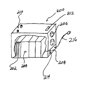
[0036]FIG. 2 illustrates one of many possible embodiments of a smart DC power
supply or power pack 200 according to the present invention. Smart power
supply 200
comprises a plurality of chemical energy cells 202, preferably packaged as
individual
batteries 204. Smart power supply 200 may comprise one or more batteries 204,
each
comprising one or more cells 202. This invention contemplates use of all type
of
battery designs, such as, but not limited to, lithium ion batteries, lead-acid
batteries,
nickel-cadmium batteries, nickel-zinc batteries; and nickel metal hydride
batteries.
The battery type chosen for a particular smart power supply 200 preferably
allows for
recharging of the cells, as is known in the art.
[0037] It will be appreciated that a universal electric motor configured to
run on about
110 to 120 volts (AC) 01 220 to 240 volts (AC), 50 to 60 HZ AC power can be
run on
DC power of lower voltage. However, it is preferred for purposes of the
present
invention, that the DC voltage supplied by the power pack 200 range from about
35%
to about 120% of the AC voltage requirements Thus, for a 120 vAC device, a
smart
power supply 200 according to the present invention may be configured to
supply
between about 42 vDC and about 144 vDC. It will be appreciated that the
decision of
what DC voltage to supply is a design choice based on the performance
6
CA 02905725 2015-09-23
. .
characteristics, operation environment and safety concerns for the device. For
example, two 25 vDC lithium ion battery may be configured in series to provide
about
50 vDC to a universal electric motor device configured to run on 120vAC. As
for the
amount of current supplied, again a person of ordinary skill in the art can
arrange the
chemical energy sources in correct amount and order to provide the necessary
power
(voltage and current) to operate the universal electric motor 100 on DC power.
[0038]Also shown in FIG. 2, smart power pack 200 also may comprise one or more
conventional 120 vAC outlets 206 (grounded or ungrounded) from which the DC
power
is supplied. It will be appreciated that the outlets 206 are sized to handle
the current
and voltage intended to be supplied.
(0039] FIG. 2 also shows an optional integral charging section 208 that is
configured to
convert AC power, such as 120vAV, 60 Hz power, into DC power for recharging
the
batteries 204. It will be appreciated that the smart power pack 200 is not
required to
have an integral charging section 208. In such case, smart power pack 200 may
have
positive and negative charging buttons 210 to which a conventional battery
charger
(not shown) may be connected, when it is desired to recharge the batteries
204.
Buttons 210 may be replaced with any manner of connector that allows the
batteries to
be recharged.
[0040] Lastly, smart power pack 200 preferably comprises an identity detection
/
validation component 212. This component is configured to control the flow of
power
between the power pack 200 and the universal electric motor, such as device
100.
For example, and without limitation, if a device having a universal electric
motor, such
as a box fan (not shown), is plugged into outlet 206, no DC power will be
supplied to
the box fan unless the box fan satisfies the requirements of the identity
detection /
validation component 212.
7
CA 02905725 2015-09-23
. .
[0041]The identity detection / validation component 212 may comprise a circuit
having
a radio frequency detection and/or transmission circuits, e.g., RFID, such
that only
devices, or portions of devices such as a device power cord, that have correct
RFID
characteristics can obtain power from the smart power pack 200. In addition to
RFID
or other wireless data transmission protocols, smart power pack 200 also may
utilize
an identity detection / validation component 212 comprising near field
communication
protocols (currently used with smart phones and other mobile devices) to
identify and/
or interrogate the device seeking to use the DC power from the smart power
pack 200.
Additionally or alternately, a power circuit 214 may be used to modulate or
otherwise
communicate information on the DC power signal to and/or from the device.
Still
further, the device's electrical signature, e.g., its noise signature, may be
utilized to
determine whether DC power should be supplied, or continued to be supplied to
the
device.
[0042] It will now be appreciated after having the benefit of this disclosure,
that other
identity detection / validation components 212 may be used, including, without
limitation, mechanical components such as, limitation, keys, magnetic switch
activation
or unique power plug or connector configuration. Electro mechanical identity
detection
/ validation components 212 may also be used including, without limitation,
Dip switch
settings, or any combination of the smart controls and mechanical.
[0043]A smart power supply 200 may be constructed to allow DC power to be
selectively supplied to only those devices having universal electric motors
that have
been approved to operate on DC power.
[0044]FIG. 3 illustrates one of many possible embodiments utilizing aspects of
the
present invention. A conventional wet/dry vacuum 300 utilizing a universal
electric
motor (not shown), such as those available from Emerson Electric Co., has been
adapted to use a smart power pack 308. The AC power cord 302 has been modified
with a smart plug 304 comprising a passive RFID chip having a particular
8
CA 02905725 2015-09-23
electromagnetic signature. The smart power pack 308 is configured, for
example,
such as described with reference to FIG. 2. This smart power pack 308
preferably
comprises a plurality of lithium ion batteries configured to supply between
about 40
and 120 vDC and more than 70 Watt-hours. In the particular embodiment
illustrated in
FIG. 3, power pack 308 comprises a mating RFID transceiver configured to
interrogate
the RFID chip 306 in the plug 304. When the plug 304 is brought near to the
power
pack 308, or plugged into the outlet/receptacle 310, the power pack identity
detection /
validation component 312 permits the power pack 308 to supply DC power to the
plug
304 / cord 302. Although RFID is used with the embodiment illustrated in FIG.
3, it will
be appreciated that any one or more of the technologies discussed above may be
used. Further, the plug 304, with its chip or other component, may tell the
power pack
identity detection / validation component 312 what voltage and/or amperage
should be
supplied by the smart power pack 308. As such, the smart power pack 308 may be
able to supply a variety of discrete voltages and/or amperages within its
range, or
between about 42 and 144 vDC and more than 70 Watt-hours in this case.
[0045] FIG 4 illustrates one of many possible alternate embodiments utilizing
aspects
of the present invention. A wet/dry vacuum 400 has been adapted to use a smart
power pack 402. This smart power pack 402 preferably comprises a plurality of
lithium
ion batteries 404 configured to supply between about 42 and 144 vDC and more
than
70 Watt-hours. The smart power pack 402 preferably also comprises a charging
section 406, a controller 408, and an AC power cord 410. In operation, the
vacuum
400 may be plugged into a supply of AC line power, such as a standard wall
outlet (not
shown) and the device 400 may be operated as usual. If the AC power is
disrupted or
unavailable for any reason (e.g., the cord 410 is inadvertently unplugged),
the
controller 408 senses the disruption in AC power and immediately (or
substantially
immediately) and automatically switches supply of power to the universal
electric
motor to the DC power supplied by the batteries 404. If AC power is restored,
the
controller 408 automatically switches power supplied to the motor back to AC
power
and recharging of the batteries is initiated, if appropriate. It is preferred
in this
9
CA 02905725 2015-09-23
embodiment that the smart power pack 402 be relatively integral with the
device so
that the power pack 402 cannot be removed and used with other devices. It will
be
appreciated that embodiments of the type illustrated and described in FIG. 4
may or
may not utilize the identity detection / validation components 212 described
above.
[0046]The various embodiments of the power pack 200, 308, 402 may include an
inverter to supply AC power to those devices not approved to operate on DC
power.
For example, when plugged into a supply of AC line power, the power pack may
supply that AC power to the device and simultaneously charge the power supply
204
or batteries 404. If the AC line power is disrupted, the power pack could
continue to
supply AC power to the device through the inverter from the power supply 204
or
batteries 404. In this embodiment, the power pack 200, 308, 402 may operate
much
like a conventional uninterruptible power supply (UPS) with respect to those
devices
not approved to operate on DC power. However, in all embodiments, the power
pack
202, 302, 402 retains many, if not all, of the other features described
herein, unlike a
conventional UPS.
[0047]The various embodiments of the power pack 200, 308, 402, 500 may be
designed as a multi-purpose job site tool. For example, as shown in FIG. 5,
FIG. 6
and FIG. 7, the power pack may include a radio 550 powered by the AC line
power
and/or the power supply 204 or batteries 404. Such a radio may include one or
two
speakers 552. The power pack may include one or more ports 560, preferably in
the
back of the power pack, to receive, charge, and/or receive power from the
power
supply 204 or batteries 404 and/or batteries for conventional cordless tools,
such as
the batteries for 12, 18, and/or 24 vDC cordless drills and the like. In this
case, the
power pack preferable includes circuitry to determine at what voltage any such
battery
should be charged. Alternatively, the power pack may rely on the physical
structure of
the batteries for determining at what voltage any such battery should be
charged, and
include multiple charging ports 560, one or more for each of 12, 18, and 24
vDC
batteries.
CA 02905725 2015-09-23
. ,
[0048]The various embodiments of the power pack 200, 308, 402, 500 may also be
daisy-chained together to maximize power available to be supplied to the load.
For
example, the various outlets/receptacles 206, 310, 506 and inlets/cords 210,
216, 410,
510 may be connected to other inlets and outlets of other power packs to
increase
power capacity. Thus, the various embodiments of the power pack 200, 308, 402,
500
may detect when they are connected to an identical pack, or another embodiment
thereof, using the identity detection / validation components described above.
Further,
the various outlets/receptacles 206, 310, 506 may also be configured to
receive power
to charge the batteries and/or pass power through in such a daisy chain
arrangement.
Likewise, the various inlets/cords 210, 216, 410 may also be configured to
supply
power to the load and/or pass power through in such a daisy chain arrangement.
[0049] Where the power pack includes the port(s) 560 described above, the
power
supply 204 or batteries 404 may not be internal to the power pack, and may in
fact be
the removable batteries designed for use with conventional cordless tools. In
this
case, the circuitry within the power pack may selectively wires these
removable
batteries in series or parallel in order to provide the required voltage and
amperage.
Alternatively, or additionally, the circuitry within the power pack may
include step-up
and/or step-down voltage converters in order to provide the required power to
the
power outlet. Such converters may provide stable, essentially constant, output
voltage
and/or power, with variable input or stored voltage or power.
[0050] The various embodiments of the power pack 200, 308, 402 may also
include a
pulse width modulator (PWM) to automatically (or manually through user input)
adjust
the power provided to the device. Such adjustment may be done in order to
accommodate the limitations of the device. Alternatively, such adjustment may
be
done in order to maximize run-time given the limited capacity of the power
supply
within the power pack 200, 308, 402. For example, as the power available in
the
11
CA 02905725 2015-09-23
,
,
power supply decreases, the power provided to the device may be decreased in
order
to maximize run-time of the device.
[005110ther and further embodiments utilizing one or more aspects of the
inventions
described above can be devised without departing from the spirit of
Applicant's
invention. For example, the power pack 402 may be designed for use with a
variety of
devices, and as such include the identity detection / validation components
212 so that
it can detect when and what voltage to supply to each of those devices. It
will also be
appreciated that the power packs described herein may be configured to deliver
other
combinations of voltage, amperage (amp-hours), and/or wattage (watt-hours).
[0052]Turning now to FIG. 8, a basic operation is described. A device
identification
module is associated with a load. A device authorization module is associated
with a
power pack of the present inventions. When in contact, or close enough, the
device
identification module and device authorization module communicate with one
another
to confirm that the load is authorized to receive DC power, as well as learn
other
characteristics and capabilities of the load, such as input voltage
requirements. If such
communications do not occur, the power pack presumes that the load is not
authorized to receive DC power, or is not connected. If the load is connected,
power
output is enabled, such that power from the power source is supplied to the
load. If
the load is authorized to receive DC power, the power supplied to the load may
be DC
power. If the load is not authorized to receive DC power, the power supplied
to the
load may only be AC power if available.
[0053]Turning now to FIG. 9, a power boost operation is described. Should the
load
require a higher voltage than is stored in the battery(ies), the output power
to the load
is boosted. Specifically, as shown, a regulator uses logic and/or other
circuitry to
boost the voltage from the battery to output to the load.
12
CA 02905725 2015-09-23
[0054]Turning now to FIG. 10, a commutation detection operation is described.
The
load need not include a specific device identification module. Rather, the
identity
detection / validation component, of the power pack, may simply detect
characteristics
of the load. For example, when the device/load is connected to the power pack,
the
identity detection / validation component may function as a commutation
detection
module and attempt to detect the commutation of the load. If the device is
detected to
be a commutated, series-wound motor, through detection logic of the identity
detection
/ validation component, the device load is determined to be authorized to
receive DC
power and the power supplied to the load may be DC power. If the device is
detected
to be a commutated, series-wound motor, the load is determined to not be
authorized
to receive DC power and the power supplied to the load may only be AC power if
available.
[0055]Turning now to FIG. 12, an advanced operation is described. Any
embodiment
many include one or more of the features described with reference to FIG. 12.
As with
FIG. 8, the device identification module and device authorization module
communicate
with one another to detect whether that the load is authorized to receive DC
power.
[0056]If the load is authorized to receive DC power, the power supplied to the
load
may be either AC power or DC power. If AC line power is detected by an input
power
detection module, then that AC line power is preferably output to the load.
That AC
line power may also be used to charge the battery(ies), through a charger. If
AC line
power is not detected by the input power detection module, then DC power from
the
battery is output to the load. Should AC line power be detected by the input
power
detection module, the power pack stops supplying DC power to the load and
starts
supplying the AC line power to the load. Likewise, should the AC line power
cease to
be detected by the input power detection module, the power pack stops
supplying the
AC line power to the load and starts supplying DC power to the load.
13
CA 02905725 2015-09-23
,
,
[0057] If the load is not authorized to receive DC power, the power supplied
to the load
will be AC power. If AC line power is detected by an input power detection
module,
then that AC line power is preferably output to the load. That AC line power
may also
be used to charge the battery(ies), through a charger. If AC line power is not
detected
by the input power detection module, then DC power from the battery is
inverted by
the inverter module and then output to the load as AC power. Should AC line
power
be detected by the input power detection module, the power pack stops
inverting DC
power for the load and starts supplying the AC line power to the load.
Likewise,
should the AC line power cease to be detected by the input power detection
module,
the power pack stops supplying the AC line power to the load and starts
inverting DC
power for the load.
[0058]The power pack of the present inventions may also be configured to
detect a
bad or damaged device or load. For example, if the identity detection /
validation
component is not able to determine whether the load is authorized to receive
DC
power, such as through the lack of authentication/identification/authorization
or faulty
communications, the power pack may simply not provide power at all to the
load. As
another example, should the load draw a higher than normal, or higher than
specified
in the device characteristics learn through communications with the device,
the power
pack may stop providing power to the load.
[0059] Further, the various methods and embodiments of the methods of
manufacture
and assembly of the system, as well as location specifications, can be
included in
combination with each other to produce variations of the disclosed methods and
embodiments. For example, while the inventions of the present invention have
been
described in terms of embodiments, each embodiment may include any or all the
features of a different embodiment. Discussion of singular elements can
include plural
elements and vice-versa.
14
CA 02905725 2015-09-23
[0060]The order of steps can occur in a variety of sequences unless otherwise
specifically limited. The various steps described herein can be combined with
other
steps, interlineated with the stated steps, and/or split into multiple steps.
Similarly,
elements have been described functionally and can be embodied as separate
components or can be combined into components having multiple functions.
[0061]The inventions have been described in the context of preferred and other
embodiments and not every embodiment of the invention has been described.
Obvious modifications and alterations to the described embodiments are
available to
those of ordinary skill in the art. The disclosed and undisclosed embodiments
are not
intended to limit or restrict the scope or applicability of the invention
conceived of by
the Applicants, but rather, in conformity with the patent laws, Applicants
intend to fully
protect all such modifications and improvements that come within the scope or
range
of equivalent of the following claims.
15