Note: Descriptions are shown in the official language in which they were submitted.
CA 02905814 2016-12-07
ANIMAL BED HAVING DUAL INDEPENDENT SUPPORT CHAMBERS
FIELD OF THE INVENTION
[0001] The present invention relates to bedding for animals. More
specifically, the present
invention relates to bedding for animals having separate and independent
support chambers for
the improved support of animals while resting and/or sleeping.
BACKGROUND
[0002] Bedding for animals is generally known in the art. Animal owners or
caretakers,
including farmers and/or zoo keepers, use various materials for animal
bedding. For example,
animal owners or caretakers often utilize natural materials, for example straw
and/or sand, as
bedding material for animals. However, using natural materials as animal
bedding material has
certain drawbacks. Natural materials have a tendency to retain excreted animal
waste, including
solid waste (c.g. manure or feces) and liquid waste (e.g. urine or milk). As
such, the animal
owners or caretakers are required to routinely remove and replace the natural
bedding materials
to maintain animal hygiene. In addition, animals will move and/or rearrange
natural bedding
material. Thus it is necessary for the animal owner or caretaker to routinely,
or even daily, groom
the natural bedding material in order to provide a supportive and comfortable
bed for the animals.
This results in the animal owners or caretakers incurring additional costs
associated with the
removal, replacement, and routine grooming of natural bedding materials,
including the costs for
labor and replacement materials.
[0003] Other material has been introduced and utilized as bedding material
for animals,
including flexible rubber matting, and bladder type mattresses filled with
air, water, padding, or
other materials. However, some of these other materials and associated
products used as animal
bedding have certain disadvantages.
[0004] For example, animal mattresses filled with filler materials, such as
flaked rubber or
foam, are typically very heavy, and are difficult to move into position. These
mattresses require
large amounts of manpower or machinery to position the mattresses for use.
Further, these
- 1 -
CA 02905814 2016-12-07
mattresses typically structurally deteriorate with use. The mattresses and
associated filler
materials typically being to deform, for example retaining the shape of the
animal. This results
in the mattresses becoming less supportive of the animal, losing any
cushioning effect.
[0005] In addition, certain single bladder type mattresses, such as U.S.
Patent No. 6,152,077
to Bristow, can cause injuries to many animals. The fluid pressure necessary
to support larger
animals in these single bladder type mattresses can lead to surface
instability, adversely affecting
the footing of the animal during the process of lying down or standing up on
the single bladder
type mattress. The surface instability can cause the animal to become
unsteady, fall, and/or roll
over, which can lead to injury to the animal.
[0006] Further, certain animals may be discouraged from using certain
single bladder type
mattresses due to surface instability. Certain animals that may use a single
bladder type mattress
arc inherently unstable. These animals may refuse to use mattresses having
surface instability, as
the animals will lose confidence in its respective ability to walk on the
unstable mattress.
[0007] In addition, single bladder type mattresses are limited to only a
single amount of
support material provided therein. Single bladder type mattresses cannot be
tailored to have
different quantities, amounts, or volumes of support material to provide
different levels of support
in different areas of an animal. For example, a single bladder type mattress
is unable to provide
one level of support for the head area of an animal and a second level of
support, different than
the first level, for the body area of the animal.
[0008] Flexible rubber matting, filled mattresses, and single bladder type
mattresses
referenced above have additional limitations. As illustrated in the '077
Patent to Bristow, the
edge of the mattress closest to the gutter area (i.e. the end of the mattress
closest to the rear of the
animal) is squared off This right angle can cause abrasions and injury to an
animal's legs and
underbelly due to the sharp edge.
SUMMARY OF THE DESCRIPTION
[0009] The present invention provides an improved animal bed having
independent support
chambers to support an animal while sleeping. The independent support chambers
are
- 2 -
CA 02905814 2016-12-07
independent from one another, and include independent fluid passages for
providing fluid to each
chamber. In addition, the disclosed animal bed provides an improved back end
margin having a
tapered end in which the bed slopes away from the support chambers. Further,
the disclosed
animal bed provides an improved back end margin having an increased length
which extends
away from the livestock bed and toward a common gutter for animal waste
commonly provided
next to and/or below the back end margin of a strip of livestock beds.
[0010] A bed for at least one animal is provided. The bed includes a strip
of belting having
a front end, a back end, and opposing sides, an animal bed having a first
fluid chamber and a
second fluid chamber, the first fluid chamber being provided within the strip
of belting and having
a first width extending between a first side and a second side of the first
fluid chamber, and the
second fluid chamber being provided within the strip of belting and having a
second width
extending between a first side and a second side of the second fluid chamber,
a first fluid supply
tube in fluid connection with the first chamber and a margin of the strip of
belting, and a second
fluid supply tube in fluid connection with the second chamber and a margin of
the strip of belting,
wherein the first and second chambers are fluidly isolated from one another,
and the first and
second fluid supply tubes are fluidly isolated from one another. The bed
further includes a third
fluid supply tube in fluid connection with the second chamber, wherein the
third fluid supply
tube extends to a margin of the strip of belting, the first, second, and third
fluid supply tubes
being fluidly isolated from one another. The strip of belting includes a front
end margin provided
between the front end and the first fluid chamber and a second end margin
provided between the
back end and the second fluid chamber, the back end margin includes an
extended portion, the
front margin extends a first length, and the extended portion extends a second
length, the second
length being greater than the first length, wherein the first length extends
from the front end to
the first fluid chamber, and the second length extends from the second fluid
chamber to the back
end, and wherein the second length is at least twice the length of the first
length.
[0011] An animal bed for supporting at least one animal is also provided.
The animal bed
includes a strip of bedding material defined by a first belt coupled to a
second belt, the strip of
bedding material having a head end opposing a rear end, and a first side
opposing a second side,
the first and second sides extend between the head and rear ends. At least one
animal bed is
- 3 -
CA 02905814 2016-12-07
provided on the strip of bedding material, the animal bed having a first
chamber provided between
the first and second belt, and a second chamber provided between the first and
second belt, the
first and second chambers being fluidly isolated from one another. An improved
back end margin
is provided between the second chamber and the rear end of the at least one
animal bed, the
improved back end margin being selected from the group consisting of: an
extended back end
margin having an extended portion, the extended portion extends a second
length being greater
than a first length of a front margin provided between the head end and the
first chamber; an
extended back end margin having an extended portion, wherein the strip of
bedding material is
provided on a pad, the pad includes a support surface and a gutter, the gutter
being separated from
the support surface by a gutter edge, wherein the gutter is provided below the
support surface, the
at least one animal bed being provided on the support surface and the extended
back end margin
extends from the support surface, along the gutter edge, and into the gutter;
a sloped portion
provided on the back end margin, the sloped portion having a decreasing
thickness from a first
end of the sloped portion to a second end of the sloped portion provided at
the rear end of the strip
of belting; and a sloped portion provided on the back end margin, the sloped
portion having an
acute angle between the sloped portion and an imaginary line through the
second belt
approximately parallel to the second belt.
[0012] An
animal bed for supporting animals is also provided. The animal bed includes a
strip of bedding material defined by a first belt connected to a second belt,
the strip of bedding
material having a first end opposing a second end, and a first side opposing a
second side, the first
and second sides extend between the first and second ends. A plurality of
animal beds are
provided on the strip of bedding material, each of the animal beds includes a
first chamber
provided between the first and second belt, a first fluid supply tube in fluid
connection with the
first chamber and extending outward to one of the first or second ends, a
second chamber provided
between the first and second belt, and a second fluid supply tube in fluid
connection with the
second chamber and extending outward to one of the first or second ends,
wherein the first and
second chambers are fluidly isolated from one another, and the first and
second fluid supply tubes
are fluidly isolated from one another to allow for independent insertion of
fluid into the first
chamber and the second chamber.
- 4 -
CA 02905814 2016-12-07
=
BRIEF DESCRIPTION OF THE DRAWINGS
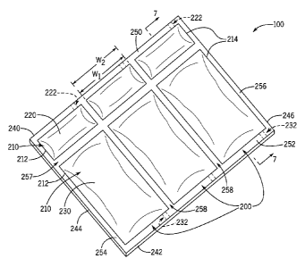
[0013] FIG. 1 is an isometric view of one or more examples of embodiments
of a strip of
animal beds, each animal bed having independent support chambers for the
support of the animal
while sleeping.
[0014] FIG. 2 is a partial exploded view of the animal bed of FIG. 1.
[0015] FIG. 3 is an isometric view of an alternative example of an
embodiment of an animal
bed having independent support chambers in accordance with the disclosure
provided herein.
[0016] FIG. 4 is a partial exploded view of the animal bed of FIG. 3.
[0017] FIG. 5 is an isometric view of an alternative example of an
embodiment of an animal
bed having independent support chambers in accordance with the disclosure
provided herein.
[0018] FIG. 6 is a partial exploded view of the animal bed of FIG. 5.
[0019] FIG. 7 is a cross sectional view of the animal bed of FIG. 1, FIG.
3, and FIG. 5, taken
along line 7-7 of FIG. 1, FIG. 3, and FIG. 5.
[0020] FIG. 8 is a cross sectional view of an alternative embodiment of the
animal bed of
FIG. 1, FIG. 3, and FIG. 5, illustrating an improved back end margin.
[0021] FIG. 9A is a sectional view of the animal bed of FIG. 1, FIG. 3, and
FIG. 5, illustrating
an example of an embodiment of an improved back end margin, taken along line 9-
9 of FIG. 8.
[0022] FIG. 9B is a sectional view of the animal bed of FIG. 1, FIG. 3, and
FIG. 5, illustrating
another example of an embodiment of an improved back end margin, taken along
line 9-9 of FIG.
8.
[0023] FIG. 10 is a cross sectional view of an alternative embodiment of
the animal bed of
FIG. 1, FIG. 3, and FIG. 5, illustrating an extended back end margin having an
extended portion.
[0024] FIG. 11 is a diagram illustrating the use of one or more examples of
embodiments of
the animal bed of FIG. 1, FIG. 3, and FIG. 5, and more specifically punching a
hole through the
top belt, bottom belt, and associated tube.
- 5 -
CA 02905814 2016-12-07
[0025] FIG. 12 is a diagram illustrating the use of one or more examples of
embodiments of
the animal bed of FIG. 1, FIG. 3, and FIG. 5, and more specifically installing
a bottom clamp
under the bottom belt and in alignment with the aperture through the bottom
belt, top belt, and
associated tube provided between the belts.
[0026] FIG. 13 is a diagram illustrating the use of one or more examples of
embodiments of
the animal bed of FIG. 1, FIG. 3, and FIG. 5, and more specifically injecting
fluid through a tube
and filling an associated first or second chamber.
[0027] FIG. 14 is a diagram illustrating the use of one or more examples of
embodiments of
the animal bed of FIG. 1, FIG. 3, and FIG. 5, and more specifically
illustrating the top clamp and
bottom clamp coupled to one another by a member in order to fluidly seal the
associated tube.
[0028] FIG. 15 is an isometric view of one or more examples of embodiments
of a system
implementing an embodiment of an animal bed having independent support
chambers in
accordance with the disclosure provided herein, and more specifically a system
to control fluid
temperature of a fluid provided in a chamber of the animal bed.
[0029] FIG. 16 is an isometric view of one or more examples of embodiments
of a system
implementing an embodiment of an animal bed having independent support
chambers in
accordance with the disclosure provided herein, and more specifically a system
to control fluid
temperature of a fluid provided in a chamber of the animal bed, the system in
communication
with the chamber from the front end of the animal bed.
DETAILED DESCRIPTION
[0030] The invention illustrated in the Figures and disclosed herein is
generally directed to a
strip 100 of animal beds 200, 300, 500 incorporating independent support
chambers 210 and an
associated method of preparing for use animal beds 200, 300, 500. It should be
appreciated that
the Figures provided herein are for illustration and are not to scale.
[0031] Referring now to the Figures, FIG. 1 illustrates one or more
examples of embodiments
of a strip of animal beds 100 incorporating a plurality of animal beds 200.
Each of the animal
- 6 -
CA 02905814 2016-12-07
beds 200 provided on strip 100 incorporate independent support chambers 210
for the support of
animals positioned thereon while sleeping.
[0032] More specifically, FIG. 1 illustrates a bed strip 100 having three
animal beds 200. In
one or more examples of embodiments, strip 100 may include a single animal bed
200 or may
include a plurality of animal beds 200. In practice, the strip of animal beds
100 will be sized
and/or customized to the available or desired space where animals sleep. The
space may include
a barn, shed, stable, or other structure in which animals sleep, or may be an
open air or outdoor
space. Additional factors for customization may include the number of animals
owned or under
the care of a user, and/or the number of animals which a user desires to have
sleep in the desired
location of the strip of animal beds 100. As an example, the strip of animal
beds 100 may be
sized less than one hundred feet in length, may equal one hundred feet in
length, or may exceed
one hundred feet in length, wherein the length of the strip of animal beds 100
is the distance
between the first and second sides 244, 246.
[0033] As illustrated in FIG. 1, each of the animal beds 200 of strip 100
is provided next to
one another, such that animals using beds 200 are generally arranged next to
one another. In
addition, animal beds 200 may be provided generally parallel to one another.
[0034] The strip of animal beds 100 may include a front end or head end 240
opposite a back
end or rear end 242. Generally, front end 240 and back end 242 may be provided
approximately
parallel to each other. Front end 240 and back end 242 may be separated by a
first side or left
side 244, and a second side or right side 246. Generally, first side 244 and
second side 246 may
be provided approximately parallel to one another. While the strip of animal
beds 100 illustrated
in FIG. 1 is generally rectangular in shape, in one or more examples of
embodiments, the strip of
animal beds may be any suitable or desired polygonal shape.
[0035] The strip of animal beds 100 is adapted to be positioned on a
support surface 400. As
illustrated in FIG. 5, strip 100 is provided atop support surface 400. Support
surface 400 may
include a gutter 410. Preferably, gutter 410 is provided adjacent or
immediately next to support
surface 400. In addition, gutter 410 may be provided a distance below support
surface 400,
separated by gutter edge 412. Accordingly, gutter 410 may be provided a
distance below strip
- 7..
CA 02905814 2016-12-07
100 positioned on top of support surface 400. This allows animal waste created
by an animal,
including solid waste and/or liquid waste, to flow into gutter 410 and away
from strip 100 and an
animal using bed 200 of strip 100. In various embodiments, support surface 400
may be any
suitable surface to support strip 100 in accordance with operation of the
associated beds 200
disclosed herein, including, but not limited to, a concrete pad, ground, or a
floor of a barn, shed,
stable, or other structure or location in which animals sleep. In addition, it
should be appreciated
that strip 100 may be secured to support surface 400. More specifically, strip
100 may be secured
to support surface 400 by adhesive, bolts, hold down strips, or any other
known or future
developed suitable method of sccurcment. As an example, strip 100 may be
secured to support
surface 400 by one or more hold down strips as disclosed in U.S. Patent No.
6,935,273 to
Throndsen et al.
[0036] Referring to FIG. 1, each animal bed 200 includes independent
support chambers or
fluid chamber or bladders 210. More specifically, each animal bed 200 includes
a first chamber
or front support 220 and a second chamber or rear support 230. The first and
second chambers
220, 230 are generally provided in alignment along an imaginary line (not
shown) extending from
the front end 240 to the back end 242 of the strip of animal beds 100. This
enables the first and
second chambers 220, 230 to respectively provide support to animals which use
an associated
bed 200.
[0037] First chamber 220 may include a first pipe or tube or chamber tube
222. First tube
222 is coupled to and in fluid connection with first chamber 220, Similarly,
second chamber 230
may include a second pipe or tube or chamber tube 232. Second tube 232 is
coupled to and in
fluid connection with second chamber 230. As illustrated in FIG. 1, first tube
222 extends from
first chamber 220 to front end 240 of strip 100 of animal beds. Second tube
232 extends from
second chamber 230 to back end 242 of strip 100 of animal beds. First tube 222
provides a user
access to fill and/or deflate first chamber 220, while second tube 232
provides a user access to fill
and/or deflate second chamber 230. For example, a user may fill first chamber
220 with fluid
through first tube 222, and separately fill second chamber 230 with fluid
through second tube
232. The separate and independent first and second tubes 222, 232 are
necessary to fill the
respective first and second chambers 220, 230, as first and second chambers
220, 230 are
- 8 -
CA 02905814 2016-12-07
independent or fluidly isolated from each other. It should be appreciated that
FIG. 1 is an example
of an arrangement of first and second tubes 222, 232 in relation to the
respective chambers 220,
230. In one or more examples of embodiments, one or both of first and/or
second tube(s) 222,
232 may separately extend from the respective chamber 220, 230 to any one of
front end 240,
back end 242, first side 244, and/or second side 246 of strip 100 of animal
beds. Further, in one
or more examples of embodiments, one or both of first and/or second tube(s)
222, 232 may
separately extend from the respective chamber 220, 230 to any one of the
margins 250, 252, 254,
256 or separating strips 257, 258 of strip 100. In addition, in one or more
examples of
embodiments, one or both of first and/or second tube(s) 222, 232 may
separately be adapted to
engage a fitting or other structural device to enable a fluid to be
introduced, retained, and/or
removed from chambers 220, 230.
[0038] First chamber 220 may have a width WI which extends between first
side 212 and
second side 214 of first chamber 220. Similarly, second chamber 230 may have a
width W2
which extends between first and second sides 212, 214 of second chamber 230.
As illustrated in
FIG. 1, the width WI of first chamber 220 is generally equal to width W2 of
second chamber 230.
In addition, as shown in FIG. 1, first side 212 of first and second chambers
220, 230 may be
provided in approximately alignment. Similarly, second side 214 of first and
second chambers
220, 230 may be provided in approximately alignment.
[0039] Strip 100 of animal beds may include a plurality of margins or end
margins 250, 252,
254, 256 provided around the perimeter of strip 100 of animal beds. As
illustrated in FIG. 1, strip
100 of animal beds may include a front end margin 250 provided between first
chamber 220 and
front end 240 of strip 100. A back end margin 252 may be provided between
second chamber
230 and back end 242 of strip 100. A first side margin 254 may be provided
between first side
244 of strip 100 and first sides 212 of the first and second chambers 220, 230
of the bed 200
closest in proximity to first side 244 of strip 100. A second side margin 256
may be provided
between second side 246 of strip 100 and second sides 214 of the first and
second chambers 220,
230 of the bed 200 closest in proximity to second side 246 of strip 100.
[0040] One or more chamber separating strips 257 may be provided between
first chamber
220 and second chamber 230 of each animal bed 200 in strip 100 of animal beds.
Chamber
- 9 -
CA 02905814 2016-12-07
separating strip 257 may extend latitudinal between first side 244 and second
side 246 of strip
100 of animal beds to divide or separate first and second chambers 220, 230 of
each respective
animal bed 200.
[0041] One or more bed separating strips 258 may be provided between each
animal bed 200
in strip 100 of animal beds. Bed separating strip 258 may extend
longitudinally between front
end 240 and back end 242 of strip 100 to divide or separate first and second
chambers 220, 230
of consecutive animal beds 200. Bed separating strips 258 may be provided
generally
perpendicular to chamber separating strip(s) 257.
[0042] Front end margin 250, back end margin 252, first side margin 254,
second side margin
256, chamber separating strip(s) 257, and bed separating strip(s) 258 provide
a sealing area to
bond and form strip 100 of animal beds. Referring to FIG. 2, strip 100 of
animal beds is formed
of a top belt 102 which is bonded to a bottom belt 104. The bonding forms a
fluid tight seal in
the sealing area defined by the margins 250, 252, 254, 256 and strips 257,
258. Top and bottom
belts 102, 104 are preferably made of an elastomeric material. The material of
top belt 102
preferably provides elasticity to top belt 102 so it may expand in the areas
of chambers 220, 230
upon the introduction of fluid to form a convex pillow-like shape (see FIG.
7), yet return to a flat
belt-like state when the fluid is removed or drained from chambers 220, 230.
The material of
bottom belt 104 preferably provides for ease of a fluid-tight bonding to top
belt 102, such as by
vulcanization. Preferably top and bottom belts 102, 104 will be made of the
respective materials
and have the respective associated properties in accordance with the
disclosure of U.S. Patent No.
6,935,273 to Throndsen et al. It should be appreciated that in various
embodiments, the materials
used for top and bottom belts 102, 104 may be the same or different. In
addition, any suitable
sealing process to bond top and bottom belts 102, 104 may be implemented,
including, but not
limited to, heat welding, sonic welding, vibrational welding, adhesives,
and/or vulcanization.
[0043] FIG. 2 is a partial exploded view of the strip 100 of animal beds
200 illustrated in FIG.
1. Referring to FIG. 2, strip 100 of animal beds is preferably formed by
aligning top and bottom
belts 102, 104. Sheets of separation foil 120, 130 may be provided between top
and bottom belts
102, 104. Specifically, a first chamber separation foil 120 and a second
chamber separation foil
130 are provided for each bed 200 in strip 100 of animal beds. First and
second chamber
- 10-
CA 02905814 2016-12-07
separation foils 120, 130 are preferably made of a material having a melting
point greater than
the temperature required to bond top and bottom belts 120, 130 together. This
allows top and
bottom belts 102, 104 to be bonded together except in the area of separation
foils 120, 130. Stated
otherwise, first and second chamber separation foils 120, 130 prevent top and
bottom belts 102,
104 from bonding in the areas where separation foils 120, 130 are in contact
with belts 102, 104.
In order to form first and second chambers 220, 230, separation foils 120, 130
have a suitable size
and/or shape to allow top and bottom belts 102, 104 to bond around the sealing
area of each
chamber 220, 230. The sealing area is defined by the front end margin 250,
back end margin 252,
first side margin 254, second side margin 256, chamber separating strip(s)
257, and/or bed
separating strip(s) 258 of each respective bed 200. The bond between belts
102, 104 around the
sealing area is fluid impervious, such that any liquid provided to first
and/or second chambers
220, 230 is isolated and retained in the respective chamber 220, 230. In
addition, first and second
chamber separation foils 120, 130 preferably are relatively thin in thickness,
the thickness being
measured as the distance of the separation foils 120, 130 being provided
between belts 102, 104,
A suitable material for separation foils 120, 130 may include, but is not
limited to, TeflonTm or
Mylar0.
[0044] Chamber tubes 222, 232 may be provided in communication with
respective
separation foils 120, 130. More specifically, a first chamber tube 222 may be
coupled to and in
communication with first chamber separation foil 120, while a second chamber
tube 232 may be
coupled to and in communication with second chamber separation foil 130. First
and second
chamber tubes 222, 232 may each be a cylindrical tube or other tubular member.
First and second
chamber tubes 222, 232 may have a melting point greater than the temperature
required to bond
top and bottom belts 102, 104 together. Accordingly, like separation foils
120, 130, first and
second chamber tubes 222, 232 prevent top and bottom belts 102, 104 from
bonding in areas
where each respective chamber tube 222, 232 is in contact with belts 102, 104,
creating a fluid
impervious seal such that any liquid provided to first and/or second chamber
tubes 222, 232 is
isolated and retained in the tubes 222, 232,
[0045] An alternative embodiment of the strip 100 of animal beds 300 is
illustrated in FIGS.
3-4. The strip 100 and associated animal beds 300 include features which are
substantially as
-11-
CA 02905814 2016-12-07
described herein in association with the strip of animal beds 100. Particular
components,
operation thereof, and manufacturing thereof as described herein are
substantially the same and
like numbers have been used to illustrate the like components.
[0046] Referring to FIG. 3, in this embodiment, strip 100 includes a
plurality of animal beds
300. Each animal bed 300 includes independent support chambers 210. The
independent support
chambers 210 include a first chambcr 320 and a second chamber 330. First tube
222 extends
from first chamber 320 to front end 240 of strip 100 of animal beds. Second
tube 232 also extends
from second chamber 330 to front end 240 of strip 100 of animal beds. First
tube 222 provides a
user access to fill and/or deflate first chamber 320, while second tube 232
provides a user access
to fill and/or deflate second chamber 330. For example, a user may fill first
chamber 320 with
fluid through first tube 222, and separately fill second chamber 330 with
fluid through second
tube 232. The separate and independent first and second tubes 222, 232 are
necessary to fill the
respective first and second chambers 320, 330, as first and second chambers
320, 330 are
independent or fluidly isolated from each other. The arrangement of first and
second tubes 222,
232 illustrated in FIG. 3 advantageously allows a user to independently fill
both chambers 320,
330 from the same side of strip 100, specifically front end 240.
[0047] First chamber 320 has a width WI, while second chamber 330 has a
width W2. The
width WI of first chamber 320 is generally less than width W2 of second
chamber 330. This is to
provide sufficient room for second tube 232 to extend from second chamber 330
to front end 240
of strip 100. In addition, first sides 212 of first and second chambers 320,
330 may be provided
in approximate alignment. However, second sides 214 of first and second
chambers 320, 330 are
offset from one another. It should be appreciated that in one or more examples
of embodiments,
second side 214 of first and second chambers 320, 330 may be provided in
approximate
alignment, while first sides 212 of first and second chambers 320, 330 are
offset from one another.
In addition, in one or more examples of embodiments, neither the first or
second sides 212, 214
of first chamber 320 may be provided in alignment with either of the first or
second sides 212,
214 of second chamber 330. In such an arrangement, the first or second sides
212, 214 of first
chamber 320 may be provided between the first and second sides 212, 214 of
second chamber
330.
- 12-
CA 02905814 2016-12-07
[0048] FIG. 4 is a partial exploded view of the strip 100 of animal beds
300 illustrated in FIG.
2. Referring to FIG. 4, strip 100 of animal beds is preferably formed by
aligning top and bottom
belts 102, 104. Sheets of separation foil 420,430 may be provided between top
and bottom belts
102, 104. Separation foils 420, 430 are substantially the same as separation
foils 120, 130, except
for the relative sizes of foils 420, 430. Specifically the width of foil 420
is less than the width of
foil 430 in order to form chambers 320, 330, such that the width WI of first
chamber 320 is
generally less than width W2 of second chamber 330 (as shown in FIG. 3).
[0049] An alternative embodiment of the strip 100 of animal beds 500 is
illustrated in FIGS.
5-6. The strip 100 and associated animal beds 500 include features which are
substantially as
described herein in association with the strip of animal beds 100. Particular
components,
operation thereof, and manufacturing thereof as described herein are
substantially the same and
like numbers have been used to illustrate the like components.
[0050] Referring to FIG. 5, in this embodiment, strip 100 includes a
plurality of animal beds
500. Each animal bed 500 includes independent support chambers 210. The
independent support
chambers 210 include a first chamber 220 and a second chamber 230. First tube
222 extends
from first chamber 220 to front end 240 of strip 100 of animal beds. However,
second chamber
230 includes a second tube 232 and a third tube 233. The second and third
tubes 232, 233 extend
from second chamber 230 to rear end 242 of strip 100 of animal beds. Second
and third tubes
232, 233 provide a user access to not only fill and/or deflate second chamber
230, but to separately
add and remove fluid from second chamber 230. Such operation is discussed in
further detail in
association with FIG. 15.
[0051] FIG. 6 is a partial exploded view of the strip 100 of animal beds
500 illustrated in FIG.
5. Referring to FIG. 6, strip 100 of animal beds is preferably formed by
aligning top and bottom
belts 102, 104. Sheets of separation foil 120, 130 may be provided between top
and bottom belts
102, 104. In addition, chamber tubes 222, 232, 233 may be provided in
communication with
respective separation foils 120, 130. Chamber tube 233 is substantially the
same as chamber
tubes 222, 232.
- 13 -
CA 02905814 2016-12-07
[0052] Referring to the strip 100 of animal beds 200, 300, 500 illustrated
in FIGS. 1-6, the
length of each bed 200, 300, 500 and the associated strip 100 as measured from
front end 240 to
back end 242 is preferably between four feet and eight feet in length, more
preferably between
five feet and seven feet in length, and more preferably is six feet in length.
In addition, the width
of each bed 200, 300 is preferably between two feet and six feet in width,
more preferably between
three feet and five feet in width, and more preferably is four feet in width.
The sizes of beds 200,
300, 500 will generally be related to the sizes of the animals to be
supported.
[0053] In one or more examples of embodiments, the strip 100 of animal beds
200, 300, 500
illustrated in FIGS. 1-6 will have a thickness, specifically the combined
thickness of top belt 102
and bottom belt 104 of preferably between six millimeters and sixty
millimeters. For example,
for certain animals, for example, but not limited to cows, each belt 102, 104
may have a thickness
of four millimeters, such that the total thickness of strip 100 is eight
millimeters. As another
example, for larger and/or heavier animals each belt 102, 104 may have a
thickness of eight
millimeters, such that the total thickness of strip 100 is sixteen
millimeters. A larger and/or
heavier animal may include, but is not limited to, bulls, moose, or other
animals larger than a
dairy cow. The thickness of each belt 102, 104 may be varied to any desired
thickness which will
adequately support an animal and enable operation of the strip 100 of animal
beds 200, 300, 500
in accordance with the disclosure provided herein.
[0054] In one or more examples of embodiments of the strip 100 of animal
beds 200, 300,
500, front end margin 250 may extend six inches from front end 240 to first
chamber 220, 320.
Back end margin 252 may extend six inches from back end 242 to second chamber
230, 330. The
width of bed separating strip 258, measured as the distance between a first
side 212 of a first bed
200, 300, 500 on one side of bed separating strip 258 and a second side 214 of
a second bed 200,
300, 500 on the opposite side of bed separating strip 258, may extend
approximately eight inches
between chambers 220, 320, 230, 330 of consecutive beds 200, 300, 500. The
distance of
chamber separating strip 257 between a first chamber 220, 320 and a second
chamber 230, 330
of a single bed 200, 300, 500 may be extend between three to four inches. It
should be appreciated
that the chamber separating strip has a width sufficient to accommodate the
size of the foot, paw,
hoof, or other type of extremity at the end of an appendage of one or more
animals using bed 200,
- 14 -
CA 02905814 2016-12-07
300, 500. In addition, it should be appreciated that the dimensions, lengths,
widths, and relative
sizes provided herein are for illustration only, and may be changed or may
differ based upon the
location of placements of strip 100, the type of animal which will use beds
200, 300, 500, the size
of animal which will use beds 200, 300, 500, or other known or future
developed factors
associated for determining the relative sizes of each animal bed 200, 300,
500, strip 100, margins
250, 252, 254, 256 and/or strips 257, 258.
[0055] FIG. 7 illustrates a cross sectional view of the strip 100 of animal
beds 200, 300, 500
illustrated in FIGS. 1, 3, and 5. More specifically, FIG. 7 illustrates a
single bed 200, 300, 500
having fluid 800 respectively provided in the first chamber 220, 320, and
second chamber 230,
330. The first chamber 220, 320 and second chamber 230, 330 are illustrated as
having a convex
pillow-like shape. The shape of the first chamber 220, 320 and second chamber
230, 330 is
provided to support animals using bed 200, 300, 500. In addition, the strip
100 of animal beds
200, 300, 500 is shown positioned adjacent gutter 410. Gutter 410 is generally
provided to collect
and foster the removal of excreted animal waste, including solid waste, such
as manure, and liquid
waste, such as urine or milk.
[0056] FIG. 8 illustrates a cross sectional view of an alternative
embodiment of the strip 100
of animal beds 200, 300, 500 shown in FIGS. 1, 3, and 5 illustrating an
improved back end margin
352. Specifically referring to FIG. 8, the improved back end margin 352 may
include a sloped
portion 362. Sloped portion 362 provides a decreasing thickness T of the top
and bottom belts
102, 104 at the back end 242 of strip 100. The decreasing thickness T is to
avoid a sharply cut
edge at back end 242 which may abrasively irritate the skin of an animal using
bed 200, 300, 500
if one or more of the legs of the animal contact, scrape, scratch, hang over
back edge 242 of back
end margin 252, or otherwise contact back edge 242 of back end margin 252.
[0057] FIG. 9A illustrates a sectional view of an example of an improved
back end margin
352 taken along line 9-9 of FIG. 8. Belt 100 is provided on a pad surface 402
of pad 400. Back
end margin 352 may have a slope or bevel or sloped portion 362. Sloped portion
362 may have
a decreasing thickness, T, from a first end 368 of sloped portion 362 to a
second end 369 of sloped
portion 362. In addition, sloped portion 362 may include a leader edge 364 on
the back end 242
extending between sloped portion 362 and the side of bottom belt 104 closest
to pad 400. Leader
- 15 -
CA 02905814 2016-12-07
edge 364 may be aligned with gutter edge 412 of gutter 410. The slope of
sloped edge 362 may
be formed by angle 0, which is defined as the angle between sloped edge 362
and an imaginary
line 366 approximately perpendicular to leader edge 364 and which extends at
the point where
leader edge 364 and sloped edge 362 meet. Angle 0 is preferably an acute
angle, more preferably
is between about twenty-five and forty-five degrees, and more specifically is
about thirty-five
degrees.
[0058] FIG. 9B illustrates a close up view of an alternative example of an
improved back end
margin 352 taken along line 9-9 of FIG. 8. Back end margin 352 may have a
slope or bevel or
sloped portion 362. The slope of sloped edge 362 may be formed by angle A,
which is defined
as the angle between sloped edge 362 and the pad surface 402 of pad 400. Angle
A is preferably
an acute angle, more preferably is between about twenty-five and forty-five
degrees, and more
specifically is about thirty-five degrees.
[0059] FIG. 10 illustrates a cross sectional view of an alternative
embodiment of the strip 100
of animal beds 200, 300, 500 shown in FIGS. 1, 3, and 5 illustrating an
extended back end margin
452. Specifically referring to FIG. 10, extended back end margin 452 may
include an extended
portion 454 which extends into gutter 410. More specifically, the additional
material 454 of
extended back end margin 452 may extend over gutter edge 412 into gutter 410.
Extended portion
454 extends a second length L2, measured as the distance between an edge of
the second chamber
230, 330 closest to back end 242 and back end 242. L2 is preferably greater
than a first length Li,
which is measures as the distance between an edge of the first chamber closest
to front end 240
and front end 240. In addition, the additional material 454 provided in the
extended portion 454
may result in back end margin 452 preferably being greater than six inches,
and more preferably
being equal to or exceeding twelve inches.
[0060] FIGS. 11-14 provide illustrations in association with a method of
filling the first
chamber 220, 320 and/or second chamber 230, 330 of each bed 200, 300, 500.
Referring to FIG.
11, a user taps an aperture or hole 520 (shown in FIG. 13) in top belt 102 in
alignment with tube
222, 232. As such, the user may utilize a die or other hole creating device
510 to puncture the
top belt 102 and bottom belt 104 (see FIG. 14) in alignment with and generally
perpendicular to
tube 222, 232. Referring to FIG. 12, once hole 520 (see FIG. 13) is tapped
through and/or
- 16-
CA 02905814 2016-12-07
penetrates both the top and bottom belts 102, 104, the user may place a bottom
closure 530, such
as a clamp, between pad 400 and bottom belt 104. Bottom closure 530 includes a
plate 532 having
a female member 534 projecting from plate 532. Female member 534 has the same
or related
outer size, diameter, and/or shape as the aperture 520 punctured through the
top and bottom belts
102, 104. After bottom closure 530 and associated female member 534 are
aligned with and
inserted into aperture 520 such that female member 534 is received by hole
520, the user may
place a fluid injection apparatus 570 into tube 222, 232. Referring to FIG.
11, fluid injection
apparatus 570 preferably has a nozzle 572 which fits within a tube access
aperture 560 provided
in line with tube 222, 232 and between first and second belts 102, 104 (see
FIG. 14). In addition
nozzle 572 preferably is of a length which will extend into tube 222, 232
beyond aperture 520.
The user may then inject fluid 800 (not shown) into the associated and
targeted first chamber 220,
320 or second chamber 230, 330. After the desired amount of fluid 800 is
injected into the
targeted chamber, the user may remove the nozzle 572 from tube access aperture
560. Referring
now to FIG. 14, the user may install a top clamp 540 over the top belt 102 and
in alignment with
aperture 520 punched through the top and bottom belts 102, 104. A member 550
is subsequently
inserted through a hole 542 provided in the top clamp 540 and into the female
member 534 of the
bottom closure 530. The user may tighten the member 550, as member 550
preferably has an
external thread adapted to mate with a complementary internal thread provided
in female member
534, drawing the top clamp 540 and bottom closure 530, together, compressing
the top and bottom
belt material 102, 104 around the aperture 520 and tube 222, 232, collapsing
tube 222, 232 and
creating a fluid tight seal. This ensures the fluid 800 injected into the
targeted first chamber 220,
320 or second chamber 230, 330 remains in the targeted chamber. The other,
remaining chambers
may be filled by repeating one or more of the above steps.
[0061] FIG. 15
illustrates one or more examples of embodiments of a system incorporating a
strip 100 of animal beds 500. More specifically, FIG. 15 illustrates a strip
100 of animal beds
500 in which second chamber 230 is temperature controlled in order to
advantageously heat or
cool animals using each bed 500. Referring to FIG. 15, each animal bed 500 of
strip 100 includes
a coupling 710 coupled to second and third tubes 232, 233 of second chamber
230. Coupling 710
may be any suitable fitting or connector for coupling a fluid supply to second
and third tubes 232,
- 17 -
233. For example, coupling 710 may be an embedded fitting embedded between top
and bottom
belts 102, 104 through tube access aperture 560 (shown in FIG. 14), a threaded
connector, flange
connector, or any other suitable known or future developed fitting or
connector for coupling a
liquid or fluid supply to second and third tubes 232, 233.
[0062] Each of the second tubes 232 may be coupled to piping or lines 739,
while each of the
third tubes may be coupled to piping or lines 738. Lines 738 may be coupled to
a liquid supply
header 740, while lines 739 may be coupled to a liquid return header 750.
Liquid supply header
740 and liquid return header 750 may then be coupled to a temperature control
system 900.
Temperature control system 900 may include various devices to assist in
controlling the
temperature of the fluid provided to second chambers 230, including, but not
limited to, a heat
source, a heat exchanger, make up fluid, one or more pumps, one or more
pressure control device,
one or more temperature control device, and / or one or more volume control
device.
[0063] In operation, fluid may be provided through supply header 740 and
piping 738 to each
respective third tube 233. The fluid subsequently is provided to each second
chamber 230. Fluid
may then be removed from each second chamber 230 through second tube 232. The
fluid may
exit through second tube 232 to piping 739 and liquid return header 750. The
liquid may then
move to temperature control system 900 where the liquid may be increased in
temperature or
decreased in temperature. The changed temperature liquid will exit temperature
control system
900 to liquid supply header 740, where the cycle will repeat. It should be
noted that the strip 100
of animal beds 500 and associated system of FIG. 15 advantageously provides
temperature to
only the second chamber 230, which generally supports the body of an animal
using each
respective animal bed 500. It is not always necessary to temperature control
the first chamber
220, as unlike the body of an animal; the head of an animal may not need
warming or cooling.
[0064] There are several advantages to the animal bed disclosed herein. The
animal bed
having independent support chambers provides better support for animal
pressure points in the
lying position. The independent and separate support chambers evenly support
and float animal
pressure points while the animal is lying on the bed. This is because the
front chamber and back
chamber are separate and unique flotation devices. Thus, the front chamber
independently
supports and floats the front pressure points, including the legs and/or knee
of an animal, while
- 18 -
CA 2905814 2017-08-29
the rear chamber independently supports and floats the rear pressure points,
including the hock,
hind legs, underbelly, underside and/or udder of the animal. In addition, both
the front and rear
pressure points of the animal are floated and/or supported at the same time,
allowing for blood to
flow through the front and rear pressure points, reducing the loss of blood
flow in these areas for
extended resting periods, and reducing the risk of injury to the pressure
points. Further, the
independent support chambers maintain a pillow of fluid in the front chamber
to cushion the knees
and/or front legs of the animal when the animal gets up. This reduces pressure
on the knees and/or
front legs of the animal when the animal gets up by reducing contact of the
knees and/or front
legs with the hard floor under the animal bed. Thus, the independent support
chambers cushion
front and rear pressure points of an animal during descent and ascent of the
animal between a
standing and lying position. The independent and separate support chambers
also prevent fluid
from traveling back and forth between chambers. This improves protection for
important pressure
points of animals, including, but not limited to, legs, knees, hocks, udders,
teats, and the underside
area of the animals. In addition, the animal bed relieves stress on pressure
points while animals
are in the lying position. This allows for blood to flow through the leg,
knee, hock, and/or udder
areas, and prevents the loss of blood flow in these areas for extended resting
periods. In addition,
the animal bed disclosed herein advantageously can be tailored to have a
desired fluid volume,
fluid pressure, and/or fluid amount to support different animals, different
areas of animals, and/or
different types of animals. In addition, the improved back end margin of the
animal bed disclosed
herein advantageously avoids a sharply cut edge at the back end of the strip
which may abrasively
irritate the skin of an animal using a bed if one or more of the legs of the
animal contact, scrape,
scratch, hang over back edge of the back end margin, or otherwise contact back
edge of the back
end margin. In addition, the improved back end margin of the animal bed
disclosed herein
advantageously improves the cleanliness of the beds and assists in the
cleaning of the beds, as
solid and/or liquid waste from the animal may flow down the improved back end
margin into the
gutter and away from each bed. The extended back end margin advantageously
provide a barrier
such that the sensitive legs of animals will be cushioned against the edge of
the gutter, improving
the physical health of animals and assisting in the avoidance of creating
injuries and/or open sores
from contact by the animal with the gutter and/or the gutter edge. In
addition, the extended back
- 19 -
CA 2905814 2017-08-29
end margin advantageously improves cleanliness of the beds and assists in the
cleaning of the
beds, as liquid waste and/or solid waste from the animal may flow down the
extended portion of
the back end margin and away from each bed. These and other advantages are
provided by the
animal bed disclosed herein.
[0065] Although various representative examples of embodiments of this
invention have
been described above with a certain degree of particularity, those skilled in
the art could make
numerous alterations to the disclosed embodiments without departing from the
scope of the
inventive subject matter set forth in the specification and claims. Joinder
references (e.g.,
attached, coupled, connected) are to be construed broadly and may include
intermediate members
between a connection of elements and relative movement between elements. As
such, joinder
references do not necessarily infer that two elements are directly connected
and in fixed relation
to each other. In some instances, in methodologies directly or indirectly set
forth herein, various
steps and operations are described in one possible order of operation, but
those skilled in the art
will recognize that steps and operations may be rearranged, replaced, or
eliminated without
necessarily departing from the scope of the present invention. It is intended
that all matter
contained in the above description or shown in the accompanying drawings shall
be interpreted
as illustrative only and not limiting. Changes in detail or structure may be
made without departing
from the scope of the invention as defined in the appended claims.
[0066] Although the present invention has been described with reference to
preferred
embodiments, persons skilled in the art will recognize that changes may be
made in form and
detail without departing from the scope of the invention.
- 20 -
CA 2905814 2017-08-29