Language selection

Search

Patent 2905927 Summary

Third-party information liability

Some of the information on this Web page has been provided by external sources. The Government of Canada is not responsible for the accuracy, reliability or currency of the information supplied by external sources. Users wishing to rely upon this information should consult directly with the source of the information. Content provided by external sources is not subject to official languages, privacy and accessibility requirements.

Claims and Abstract availability

Any discrepancies in the text and image of the Claims and Abstract are due to differing posting times. Text of the Claims and Abstract are posted:

  • At the time the application is open to public inspection;
  • At the time of issue of the patent (grant).
(12) Patent Application: (11) CA 2905927
(54) English Title: STEERING MECHANISM FOR PEDAL DRIVEN VEHICLE
(54) French Title: MECANISME DE DIRECTION POUR VEHICULE A PEDALES
Status: Dead
Bibliographic Data
(51) International Patent Classification (IPC):
  • B62K 21/00 (2006.01)
  • B62K 21/02 (2006.01)
(72) Inventors :
  • COTTER, ROBERT M. (United States of America)
(73) Owners :
  • COTTER, ROBERT M. (United States of America)
(71) Applicants :
  • COTTER, ROBERT M. (United States of America)
(74) Agent: GOWLING WLG (CANADA) LLP
(74) Associate agent:
(45) Issued:
(86) PCT Filing Date: 2014-03-12
(87) Open to Public Inspection: 2014-10-09
Availability of licence: N/A
(25) Language of filing: English

Patent Cooperation Treaty (PCT): Yes
(86) PCT Filing Number: PCT/US2014/024300
(87) International Publication Number: WO2014/165074
(85) National Entry: 2015-09-11

(30) Application Priority Data:
Application No. Country/Territory Date
61/779,701 United States of America 2013-03-13

Abstracts

English Abstract

The present invention relates to a steering assembly for a vehicle, comprising two rotatable rods, oriented vertically and having a wheel attachment means on one end wherein wheels can be rotatably secured. The rods are connected to a first cross bar in such a way that enables the steering assembly to be attached to the vehicle frame and allows the rods to rotate. The rods are also rotatably attached to a second cross bar on the opposite end of the rod in such a way as to allow the rods to rotate. The rods are also attached to a steering means in a manner that enables them to be manually rotated in unison and which in turn pivots the wheels and steers the vehicle.


French Abstract

La présente invention concerne un ensemble de direction pour un véhicule comprenant deux tiges rotatives orienté verticalement et comprenant un moyen de fixation de roues sur une extrémité, des roues pouvant être fixées de façon rotative. Les tiges sont raccordées à une première barre transversale de manière à permettre la fixation de l'ensemble de direction sur le châssis du véhicule et à permettre la rotation des tiges. Les tiges sont également fixées en rotation à une seconde barre transversale sur l'extrémité opposée de la tige de manière à permettre la rotation des tiges. Les tiges sont également fixées à un moyen de direction de manière à permettre leur rotation manuelle à l'unisson et à pivoter ensuite les roues et diriger le véhicule.

Claims

Note: Claims are shown in the official language in which they were submitted.

What is claimed is:
1. A steering assembly (FIG. 1) for a vehicle, comprising:
a. two rods (100A & B) having distal and proximal ends, oriented essentially
vertically and rotatable about an X axis, having a wheel attachment means
(101A
& B) on its distal end, wherein wheels can be rotatably secured;
b. a first cross bar (103), located between the distal and proximal ends of
the rods,
which enables the steering assembly to be attached to the vehicle frame and
allows the rods to rotate about the X axis ;
c. a second cross bar (105) connected to the proximal end of the rods
in such a way
as to allow the rods to rotate about the X axis; and
d. a steering means (104) attached to the rods in a manner that enables them
to be
manually rotated in unison about the X axis and which in turn pivots the
wheels
and steers the vehicle.
2. The steering assembly of claim 1, wherein the rods are made of aluminum.
3. The steering assembly of claim 1, wherein the first cross bar has a C
shape.
4. The steering assembly of claim 1, wherein the steering assembly
incorporates a bicycle type
handle bars.
5. The steering assembly of claim 1, wherein the steering assembly
incorporates an airplane type
handle bars.
6. The steering assembly of claim 1, wherein the steering assembly comprises;
a. a steering column; and
b. at least two cross bars connected rotatably connected to the steering
column and
connected to the rods.
4

Description

Note: Descriptions are shown in the official language in which they were submitted.


CA 02905927 2015-09-11
WO 2014/165074 PCT/US2014/024300
Steering Mechanism for Pedal Driven Vehicle
Cross-Reference to Related Application
This application claims priority to US Provisional Application having Ser. No.
61/779,701
filed March 13, 2013, contents of which are entirely incorporated by
reference.
Background of Invention
The world today is experiencing some significant changes to the climate, some
of it is
believed to be caused by to the emission of carbon dioxide by burning fossil
fuels. The
burning of carbon based fuels coverts carbon to carbon dioxide which leads to
increased
concentrations of carbon dioxide in the atmosphere which is believed to
contribute to climate
change. Certainly one of the biggest users of fossil fuels are vehicles used
for transportation
of people and things. Most of these vehicles are propelled by internal
combustion engines
which burn fossil fuels. Therefore, any practical reduction in the number of
these type of
vehicles would possibly mitigate future climate damage.
One of the ways to reduce the use of such vehicles is to increase the use of
self-propelled
non-carbon dioxide emitting vehicles such as bicycles. However, bicycles have
their
limitations. Bicycles sometimes can be difficult the roads with to see when
sharing cars and
trucks,. With the exception of recumbent bicycles, most bicycle seats are not
comfortable. In
addition, with most bicycles you are exposed to the elements.
A need exists for a non-pollution emitting vehicle that can be both self-
propelled and/or
propelled by a non-polluting motor.
Summary of Invention
The present invention relates generally to a steering assembly for a vehicle,
comprising two
rods, rotatable and oriented essentially vertically and having a wheel
attachment means on
one end wherein wheels can be rotatably secured. The rods are connected to a
first cross bar
in such a way that enables the steering assembly to be attached to the vehicle
frame and
allows the rods to rotate. The rods are also rotatably attached to a second
cross bar on the
opposite end of the rod in such a way as to allow the rods to rotate. The rods
are also

CA 02905927 2015-09-11
WO 2014/165074 PCT/US2014/024300
attached to a steering means in a manner that enables them to be manually
rotated in unison
and which in turn pivots the wheels and steers the vehicle.
Brief Description of the Drawings
Implementation of the invention will become more apparent from the detailed
description set
forth below when taken in conjunction with the drawings, in which like
elements bear like
reference numbers.
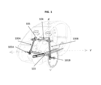
FIG. 1 is a perspective view of the steering assembly of the present
invention.
FIG. 2 is a view of the rods and wheel attachment means of the present
invention.
FIG. 3 is a view of the rods and wheel attachment as position within a
vehicle.
FIG. 4 is a view of a C shaped first cross bar attached to the vehicle frame.
FIG. 5 is a view of one embodiment of the steering assembly means.
Detailed Description of the Invention
It should be understood that the above description discloses specific
embodiments of the
present invention and are for purposes of illustration only. There may be
other modifications
and changes obvious to those of ordinary skill in the art which fall within
the scope of the
present invention which should be limited only by the following claims and
their legal
equivalents.
The steering assembly can be attached to any type of self-propelled or motor
propelled
vehicle. Such self-propelled vehicle could be a pedal type bicycle such as a
recumbent type
tricycle.
The rods (100A & B) of the present invention have a distal and proximal ends
and are
preferably cylindrical in shape. The rods should preferably be made of light
and strong
material such as metal, metal composite or plastic. Other materials of equal
weight and
strength may be suitable as well as certain grades of aluminum. The rods may
also be solid
or hollow such as a tube.
2

CA 02905927 2015-09-11
WO 2014/165074 PCT/US2014/024300
The rods have a wheel attachment means (101A & B) on its distal end. The wheel

attachments means provides a hub for the rotatable attachment of a wheel. Such
attachment
means should be made of strong and light material such as metal wherein wheels
can be
rotatably secured. The wheels can be bicycle wheels like that found on street
pedal road bike.
The first cross bar (103) as referred to herein is positioned between the
distal and proximal
ends of the rods. The cross bar enables the steering assembly to be attached
to the vehicle
frame and also allows the rods to rotate about the X axis,
The second cross bar (105) as referred to herein is connected to the proximal
end of the rods
in such a way as to allow the rods to rotate about the X axis. In addition,
the bar is connected
to the steering means (104) in such a manner that enables the manual rotation
of the two rods
in unison about the X axis, which in turn pivots the wheels and steers the
vehicle.
As used herein the steering means (104) refers to a steering mechanism which
enables the
manual rotation of the rods in unison about the X axis, which in turn pivots
the wheels and
steers the vehicle. Such steering mean can consist of a steering device like a
bike handle bars
as in shown in FIG. 1 and 5 connected through a column positioned essentially
perpendicular
to two bars connected to the rods in such a way that the rods are rotated in
unison about their
X axes.
3

Representative Drawing
A single figure which represents the drawing illustrating the invention.
Administrative Status

For a clearer understanding of the status of the application/patent presented on this page, the site Disclaimer , as well as the definitions for Patent , Administrative Status , Maintenance Fee  and Payment History  should be consulted.

Administrative Status

Title Date
Forecasted Issue Date Unavailable
(86) PCT Filing Date 2014-03-12
(87) PCT Publication Date 2014-10-09
(85) National Entry 2015-09-11
Dead Application 2020-03-12

Abandonment History

Abandonment Date Reason Reinstatement Date
2016-03-14 FAILURE TO PAY APPLICATION MAINTENANCE FEE 2016-04-04
2017-03-13 FAILURE TO PAY APPLICATION MAINTENANCE FEE 2018-02-22
2019-03-12 FAILURE TO REQUEST EXAMINATION
2019-03-12 FAILURE TO PAY APPLICATION MAINTENANCE FEE

Payment History

Fee Type Anniversary Year Due Date Amount Paid Paid Date
Application Fee $400.00 2015-09-11
Reinstatement: Failure to Pay Application Maintenance Fees $200.00 2016-04-04
Maintenance Fee - Application - New Act 2 2016-03-14 $100.00 2016-04-04
Reinstatement: Failure to Pay Application Maintenance Fees $200.00 2018-02-22
Maintenance Fee - Application - New Act 3 2017-03-13 $100.00 2018-02-22
Maintenance Fee - Application - New Act 4 2018-03-12 $100.00 2018-02-22
Owners on Record

Note: Records showing the ownership history in alphabetical order.

Current Owners on Record
COTTER, ROBERT M.
Past Owners on Record
None
Past Owners that do not appear in the "Owners on Record" listing will appear in other documentation within the application.
Documents

To view selected files, please enter reCAPTCHA code :


To view images, click a link in the Document Description column. To download the documents, select one or more checkboxes in the first column and then click the "Download Selected in PDF format (Zip Archive)" or the "Download Selected as Single PDF" button.

List of published and non-published patent-specific documents on the CPD .

If you have any difficulty accessing content, you can call the Client Service Centre at 1-866-997-1936 or send them an e-mail at CIPO Client Service Centre.


Document
Description 
Date
(yyyy-mm-dd) 
Number of pages   Size of Image (KB) 
Abstract 2015-09-11 1 72
Claims 2015-09-11 1 29
Drawings 2015-09-11 5 139
Description 2015-09-11 3 116
Representative Drawing 2015-10-06 1 25
Cover Page 2015-11-27 1 54
International Preliminary Report Received 2015-09-11 6 250
International Search Report 2015-09-11 1 54
National Entry Request 2015-09-11 3 81
Fees 2016-04-04 1 33