Note: Descriptions are shown in the official language in which they were submitted.
CA 02906153 2015-09-11
WO 2014/143832 PCT/US2014/027973
FOAM BEADS FOR PADDING AND BODY PROTECTION
CROSS REFERENCE TO RELATED APPLICATIONS
[0001] This application claims right of priority to and the benefit of
filing of U.S. App.
No. 13/835,079.
TECHNICAL FIELD
[0002] The invention relates generally to protective equipment for
absorbing, dispersing,
or deflecting impact shock. The invention has particular application to
athletic padding or
protective equipment.
BACKGROUND ART
[0003] Foam pads have long been used for various types of personal
protection
equipment in athletics, such as shoulder pads, knee and thigh pads, elbow
pads, athletic
supporters, and helmets. Foam pads are commonly constructed of large,
unifottnly thick
foam sheets to cover a particular region. Such pads are bulky and limit an
athlete's
mobility. These pads also do little to disperse the energy absorbed from an
impact. While
the foam pad absorbed some energy and force, what is not absorbed passes
through the
foam in the same direction as the direction of impact. Stated differently,
when the foam is
impacted, unabsorbed force passes straight through the pad to the underlying
region.
[0004] More recently, it has become popular to score or pellet certain
panels of foam
padding into small units, such as hexagons or squares, to allow the pad to
more easily
curve or flex about a rounded surface, and thereby to closely conform to the
body. While
this in theory may in some cases accommodate an athlete's mobility, it does
not address
the manner in which the padding absorbs, disperses, or deflects forces, which
typically
are passed in a substantially straight line vector through the pad to the
underlying area
intended for protection. In fact, traditional padding, whether segmented or
not, relies
1
CA 02906153 2015-09-11
WO 2014/143832 PCT/US2014/027973
substantially only on the padding's ability to absorb impact forces, while not
much
attention has been given to dispersing or deflecting forces.
[0005] The traditional design of football shoulder pads evidences a
reluctance to rely
upon the protective absorbing, being traditionally designed to sit raised
above the
wearer's shoulders. In such configuration, the shoulder pad is designed to
deflect
downward to absorb force, while a hard yoke component flexes to absorb
additional
energy. However, such pads suffer from a higher-than-desired profile and can
impair a
wearer from being able to comfortably turn his neck or easily raise his arms.
While
shoulder pads having increased flexibility would be welcomed, reducing the
size of a
conventional pad may increase the potential force impacting the wearer, while
the use of
pads that closely conform to the body would compete against the design
characteristics of
such shoulder pads, which must be raised above the shoulder to provide the
amount of
protection for which they are engineered, by allowing the flexing yoke to work
as
designed.
[0006] What is needed, then, is a pad better able to absorb, deflect, or
disperse impact
energy and forces, optimally while allowing for increased wearer flexibility
and mobility.
SUMMARY OF THE INVENTION
[0007] In some aspects, the invention relates to a foam padding having a
first foam pellet
having an aperture substantially near a minor axis thereof.
[0008] In other aspects, the invention relates to a foam padding having a
plurality of
foam pellets, at least one of said foam pellets having an aperture
substantially near a
minor axis thereof.
[0009] In other aspects, the invention relates to a protective foam pad
having a first
textile layer adapted to enclose a protected area; and a plurality of foam
pellets arranged
in an array and disposed along the first textile layer, where at least one
pellet has an
aperture through the pellet substantially near the minor axis.
[0010] In other aspects, the invention relates to pads for use in
athletic competitions
having a first textile layer adapted to receive an upper body of a wearer; a
second textile
2
CA 02906153 2015-09-11
WO 2014/143832 PCT/US2014/027973
layer sewn to the first textile layer to form a plurality of enclosed pockets;
and a plurality
of foam arrays arranged in the plurality of enclosed pockets, each foam array
having a
plurality of foam pellets having an aperture substantially near a minor axis
thereof, and a
substrate connecting the plurality of foam pellets.
[0011] Shoulder pads for use in athletic competitions having a padding
rig having an
inner textile layer; an outer textile layer; and a plurality of foam pellets
sandwiched
between the inner textile layer and outer textile layer, said pellets having
an aperture
substantially near a minor axis thereof, where the foam pellets are arranged
about the
padding rig.
[0012] Other aspects and advantages of the invention will be apparent
from the following
description and the appended claims.
BRIEF DESCRIPTION OF DRAWINGS
[0013] It should be noted that identical features in different drawings
are shown with the
same reference numeral.
[0014] To be completed when drawings completed.
DETAILED DESCRIPTION
[0015] First disclosed herein is a padding configuration that may be used
in shoulder
pads and other wearable equipment. While traditional padding configurations
employ
panels or sheets of foam or other padding material exhibiting substantial
uniformity
across their surface area, the inventors direct attention to constituent areas
or sizes of the
padding material.
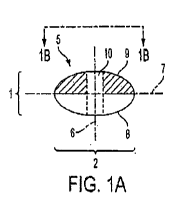
[0016] Turning to the drawings, an exemplary embodiment of a foam pellet
5 is shown in
FIGS. 1A-1C. Pellet is used to describe any mass that may be variously
described as a
ball, nugget, segment, peanut, globe, lump, spheroid, ovoid, ellipsoid,
lentoid,
polyhedron, of any flexibility, consistency, or hardness and having at least
some of the
characteristics further described in this disclosure. FIG. 1A depicts a cross-
section of a
3
CA 02906153 2015-09-11
WO 2014/143832 PCT/US2014/027973
foam pellet 5, while FIG. 1B depicts a top plan view of the same pellet 5. For
sake of
discussion, pellet 5 is shown with a height 1 and a width 2, though it will be
understood
that -height" and "width" do not necessarily bear any relation to vertical or
horizontal
orientation, and instead "height- refers to the measure taken along the minor
axis 6, and
-width" refers to the measure taken along the major axis 7. In the shown
embodiment,
pellet 5 is generally lobular, presenting a generally circular cross-section
when viewed
along the minor axis 6, and a generally elliptical or oval cross-section when
viewed along
its major axis 7. This shape is also known variously as a lentoid or oblate
spheroid. In
some embodiments, the pellet 5 has a width of approximately 1.25 inches and a
height of
approximately 1 inch. In other embodiments, the pellet 5 may have different
dimensions
corresponding to the dimension of the area being padded, or the magnitude of
protection
to be provided by the padding.
[0017] Other shapes in which the height at the perimeter of pellet 5 is
less near the
perimeter than at more central points may also be provided. For example, with
reference
to FIG. 1A, the portion of pellet 5 appearing above the major axis 7 may be
conical or
frustro-conical, or may be a three-dimensional polygon with inwardly and
upwardly
slanted sides. Alternatively, the pellet 5 may have the appearance of a torus.
Also
alternatively and as depicted in FIG. 1C, pellet 5 may be in the form of
polygonal pellet
30, having creases 31 such that when viewed along the minor axis 6 the
polygonal pellet
30 has the appearance of a hexagon. It is contemplated that still other shapes
may be
used, including those that present inner chambers or voids 11, such the
pellets 5 shown in
FIGS. 1D and 1E.
[0018] The foam used for the pellets may be open-cell or closed-cell
foam. The inventors
have identified polyurethane and ethylene-vinyl acetate (EVA) foam as having
particular
advantages, but any other foam compositions may be used, for example, [INSERT
OTHER FOATVIS].
[0019] In certain embodiments, the pellet 5 has a hole or aperture 10
passing through
pellet 5 along the direction of the minor axis. As depicted in FIG. 1A and
FIG. 1B, the
aperture 10 may be coincident with or pass directly along the polar axis 6,
such that when
4
CA 02906153 2015-09-11
WO 2014/143832 PCT/US2014/027973
viewing the pellet 5 along the polar axis 6 the aperture 10 is concentric with
the
circumference of the pellet 5. In other embodiments, the aperture 10 may be
eccentric,
such that it is not centrally located on the pellet 5. In embodiments wherein
the pellet 5
has a 1.25 inch diameter, the aperture 10 may have a 0.25 inch diameter, such
that the
pellet-aperture ratio is 5:1. The inventors have found that this pellet-
aperture ratio at this
pellet size allows the pellet 5 to absorb and deflect additional energy while
not adversely
affecting the strength or integrity of the pellet 5. Other aperture diameters
and pellet-
aperture ratios may be used without departing from the scope of this
invention.
[0020] Used together, or to a lesser degree separately, the disclosed
shape of the foam
pellet 5 and the configuration with an aperture 10 through the pellet 5
provides increased
protection for the padded object or body part. In foam pads having flat sides
that are
substantially perpendicular to the surface of the padded object, impacting
forces transfer
most of the impact energy through the pad and into the padded object. It is
believed that
prior art foam panels in such a configuration primarily respond to impacts by
compression. Without limiting the scope of the invention, the pellet 5 as
disclosed herein
is believed to have a greater capability for responding to such forces by not
only
compressing, but also by deforming to the side (e.g, its apex shifting
sideways), or by
deforming inwardly to intrude into the space presented by aperture 10. The
pellet 5 as
taught also presents additional angles for receiving the initial impact force.
The aperture
also has the additional benefit of providing increased ventilation for the
protected area.
This helps keep the wearer cool while exerting himself or herself during
typical of
athletic play.
[0021] Returning to FIG. 1A, in some embodiments the foam pellet 5 is
constructed of
foam having variable density across the cross-section of the pellet 5. For
example, in the
embodiment depicted in FIG. IA, one half 8 of the pellet 5 is formed of foam
having one
density, and the other half 9 of the pellet 5 is formed of foam having a
second, lower
density. The different density foam halves are placed adjacent one another,
and may be
bonded together, to form the pellet 5. When used to protect a wearer, the low-
density half
9 may be worn close to the body to provide additional cushioning, while the
high-density
half 8 has greater impact absorption. Other embodiments of the pellet 5 may
have more
5
CA 02906153 2015-09-11
WO 2014/143832 PCT/US2014/027973
than two regions of density (for example, two low density regions sandwiching
a higher-
density core, or a series of progressively increasing or decreasing density
regions), a
gradient of densities, or a uniform density without departing from the scope
of this
disclosure. Such a plurality of regions having different densities, within a
single pellet 5,
may be achieved by separately forming portions of the foam and coordinating
their
placement (whether permanently joined together or simply placed near one
another to
complete the pellet). Alternately, the plurality of regions having different
densities may
be constructed into a single integrally constructed pellet 5, such as by
causing a portion of
the foam material in the mold to be cured under different conditions, or with
different
composition, than other portions. For example, in a mold for which foam
material is
injected from the top, the bottom portion may be injected as a first mixture
of foam
chemical, with a second mixture ¨ or the same mixture with a different
physical treatment
(e.g., entrained air) - deposited on top.
[0022] To protect a wearer. an array of pellets 5 may be coordinated to
cover a large
surface area of the body. In some embodiments, the pellets 5 are independent
of each
other. such that each pellet 5 reacts to impact forces independently of the
other pellets 5
and can shift, expand, compress, and absorb impact forces independently of the
other
pellets 5. In such embodiments, a covering, wrap, fabric, or other enclosure
may be used
to keep the pellets 5 organized in the array about the surface.
[0023] In other embodiments, and as depicted in FIG. 2, pellets 5 in an
array are
connected by substrates 15 to cover a region. In FIG. 2, the pellets 5 are
connected
linearly by multiple substrates 15. Because the pellets 5 are connected
together, the
ability of each pellet 5 to shift about independently is reduced. However,
presenting
multiple pellets 5 connected as a unit permits the padding to be applied over
larger
surface areas while presenting the pellets 5 in a uniform or other pre-
determined
arrangement or orientation. Production may also be eased by such arrangements,
in view
of the potential uniformity and ease of handling sheets of materials as
opposed to
individual pellets 5.
6
CA 02906153 2015-09-11
WO 2014/143832 PCT/US2014/027973
[0024] The substrates 15 may be produced independently of pellets 5 and
subsequently
connected to form the array. In some configurations, the substrates 15 are
different
materials from the pellets 5, such as lines or a web of fabric, plastic, wire,
or netting.
Such materials may be adhered to the pellets such as by gluing to or piercing
through the
pellets 5. Alternately and perhaps advantageously, the substrates 15 may be
formed into
the pellets 5 as part of the manufacturing of such pellets 5. For example, if
the pellets 5
are produced by molding in which a mold for the top half of multiple pellets 5
is brought
together with a mold for the bottom half of such pellets 5, a net, web, or
fabric (or other
structure for substrates 15) could be introduced between the two mold halves
during
formation of the pellets 5. Upon curing, and release from the mold, the
pellets 5 would be
disposed in the pre-arranged configuration about the structure of the
substrates 15, with
that structure passing through the pellets 5 and effectively embedded therein.
It is also
possible to form the substrates 15 in the molding process out of the same
molding
material that is used to make pellets 5. By so doing, the pellets 5 and
substrates 15 may
be made integral to or unitary with one another. The array thus may be in the
form of a
sheet or foam panel, configured as pellets 5 dispersed about the sheet or
panel in a
desired arrangement, interconnected by thinner areas of foam.
[0025] FIG. 3 depicts an embodiment wherein an array 20 of pellets 5 are
laid out over
an area and connected by a web 17 of substrates 15, which connect pellets 5 in
two
dimensions. In this manner, a large surface may be covered and a large pad of
pellets 5
efficiently produced. In order to allow the pellets 5 to be as independent as
possible,
holes 16 are provided in the web 17 to allow for additional flexibility. The
substrates 15
could be formed as independent links between each adjacent pellet 5 if
desired, but it has
been found that using a configuration in which the holes 16 are round aids in
resistance to
tearing by avoiding point stresses that may arise at more angular junctions of
foam.
[0026] FIG. 4 depicts a side cross-section view of the array 20 depicted
in FIG. 3. In this
embodiment, high-density halves 8 are formed in a sheet 21 with the substrates
15.
Similarly, the low-density halves 9 are formed in a sheet 22 with the
substrates. The
sheets 21 and 22 are then arranged with the high-density halves 8 and the low-
density
halves 9 aligned, forming the pellets 5. In most cases the halves 8 and 9 will
be glued or
7
CA 02906153 2015-09-11
WO 2014/143832 PCT/US2014/027973
otherwise bonded together, but in some cases they may be arranged and held in
relative
position by other structures, such as a fabric covering. Holes 16 may be
formed as part of
the molding process, or may be cut following molding. Likewise, apertures 10
may be
formed as part of the molding process for the pellets 5 (whether such molding
occurs as
part of an array, or separately), or may be bored through each pellet 5 as a
subsequent
step in the manufacturing process. If both the aperture 10 and the holes 16
are to be bored
subsequent to molding, these holes may be punched by a single jig with coring
punches
for forming each.
[0027] In any given array 20, the pellets 5 may be of uniform or varying
size. For
example, in an application where the impact forces are generally uniform over
a large
area, or the protected surface area does not substantially move, shift,
translate, rotate, or
hinge (for example, a wearer's chest or torso), the pellets 5 may be of a
substantially
uniform size. In other applications, where the impact forces vary across the
protect
surface area, or the surface is one likely to deform (for example, around a
wearer's
elbow, knee, or shoulder), pellets 5 of varying sizes may be used to increase
flexibility
and provide localized protection.
[0028] The pellets 5 described above may be used in a multitude of forms
to provide
padding to a wearer, particularly in athletic contests and in workplaces where
safety from
impacts is a concern. For example, the foam pellets 5 and arrays 20 may be
used in
football shoulder pads, knee pads, thigh pads, elbow pads, helmets, braces,
chest
protectors, football kick plates, impact plates, and other athletic or
protective equipment.
The pellets 5 and arrays 20 may also be advantageously incorporated into other
equipment, such as horse blankets, saddles, cycling seats, firefighter
equipment (e.g.,
helmets, firemen's coats and pants, etc.), bomb disposal safety suits,
construction
workers' clothing, hard hats, and other protective clothing, padding, or gear.
In these
various uses, the pellets 5 and arrays 20 may be designed to particular sizes
and arranged
into padding of particular shapes to protect a given surface area commensurate
with the
standard padding used. For example, in a horse blanket, the padding may be
shaped as a
traditional blanket to protect the wearer and the horse while riding, with due
variances in
8
CA 02906153 2015-09-11
WO 2014/143832 PCT/US2014/027973
the size of the pellets to absorb or deflect impacts between horse and rider
during
standard equestrian or horse racing actions.
[0029] For further example, in some embodiments, the pellets 5 or arrays
20 of pellets 5
may be used integrated into or as a component for use with football shoulder
pads to
provide the user protection from impacts while also allowing the user to move
the arms,
shoulders, and neck relatively unhindered. Pellets 5 may be incorporated into,
or
substituted for, the padding of traditionally configured football shoulder
pads for
improved performance.
[0030] Additionally, FIG. 5 through FIG. 9 show an improved configuration
for football
shoulder pads that may incorporate the pellets 5 disclosed above in
appropriate locations.
In general, the described configuration of football shoulder pads includes a
padding rig
50, which may if desired be in the form of a shirt or vest as shown in FIG. 5,
and an outer
impact plate 4 such as depicted in FIG. 9. In the shown application, the
padding rig 50 is
placed on the wearer, then impact plate 4 is placed over the padding rig 50 to
provide a
set of football shoulder pads having inner padding and outer arches. An
exemplary
construction of these components is hereafter described.
[0031] FIG. 5 depicts a front elevation view of one embodiment of padding
rig 50 as
worn by a wearer. The padding rig 50 is shown with several pads separated by
grooves
and configured to protect the wearer while also allowing the wearer to flex or
move
freely, which may also facilitate donning of the padding rig 50.
[0032] In the embodiment of FIG. 5, the padding rig 50 has two chest pads
55 to provide
padding over the wearer's front rib cage. The chest pads 55 are separated by a
central
groove 60 aligned over the wearer's sternum. The chest pads 55 cover the front
rib cage,
extend down to be roughly level with the user's diaphragm, and wrap towards
the side of
the wearer's chest along the diaphragm. Serratus pads 65 are positioned along
the side of
the padding rig 50 between the chest pads 55 and the wearer's underarm. The
serratus
pads 65 are roughly aligned with and serve to protect the side of the rib cage
and the
user's serratus anterior muscles. The serratus pad 65 and chest pad 55 are
separated by an
anterior groove 70. The embodiment of FIG. 5 also has clavicle pads 75 located
over the
9
CA 02906153 2015-09-11
WO 2014/143832 PCT/US2014/027973
top of the shoulder between the neck and the round of the shoulder. Clavicle
pads 75 are
roughly aligned over and serve to protect the clavicle, or collarbone. A
lateral groove 80
separates each clavicle pad 75 from the respective chest pad 55. Further the
embodiment
of FIG. 5 has deltoid pads 85 to protect the deltoid muscles and the round of
the shoulder.
Each deltoid pad 85 is separated from the clavicle pad 75 by a shoulder groove
90.
[0033] Pads within the padding rig 50 as described above may use either
multiple foam
pellets 5 independently set throughout the pad, or an array 20 of pellets 5
provided within
the pad. The pellets 5 (or array 20) may be configured to have different foam
densities in
various pads. For example, small pellets 5 or uniform foam pads may be used in
the
serratus pads 65 to allow for maximum flexibility and motion of the wearer's
arms.
However, larger pellets 5 may be used in the chest pads 55, which are more
likely to be
impact locations in football, for example. Other variations in the size,
density, and
concentration of the pellets 5 or arrays 20 may be used for other pads,
depending on the
manner in which the wearer is likely to receive an impact. It is not necessary
that all
padding in the padding rig 50 be of the structure taught for pellets 5 or
arrays thereof, but
it is preferred that at least the chest pads 55 or the clavicle pads 75
incorporate such
pellets 5.
[0034] Also, while FIG. 5 depicts one configuration of pads and grooves,
other
configurations are also possible to protect the wearer. For example, a single
chest pad 55
covering the entire chest may be used. Alternatively, the chest pad 55 and
serratus pad 65
may be fused together, or the serratus pad 65 may be larger relative to the
chest pad 55
than as is depicted in FIG. 5. Similarly, the clavicle pad 75 and deltoid pad
85 may be
fused together or have different relative sizes than as shown in FIG. 5.
Furthermore, each
individual pad individual may be broken into multiple smaller sections. In
view of the
particular need for flexibility at the shoulder, as players need to raise
their arms for
catching, throwing, or tackling, the deltoid pad 85 may particularly benefit
from
sectioning into smaller arrays or individual pellets 5, to allow that region
to move by
expanding multiple spaces between multiple smaller sections, as opposed to
relying on
fewer, areas for larger expansions (and therefore a larger area exposed from
padding). A11
of these alternative embodiments and others are within the scope of this
disclosure.
CA 02906153 2015-09-11
WO 2014/143832 PCT/US2014/027973
[0035] FIG. 6 depicts an elevation view of one embodiment of the back of
the padding
rig 50. Two back pads 150 protect the wearer's upper back. The back pads 150
are
separated by a central back groove 155, similar to the central groove 60
separating the
chest pads 55. Each back pad 150 is separated from a clavicle pad 75 by a
posterior
lateral groove 160. As with the front padding, in alternative embodiments the
back pads
150 may be joined into a single pad or subdivided into multiple pads.
[00361 In some embodiments, and as depicted in FIG. 7, the chest pads 55,
serratus pads
65, clavicle pads 75, and back pads 150 may be sewn between two fabric layers
95 and
100. FIG. 7 shows an array 20 of pellets 5 connected by substrates 15 and
covered by two
layers of fabric 95 and 100. The outer fabric layer 95 covers the outside of
the padding,
while the inner fabric layer 100 is between the wearer and the pad. This two-
ply
construction protects the padding rig 50 from incidental wear and tear while
also
protecting the skin of the wearer from chafing or other potentially
uncomfortable contact
with the foam pads. In some embodiments, the outer layer 95 may be sewn to the
inner
layer 100 to form a series of grooves, as further described below, and serried
enclosed
pockets where the pads located. The serried pockets subdivide the padding rig
50. By
situating the pads in the enclosed pockets, the pads are prevented from
shifting about or
folding over during play. Rather, the pads are maintained in place by being
sandwiched
between the inner layer 95 and the outer payer 100 inside the enclosed pocket.
[0037] In other embodiments, a single-ply fabric may be used. For example,
the pads
may be adhesively attached to the front of the fabric layer 100 with an
exposed pad
surface. In such an embodiment, the fabric 100 is between the wearer's skin
and the pads.
Alternatively, the pads may be adhesively attached to the single-ply fabric
95, such that
the fabric 95 covers both the pad and the wearer, with the pads adjacent to
the skin.
[0038] While any type of fabric may be used to allow the wearer to don the
padding rig
50, the inventors have found that in some embodiments a compression fabric or
other
high tenacity stretch fabric that forms a close-fitting garment provides
additional
advantages. In particular, compression fabric conforms the pads of the padding
rig 50
close to the body and prevents the pads from shifting during the course of
play.
11
CA 02906153 2015-09-11
WO 2014/143832 PCT/US2014/027973
[0039] In some embodiments, the deltoid pads 85 may be sewn between an
outer layer 95
and inner layer 100 of the fabric, as described above with reference to FIG.
7. In other
embodiments, as depicted in FIG. 8, the deltoid pads 85 are separate from the
inner layer
75 of fabric. In this embodiment, each deltoid pad 85 is covered by an outer
layer 95 over
the outside and a middle layer of fabric 105 that wraps underneath the deltoid
pad 75 and
is attached to the inner layer 100 of fabric at a seam 110 located underneath
the deltoid
pad 75. The middle layer 105 may be formed together with the top layer 95, or
it may be
sewn into a seam with the top layer 95 along the edge of the deltoid pad 85.
In either
case, separating the deltoid pad 85 from the inner layer 100 in this manner
allows the
wearer to rotate or move the upper arm relatively independent from the deltoid
pad 85.
The inner layer 100 extends down the upper arm to form the sleeve 120.
[0040] Returning to the embodiment depicted in FIG. 5, the central groove
60, anterior
grooves 70, lateral grooves 80, and shoulder grooves 90 are each wide enough
to form a
seam 125. If the fabric is compression fabric, the seam 125 optimally should
be wide
enough to create an overlapping seam between the different layers of fabric,
such that the
seam 125 can stretch proportionally as the fabric is stretched. If compression
fabric is not
used, the seam 125 can be very thin, and the grooves can be correspondingly
thin. The
grooves are areas without padding and allow each pad to shift with the
wearer's
movements independently of the other pads. Thus the wearer can move the
muscles of his
shoulders, upper arm, upper back, and chest relatively freely, without having
to move, or
being restricted by, the remainder of the shoulder pads 50.
[0041] In some embodiments, the grooves may be sized such that when a
wearer shifts
into particular positions in which a tackle, hit, blow, or other impact is
likely to occur, the
pads shift together to simulate the appearance and provide the protection of a
single solid
pad. For example, in football, a defensive player may set himself into a
crouch with arms
extended forward to tackle the ball carrier. In this position, the chest pads
55 and serratus
pads 65 would be forced forwardly and inwardly by the wearer's stance. The
chest pads
55, which are normally separated by the central groove 60, would collapse
toward each
other until the central edges 56 of the chest pads 55 are adjacent to each
other. Similarly,
the senatus pads 65 would be forced toward the chest pads 55, such that the
interior
12
CA 02906153 2015-09-11
WO 2014/143832 PCT/US2014/027973
edges 66 of the serratus pads 65 slide next to the exterior edges 57 of the
chest pads 55.
In this manner, the serratus pads 65 and chest pads 55 form the appearance of
a single
pad across the wearer's chest in order to protect the wearer during the
impending tackle.
[0042] Similarly, the clavicle pads 75 and deltoid pads 85 can protect a
wide receiver
leaping to catch a high pass, or a quarterback in the motion of throwing a
ball. As the
wearer's arm is raised, the player's deltoid and shoulder contract toward the
neck.
Accordingly, the deltoid pad 85 shifts inwardly to sit adjacent to the
clavicle pad 75,
simulating a single, solid pad stretching over the top of the shoulder towards
the neck.
[0043] In some embodiments, and as further described with reference to
FIGS. 9-11
belowõ the padding rig 50 may be augmented with an impact plate 4. In other
embodiments, the padding rig 50 alone may be worn by the wearer to provide
protection.
This may be particularly advantageous during low- and medium-impact play, such
as
during practices where tackling is not allowed, or where the players otherwise
conduct
"no pad workouts." In "no pad workouts," players typically remove their
traditional hard
plastic and other bulky padding in order to both protect players' health long
term, deter or
limit the amount of impacts taken by the body during practice, and focus on
game
planning and strategy. The padding rig 50 described herein is suitably
flexible to allow
players to conduct practices and drills without the bulkiness of traditional
football
shoulder pads, while also providing additional protection in the event of an
inadvertent
fall, hit, tackle, or other impact. In some of these embodiments, the padding
rig 50 may
take the form of a shirt, bib, drape, or harness worn over the upper body and
abdomen,
with pads to protect the wearer where appropriate. Such embodiments of the
padding rig
50 could be used in actual gameplay, with or without the impact plate 4
described below.
[0044] In other embodiments, and having particular advantages during
games and other
high-impact play, an impact plate 4 is provided over each shoulder, in the
nature of a hard
exoskeleton or yoke 130 as shown in one embodiment in FIG. 9 to further
support the
pads of the padding rig 50 and protect the user. As depicted in FIG. 9, the
yokes 130 may
be joined to form a single construction, for example by connecting each yoke
130 with a
rigid or flexible plastic connection 136 across the front section 135 of the
yoke.
13
CA 02906153 2015-09-11
WO 2014/143832 PCT/US2014/027973
Alternatively, one yoke 130 may be separate from and move independently of the
other
yoke 130. Any hard material may be used to form the yokes 130. The inventors
have
found that recycled carbon fiber yokes 130 provide more protection than hard
plastics or
other rigid materials, as the recycled carbon fiber plates can be conformed to
the radius of
the shoulder and tend to absorb and release back impact energy rather than
transferring it
unto the wearer. Furthermore, the recycled carbon fiber can be manufactured at
a very
thin thickness (for example, 4-8 sheets of carbon fiber, resulting in a
thickness of 0.5-0.8
mm). Recycled carbon fiber sheets having this thickness is flexible and can
react to
impact forces by absorbing the impact and springing back into shape. This
allows the
yoke 130 to flex with the wearer in order to not hamper the wearer's
flexibility or
mobility. In such ultrathin embodiments, and as depicted in FIG. 9, the edge
of the yoke
130 may be surrounded by a pad or seam 131 to prevent the yoke 130 from
inadvertently
cutting into the wearer or the padding rig 50. However regular carbon fiber or
typical
hard plastics may be used without departing from the scope of this disclosure.
[0045] The yoke 130 may be constructed in the general pattern typical of
the prior art,
being essentially flat on the front and covering an area approximately four to
six inches
wide (on each side) for an adult model. In the embodiment depicted in FIG. 9,
the yoke
130 is constructed of carbon fiber as discussed above, and therefore is able
to have a
reduced profile. As shown, yoke 130 has a front section 135 that is widest at
the base of
the neck where the clavicle requires protection. However, contrary to typical
traditional
shoulder pad yokes, the yoke 130 as shown in FIG. 9 has a cut-out section
relying on a
narrower band of material to protect downward, across the bottom of the rib
cage, and
then upward again. As shown, this section looks like a "J" or a backwards ".1-
in
appearance. The omission of material in locations typically covered by
traditional
shoulder pads is most appropriate when the padding rig employs pellets 5 in
the area
exposed by the omitted material, or when the yoke 130 is constructed of carbon
fiber as
suggested, or optimally, both. Even without such aspects, the upward
projecting portion
131 of the yoke 130 serves to offset the lack of material in the yoke 130 and
thereby
provide a weight and cost savings to the yoke 130 overall, while still
maintaining a
protective profile.
14
CA 02906153 2015-09-11
WO 2014/143832 PCT/US2014/027973
[0046] Turning to the back section 145 of the yoke 130, here also cut-
outs are employed
to reduce weight and cost. As shown here, the material of the yoke 130
encircles the
cutout, as opposed to the open-sided cutout shown on the front section 135. In
consequence, the configuration of the back section 145 has an appearance
somewhat
reminiscent of a block "0- design to protect the player's back and rib cage in
the same
manner. The use of such a stronger 0 design with both sides intact on the back
as
compared to the single-sided J on the front is believed appropriate in view of
the fact that
strikes to the front are more likely to be deflected or met by the arms of the
player. The
"J- and block "0" shapes provide increased protection over the wearer's rib
cage while
also covering less space over the wearer's chest and back, thereby reducing
the weight of
the yoke 130 and any resistance against the wearer's flexibility or mobility.
This permits
the wearer to move relatively unhindered by the yoke 130, compared to stiffer
or heavier
yokes 130. Additionally, the open designs of the J and 0 shapes advantageously
contribute to ventilation to cool athletes during play. However, other shapes
for the front
section 135 and back section 145, such as solid plates, one or more strips
extending down
from the middle section 140, or plates having multiple holes or cut outs, may
be used
without departing from the scope of this disclosure.
[0047] The middle section 140 of the yoke 130 is rounded and protects the
wearer's
shoulder and clavicle. As depicted in FIG. 10, a protrusion 141 may extend
inward and
downward to protect the collarbone. As depicted in the embodiment of FIG. 10,
the front
section 135, middle section 140, and back section 145 may be formed of a
unitary
construction or mold. Because the padding is integrated into the shirt, it is
unnecessary to
include a buckle or other device to secure the yokes 130 to each other in some
embodiments.
[0048] In some embodiments, the yoke 130 may be of varying thicknesses in
different
sections in order to provide additional strength in locations where
particularly high
impacts are anticipated. In these embodiments depicted, the flexibility of the
yoke 130 in
various sections is dependent upon its thickness. For example, and as depicted
in FIGS. 9
and 10, the front section 135 and back section 145 are thinner than the middle
section 140
to provide additional flexibility across the chest and back, while the middle
section 140 is
CA 02906153 2015-09-11
WO 2014/143832 PCT/US2014/027973
thicker relative to the front section 135 and back section 145. in view of the
higher
impact forces experienced across the shoulders when a player tackles another
player. In
other embodiments, the yoke 130 may be thicker in the back section 145, for
example,
which may be particularly advantageous for wide receivers who are prone to
being
tackled from behind or in mid-air. Other variations in the thickness and/or
flexibility of
the yoke 130, including gradual increases or decreases in thickness across a
section or in
particular regions, may also be used.
[0049] In some embodiments, and as depicted in FIG. 10, to further
protect the "point" of
the shoulder and the deltoid muscle, an epaulet 165 may be attached to the
middle section
140 and extend over the deltoid pad 85. The epaulet 165 may be formed of
carbon fiber
or hard plastic. Preferably, the epaulet 165 is attached only to the yoke 130,
such that the
epaulet 165 is substantially independent of and may react to impact forces
separately
from, the deltoid pad 85. However, this is not required in all embodiments.
[0050] In some embodiments, and as depicted in FIG. 11, the yokes 130
forming the
impact plate 4 may be completely detached from the padding rig 50. In other
embodiments, the yoke 130 may be secured to the shirt by VELCROTm, double-
sided
tape, or some other detachable means of adhering the yoke 130 to the padding
rig 50. To
don embodiments of the shoulder pads that have the impact plate 4 detached
from the
padding rig 50, the wearer first puts on the padding rig 50. Then, the wearer
slips a yoke
130 over each shoulder, aligns the yoke 130 over the padding rig 50, and then
affixes the
yoke 130 to the padding rig 50 as appropriate. In other embodiments, the
impact plate 4
may be slipped over the padding rig 50 before the entire assembly is donned at
once by
the wearer.
[0051] While the shoulder pads described above are most likely to be used
in football,
similar configurations may be used for hockey, rugby, lacrosse, and field
hockey players.
Additional chest protectors for baseball or softball catchers may also have
similar
configurations.
[0052] A padding rig 50 with an impact plate 4 may be used in other
athletic and non-
athletic environments where impact protection is important. It will be
appreciated that
16
CA 02906153 2015-09-11
WO 2014/143832 PCT/US2014/027973
the padding rig 50 and the impact plate 4 may be configured in a size and
shape
appropriate to the body part or structure to be protected. For example, in
another
embodiment, a soccer shinguard has a padding rig 50 adapted to conform to the
player's
shin and has one or more pockets enclosing foam padding as described above. A
thin
impact plate 4 covers the outside of the padding. In some embodiments, the
impact plate
4 is integrated into the padding rig 50; for example, it may be sewn into the
enclosed
pocket with the foam padding. In other embodiments, the impact plate 4 may be
slid over
and attached to the padding rig 50, or the padding rig 50 may be removably
received in a
sleeve portion of the padding rig 50, giving the player the option of wearing
the hard
impact plate 4 or simply playing with the softer padding rig 50.
[0053] In other embodiments, a helmet may be formed having foam padding
on the
interior of the helmet and a hard impact plate 4 or shell on the exterior. The
same concept
may be used for football, hockey, lacrosse, and rugby helmets, as well as
firemen's hats
and construction hard hats.
[0054] In still other embodiments, the padding may be applied to any
structure where
impact forces are likely. For example, a basketball pole or football uprights
may be
wrapped in a padding rig 50 with the foam padding inside. If the padding rig
50 is used to
protect a fragile, brittle, or easily deformable structure (for example, a
thin wooden
structural column, as may be used on a patio or deck), an impact plate 4 may
be laid over
the padding rig 50 to provide additional impact protection. If, alternately,
the padding on
the structure is intended to protect players or persons that may strike the
structure, it may
be advantageous for the foam to be outward of any impact plate 4.
[0055] The embodiments provided above are intended as examples of
potential uses of
the foam padding in various applications and is not intended to limit the
scope of use or
structure of the foam padding, padding rig 50, and impact plate 4, which may
be
advantageously applied in any scenario where a need for protection against
impact forces
is anticipated or desired.
[0056] While the invention has been described with respect to a limited
number of
embodiments, those skilled in the art, having benefit of this disclosure, will
appreciate
17
CA 02906153 2015-09-11
WO 2014/143832 PCT/US2014/027973
that other embodiments can be devised which do not depart from the scope of
the
invention as disclosed here. Accordingly, the scope of the invention should be
limited
only by the attached claims.
18