Note: Descriptions are shown in the official language in which they were submitted.
CA 02906191 2015-09-11
WO 2014/145919 PCT/US2014/030771
ANTERIOR CAPSULOTOMY DEVICE AND PROCEDURE
Background
[0001] The present invention relates generally to medical devices and more
particularly
to medical devices for performing an anterior capsulotomy (capsulorrhexis).
[0002] During cataract surgery, or removal and replacement of the natural lens
of the
eye, a surgeon must enter the globe, using a small millimeter blade, to access
the
cataract, which commonly involves the centermost layer (the cortex) of the
lens.
Most often, a clear corneal suture-less incision of 3mm or less is made. The
anterior chamber is then filled with a viscoelastic substance to protect the
cornea
during cataract surgery and to maintain the integrity of the anterior chamber
when necessary. An additional incision called a paracentesis is placed at
approximately 90 (ninety degrees) to facilitate the manipulation of the
cataract
during phaco emulsification, a process that utilizes ultrasound to gently
suction
out the cataract.
[0003] Prior to the suctioning of the cataract, an opening in the capsule is
needed to
allow for the use of devices required to effectively remove cortex and nucleus
from the capsule. It is of the utmost importance that the integrity of the
anterior
(after anterior capsulotomy) and posterior capsule is maintained. Post-
operatively the capsular envelope serves as a retainer for an artificial
implant
(intra-ocular lens 004 Without the capsule, or if the structure is
compromised,
the use of a posterior implant may be contraindicated since the capsule
provides
the support needed to keep the artificial lens in place.
[0004] There are two prior art methods of performing an anterior capsulotomy.
The
first, referred to as the "can opener" technique, is an older procedure before
more
modern techniques and advanced equipment (such as the Utrata forceps) became
available. This procedure involves the surgeon making a series of small,
connected punctures using a cystotome, or bent needle, running 360 (three-
hundred and sixty degrees) around the anterior portion of the capsule,
resulting in
an opening that resembles the appearance of the top of an open can.
[0005] The second method requires the surgeon to nick the anterior portion of
the
capsule with a cystotome to create a tear in the membrane. Using an Utrata
Page 1
CA 02906191 2015-09-11
WO 2014/145919 PCT/US2014/030771
forceps, an edge of the tear is grasped and guided to create a circular
aperture in
the surface of the anterior capsule.
[0006] Both techniques require significant skill on the part of the surgeon
and generally
take years to master. Even a slight error, can result in a devastating
prognosis for
the patient. If the capsulotomy is too small, the cataract may not be removed
sufficiently, If the capsulotomy is too large or the anterior capsule tears
during
the process, extending and resulting in a posterior capsular tear, the capsule
may
not be able to support the artificial lens implant or, worse yet, there may be
a loss
of the vitreous. If a vitreous loss occurs an immediate vitrectomy is
required,
which has the potential of a lifetime of visual impairment or blindness for
the
patient. Furthermore, the use of many newer intraocular lenses require that
the
anterior capsulotomy be performed such that a circular opening with a
predetermined diameter be made.
[0007] Thus, the prior art methods for performing anterior capsulotomies
possess
inherent deficiencies that increase the likelihood of complications and
decrease
the procedure's safety. Therefore, there is a need for a means of reliably and
safely performing an anterior capsulotomy.
Summary
[0008] In one implementation, a device for performing an anterior capsulotomy
procedure is presented. The device includes a body having proximal and distal
ends. A cutting element having at least one surgical blade is rotatably
disposed
on a distal end of the body. The cutting element is attached to a pinion
comprising a plurality of gear teeth. The gear teeth on the pinion intermesh
with
gear teeth disposed on a distal end of a shaft assembly. As the shaft assembly
is
moved laterally within the body, the pinion is caused to rotate.
[0009] In another implementation, the cutting element of the device further
includes an
arcuate member having opposing first and second ends. A first surgical blade
is
attached to, or part of, the first end and a second surgical blade is attached
to, or
part of, the second end, the surgical blades extending outwardly from the
arcuate
member.
Page 2
CA 02906191 2015-09-11
WO 2014/145919 PCT/US2014/030771
[0010] In another implementation, a method of performing an anterior
capsulotomy is
presented. The method includes making an incision in an eye. The method
further includes inserting a proximal end of Applicants' device into the
incision,
bringing the at least one surgical blade in contact with an anterior capsule
wall,
moving an actuator from a first position to a second position to create an
aperture
in the anterior capsule wall.
Brief Description Of The Drawings
[0011] Implementations of the invention will become more apparent from the
detailed
description set forth below when taken in conjunction with the drawings, in
which like elements bear like reference numerals.
[0012] FIG. 1 is a prospective view of a human eyeball illustrating the prior
art practice
of performing an anterior capsulotomy;
[0013] FIG. 2 is an exemplary stylet or needle used to perform an anterior
capsulotomy
according to the prior art method;
[0014] FIG. 3 is a cross-sectional view of a human eyeball further
illustrating the prior
art method of performing an anterior capsulotomy;
[0015] FIG. 4 is a front view of a cornea after an anterior capsulotomy is
performed
according to the prior art method;
[0016] FIG. 5A is a perspective view of an exemplary anterior capsulotomy
device of
the present invention;
[0017] FIG. 5B is a perspective view of the underside of the exemplary
anterior
capsulotomy device of FIG. 5A;
[0018] FIG. 6 is a detailed view of the head of the exemplary anterior
capsulotomy
device of FIG. 5A;
[0019] FIG. 7 is a detailed view of the cutting element of the exemplary
anterior
capsulotomy device of FIG. 5A;
[0020] FIG. 8 is a detailed view of the front pulley of the exemplary anterior
capsulotomy device of FIG. 5A;
[0021] FIG. 9A depicts the insertion of the exemplary anterior capsulotomy
device of
FIG. 5A in a limbal incision;
Page 3
CA 02906191 2015-09-11
WO 2014/145919 PCT/US2014/030771
[0022] FIG. 9B depicts the process of making an incision in the anterior
capsulotomy
using the exemplary anterior capsulotomy device of FIG. 5A;
[0023] FIG. 9C provides another view of the process of making an incision in
the
anterior capsulotomy using the exemplary anterior capsulotomy device of FIG.
5A;
[0024] FIG. 9D depicts the completion of a circular incision in the anterior
capsulotomy
made using the exemplary anterior capsulotomy device of FIG. 5A;
[0025] FIG. 10A is a block diagram showing the components of an exemplary
anterior
capsulotomy device having a rack and pinion mechanism;
[0026] FIG. 10B is a block diagram showing the assembled components of the
exemplary anterior capsulotomy device of FIG. 10A;
[0027] FIG. 11 is a cutaway perspective view of the body of an exemplary
anterior
capsulotomy device using a rack and pinion mechanism;
[0028] FIG. 12A is a perspective view of an exemplary rack mechanism for use
in the
anterior capsulotomy device body of FIG. 11;
[0029] FIG. 12B is a close up view of one portion of the rack mechanism of
FIG. 12A;
[0030] FIG. 13A is a perspective view of a pinion used in certain embodiments
of an
anterior capsulotomy device;
[0031] FIG. 13B is a side view of the pinion of FIG. 13A;
[0032] FIGs. 14A, 14B, and 14C are different views of an exemplary handle for
use
with an anterior capsulotomy device;
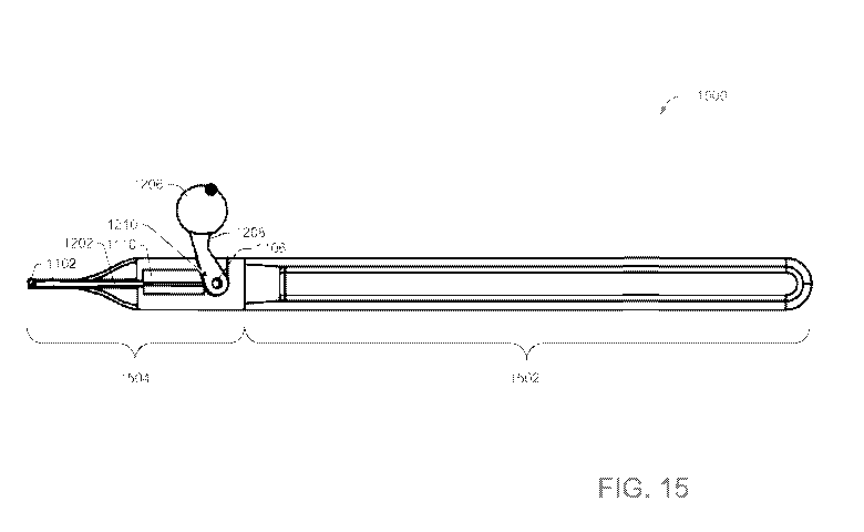
[0033] FIG. 15 shows a side view of Applicants' anterior capsulotomy device
1500;
[0034] FIG. 16 shows a cut away view of the rack and pinion mechanism disposed
within the device of FIG. 1;
[0035] FIG. 17 shows one embodiment of Applicants' cutting blade assembly;
[0036] FIG. 18 shows a second embodiment of Applicants' cutting blade
assembly;
[0037] FIG. 19 shows a third embodiment of Applicants' cutting blade assembly;
[0038] FIG. 20 shows a perspective view of Applicants' anterior capsulotomy
device
2000;
[0039] FIG. 21A shows a cross-section view of Applicants' anterior capsulotomy
device
2100, wherein actuator 2020 is disposed in a first position;
Page 4
CA 02906191 2015-09-11
WO 2014/145919 PCT/US2014/030771
[0040] FIG. 21B shows a cross-section view of Applicants' anterior capsulotomy
device
2100, wherein actuator 2020 is disposed in a second position;
[0041] FIG. 22A shows a cross-section view of Applicants' anterior capsulotomy
device
2200, wherein actuator 2020 is disposed in a first position;
[0042] FIG. 22B shows a cross-section view of Applicants' anterior capsulotomy
device
2100, wherein actuator 2020 is disposed in a second position;
[0044] FIG. 22C shows a cross-section view of a first embodiment of
Applicants'
anterior capsulotomy device 2200, wherein actuator 2020 is configured to only
permit a single use, wherein actuator 2020 is in a first position;
[0045] FIG. 22D shows a cross-section view of Applicants' anterior capsulotomy
device
2200 of FIG. 22C, wherein actuator 2020 is configured to only permit a single
use, wherein actuator 2020 is in a second and locked position;
[0046] FIG. 23A shows a cross-section view of a second embodiment of
Applicants'
anterior capsulotomy device 2200, wherein actuator 2020 is configured to only
permit a single use, wherein actuator 2020 is in a first position; and
[0047] FIG. 23B shows a cross-section view of Applicants' anterior capsulotomy
device
2200 of FIG. 23A, wherein actuator 2020 is configured to only permit a single
use, wherein actuator 2020 is in a second and locked position.
Detailed Description
[0048] This invention is described in preferred embodiments in the following
description
with reference to the Figures, in which like numbers represent the same or
similar elements. Reference throughout this specification to "one embodiment,"
"an embodiment," or similar language means that a particular feature,
structure,
or characteristic described in connection with the embodiment is included in
at
least one embodiment of the present invention. Thus, appearances of the
phrases
"in certain embodiments," "in an embodiment," and similar language throughout
this specification may, but do not necessarily, all refer to the same
embodiment.
[0049] The described features, structures, or characteristics of the invention
may be
combined in any suitable manner in one or more embodiments. In the following
description, numerous specific details are recited to provide a thorough
understanding of embodiments of the invention. One skilled in the relevant art
Page 5
CA 02906191 2015-09-11
WO 2014/145919 PCT/US2014/030771
will recognize, however, that the invention may be practiced without one or
more
of the specific details, or with other methods, components, materials, and so
forth. In other instances, well-known structures, materials, or operations are
not
shown or described in detail to avoid obscuring aspects of the invention.
[0050] The anterior capsulotomy device of the present invention is illustrated
in FIGs. 5-
9. For illustrative purposes only, FIGs. 1-4 are provided depicting the prior
art
methodology.
[0051] Referring now to FIG. 1, a human eye 110 is depicted having an anterior
capsule
122 (FIG. 3) exposed through the pupil 128 of the overlying iris 132, and the
sclera 130 (FIG. 4) circumferentially surrounding iris 132. The cornea 114
overlies anterior capsule 122, pupil 128, and iris. Historically, an anterior
capsulotomy is performed by making an initial limbal incision 112 in the
limbus
zone where sclera and iris meet. Alternatively, a clear corneal incision may
be
made instead.
[0052] As further depicted in FIG. 2, a stylet or needle 116 having a bend 118
such that
the head 120 of stylet or needle 116 can be inserted through incision 112. As
can
be seen in FIG. 3, head 120 of stylet or needle 116 is then used to make
small,
overlapping tears in anterior capsule 122 to form an opening that can be used
to
remove the original lens 124 and insert an artificial one. Specifically, the
process
requires the repeated puncturing of anterior capsule 122 with head 120 of
stylet
or needle 116 and pulling on the stylet or needle 116, each time making small
tear in the anterior capsule 122. As shown in FIG. 4, this repeated tearing of
anterior capsule 122 forms a jagged opening 126 in anterior capsule 122.
[0053] With the foregoing background information, the operation and utility of
the
instrument of the present invention may now be explained and fully understood.
Referring now to FIGs. 5A and 5B, the anterior capsulotomy device 200 of the
present invention generally comprises a body 202, wherein the proximal end is
tapered to a head 206 and the distal end acts as a handle portion 204. Device
200
further comprises a front pulley 210 connected to a cutting element 208,
wherein
a portion of front pulley 210 extends through an opening in head 206 to attach
to
cutting element 208.
Page 6
CA 02906191 2015-09-11
WO 2014/145919 PCT/US2014/030771
[0054] Actuator 214 is attached to body 202 such that actuator 214 can be
moved by a
thumb of a user. Actuator 214 is connected to rear pulley 216 via connecting
element 218 (FIG. 5B only) such that, when moved, actuator 214 causes rear
pulley 216 to rotate. Rear pulley 216 is in turn connected to front pulley 210
by
connecting element 212, such that rotation of rear pulley 216 causes rotation
of
front pulley 210 and cutting element 208.
[0055] In certain embodiments, connecting element 212 comprises a
continuous
assembly. In certain embodiments, connecting element 212 comprises a cable.
In other embodiments, connecting element 212 comprises a belt. In yet other
embodiments, connecting element 212 comprises a cord. In
certain
embodiments, connecting element 212 is formed from a plastic. In other
embodiments, connecting element 212 comprises a metal.
[0056] As depicted in FIGs. 5A and 5B, actuator 214 is mechanically
operated by a
thumb of a user. In certain embodiments, actuator 214 is rotated by the user.
In
other embodiments, actuator 214 is depressed by the user. As will be clear to
one of ordinary skill in the art, other types of actuators may be used in
place of
actuator 214 without departing from the scope of the disclosure.
[0057] In the illustrated embodiment of FIG. 5B, body 202 is illustrated as
being formed
to include groove 220. In other embodiments, anterior capsulotomy device 200
is not formed to include such a groove.
[0058] Referring now to FIGs. 6 and 7, cutting element 208 is rotatably
disposed on head
206 and is attached thereto by front pulley 210. Member 408 (FIG. 8) is
attached
to front pulley 210, and extends through head 206, and couples to the
periphery
of aperture 226 (FIG. 7) formed in cutting element 208, thereby securing
cutting
element 208 to head 206 while allowing cutting element 208 to rotate with
front
pulley 210.
[0059] In the illustrated embodiments of FIG. 6 and 7, cutting element 208
comprises
two (2) surgical blades, namely blade 222 and blade 224, disposed on opposite
ends of cutting element 208 and projecting in a downward direction. In certain
embodiments, blades 222 and 224 are formed on cutting element 208 such that
cutting element 208 and blades 222 and 224 are a single, contiguous formation.
In other embodiments, blades 222 and 224 are disposed on cutting element 208.
Page 7
CA 02906191 2015-09-11
WO 2014/145919 PCT/US2014/030771
[0060] In certain embodiments, only the leading edges of blades 222 and 224
are cutting
edges. In other embodiments, both the leading and trailing edges of blades 222
and 224 are cutting edges. In such an embodiment, cutting element 208 may be
rotated in either a clockwise or counterclockwise direction without affecting
the
device's ability to cut the anterior capsulotomy.
[0061] In certain embodiments, blades 222 and 224 comprise one or more metals.
In
certain embodiments, blades 222 and 224 comprise the same substance as cutting
element 208. In yet other embodiments, blades 222 and 224 comprise a different
substance than cutting element 208.
[0062] Turning to FIG. 8, the exemplary embodiment of front pulley 210 is
shown as
having member 408, which extends through head 206 (FIGs. 5A, 5B, and 6) and
aperture 226 (FIG. 7) to secure cutting element 208 (FIGs. 5A, 5B, 6, and 7)
to
head 206. As will be understood by one of ordinary skill in the art, cutting
element 208 may be rotatably attached to head 206 by a means other than front
pulley 210 without departing from the scope of the disclosed invention.
[0063] In certain embodiments, front pulley 210 is formed such that member 408
is
substantially cylindrical having one flat side (illustrated in FIG. 6) that
abuts a
flat side of aperture 226 (FIG. 7). In other embodiments, member 408 and
aperture 226 may have other configurations.
[0064] As illustrated in FIG. 8, front pulley 210 additionally comprises
sheave 410
formed to include groove 404 disposed between upper flange 402 and lower
flange 406 along the circumference of sheave 410. When connecting cutting
element 208 (FIGs. 5A, 5B, 6, and 7) to head 206 (FIGs. 5A, 5B, and 6), lower
flange 406 rests on top of head 206 while member 408 extends through head 206
and into aperture 226 (FIG. 7). Connecting element 212 (FIGs. 5A and 5B) then
rests within groove 404.
[0065] One feature of the present invention is that the cutting element does
not need to
make a full 360 degree rotation when actuated by the actuator. Rather, the
cutting element can make a circular incision by being rotated about 180
degrees.
In certain embodiments, the cutting element comprises two blades, such as
blades 222 and 224 (FIGs. 6 and 7), located at opposing ends of the cutting
Page 8
CA 02906191 2015-09-11
WO 2014/145919 PCT/US2014/030771
element. In these embodiments, the rotation causes each blade to make a
contiguous semicircle incision of a predetermined diameter. In
certain
embodiments, the cutting element is rotated more than 180 degrees, and
therefore, the ends of each semicircle overlap to form a single, circular
incision.
[0066] The amount of the overlap is small to prevent and/or minimize
tearing of the
anterior capsulotomy in the area of the overlap. As is known by one of
ordinary
skill in the art, repeatedly cutting the same area of the anterior capsule
wall
increases the likelihood of tearing. In certain embodiments, the arcs cut by
each
blade of the cutting element overlap by two (2) degrees at either end. In such
an
embodiment, the cutting element rotates 182 degrees when actuated.
[0067] As will be clear to one of ordinary skill in the art, by having two
opposing
surgical blades, the overall sheer stress experienced by the anterior capsule
wall
is minimal compared to the sheer stress created by a cutting instrument having
a
single blade. As is known by one of ordinary skill in the art, sheer stress
causes
deformation of a material by slippage along a plane parallel and/or tangential
to
the imposed stress. This deformation increases the likelihood that the
anterior
capsule wall will tear. By utilizing two surgical blades, each moving in
opposite
directions at the same time and applying the same stress, each blade generates
a
sheer stress of equal value in opposing directions, thereby theoretically
resulting
in a net sheer stress of zero. As will be understood by one of ordinary skill
in the
art, the natural presence of imperfections, varying thickness, etc. will
result in an
actual net sheer stress that is slightly greater than zero.
[0068] As will be apparent to one of ordinary skill in the art, the diameter
of the cut made
by the cutting element is equal to the distance between the two blades. In
certain
embodiments, this distance is adjustable. In other embodiments, the disclosed
anterior capsulotomy device may come in varying sizes, each having a different
distance between the blades.
Alternatively, the cutting head may be
interchangeable; different cutting heads having blades spaced different
lengths
apart.
[0069] Turning now to FIGs. 9A-9D, the manner of performing a capsulotomy
using the
present invention is illustrated. Each of the FIGs. depict a human eye 300
having
an anterior capsule 312 exposed through the pupil 304 of the overlying iris
302,
Page 9
CA 02906191 2015-09-11
WO 2014/145919 PCT/US2014/030771
and the sclera 314 circumferentially surrounding iris 302. The cornea 310
overlies anterior capsule 312, pupil 304, and iris 302. Initially, head 206 of
the
disclosed device is inserted through a small limbal incision 308 and the
cutting
element is placed in contact with the wall of the anterior capsule 312. In
certain
embodiments, head 206 is alternatively inserted through a clear corneal
incision.
By using the actuator (not shown), the cutting element is rotated in the
manner
depicted in FIGs. 9B-9D. The blades at ends 208a and 208b of the cutting
element cut opposing arcs 306a and 306b, shown in FIGs. 9B and 9C. As
discussed, the cutting element makes a slightly greater then 180 degree
rotation
thereby causing arcs 306a and 306b to overlap, forming circular opening 306
shown in FIG. 9D. At this point, head 206 is withdrawn and the cut portion of
the anterior capsulotomy wall may then be removed through limbal incision 308
using a probe or other device.
[0070] FIGs. 10A and 10B illustrate portions of Applicants' anterior
capsulotomy device
1500 (FIG. 15). Many details have been omitted from the block diagrams in
FIGs. 10A and 10B for the purpose of clarity. As such, the lack of a
particular
detail should not be viewed as limiting. In addition, other FIGs. discussed
herein
provide additional details omitted from FIGs. 10A and 10B.
[0071] Body 1100 includes a handle 1004 and an arm 1006. An aperture 1008 is
formed
in arm 1006. A blade assembly 1010 includes blade arm 1012. An aperture
1028 is formed in blade arm 1012. Surgical blades (not shown in FIG. 10A) are
positioned at the ends 1014 and 1016 of blade arm 1012. Pinion 1300 includes
gear teeth 1310. A rack assembly 1200 includes a shaft 1202 and gear teeth
1204.
[0072] Turning to FIG. 10B, blade assembly 1010 is attached to body 1100 via
pinion
1300. Pinion 1300 extends outwardly from aperture 1008. The rack assembly
1200 is positioned within the body portion 1002 such that the gear teeth 1204
on
the shaft 1202 intermesh with the gear teeth 1310 on the pinion 1300. Lateral
movement of the shaft 1202 (as indicated by arrow 1030) will cause the blade
assembly 1010 to rotate.
Page 10
CA 02906191 2015-09-11
WO 2014/145919 PCT/US2014/030771
[0073] FIG. 11 shows body 1100 split longitudinally with one side removed
for
illustrative purposes. The body 1100 includes an upper handle portion 1116 and
an arm 1114. Aperture 1008 is formed in the tip of the arm 1114. The aperture
1008 receives pinion 1300 which is connected to blade assembly 1010.
[0074] A channel 1104 is formed within arm 1114. The channel 1104 communicates
with a first end of cavity 1110. A second end of cavity 1110 communicates with
activation slot 1108. A pivot member 1106 is formed within activation slot
1108. A handle cavity 1112 is formed in the upper handle portion 1116 and is
configured to receive an extended handle (not shown).
[0075] In certain embodiments, the body 1100 is formed from a metal. In
certain
embodiments, the body 1100 is formed from a liquid crystal polymer, such as
ZENITE sold in commerce by Ticona LLC. In certain embodiments, the body is
comprised from any material that can be sterilized using ethylene oxide
sterilization, gamma irradiation, or autoclaving.
[0076] Referring to FIGs. 12A and 12B, rack assembly 1200 comprises a shaft
1202. In
certain embodiments, shaft 1202 comprises horizontal member 1216 and support
member 1218. The support member 1218 strengthens and stabilizes the
horizontal member 1216. Gear teeth 1204 are formed on a distal end of
horizontal member 1216. In certain embodiments the support member 1218 and
the horizontal member 1216 are formed from different materials. In certain
embodiments, the support member 1218 and the horizontal member 1216 are
formed from the same material. In certain embodiments, the horizontal member
1216 is formed from metal or a liquid crystal polymer. In certain embodiments,
the support member 1218 and the horizontal member 1216 are integrally formed.
In different embodiments, the support member is formed from metal or a liquid
crystal polymer.
[0077] Shaft 1202 is coupled to activation member 1208. End 1212 (FIG. 16) is
inserted
into aperture 1210. An aperture 1212 is formed in activation member 1208. In
certain embodiments, activation member 1208 is formed from metal or a liquid
crystal polymer. In certain embodiments, activation member 1208 is formed
from metal or a liquid crystal polymer. FIG. 12B illustrates gear teeth 1204
disposed on, or integrally formed in, a distal end of horizontal member 1216.
Page 11
CA 02906191 2015-09-11
WO 2014/145919 PCT/US2014/030771
[0078] Referring to FIGs. 11, 12A and 12B, shaft 1202 is disposed within
channel 1104
and cavity 1110. Activation member 1208 is disposed within activation slot
1108 such that pivot member 1106 extends through aperture 1212. The top
portion of activation member 1208 as well as the activation head 1206 extend
outwardly from body 1100.
[0079] Activation member 1208 moves within the activation slot 1108 by
pivoting about
pivot member 1106. Rotational movement of activation member 1208 causes
lateral movement of shaft 1202 within channel 1104. Gear teeth 1204 on
horizontal member 1216 intermesh with gear teeth 1310 on pinion 1300. Lateral
movement of the shaft 1202 causes rotational movement of pinion 1300.
[0080] Referring to FIGs. 13A and 13B, pinion 1300 includes a blade
assembly
mounting member 1302. Blade assembly mounting member 1302 includes
mounting clips 1304. Blade assembly 1010 is attached to pinion 1300 by sliding
blade assembly 1010 onto the blade assembly mounting member 1302 and over
the mounting clips 1304. The mounting clips 1304 thereby retain the blade
assembly on the pinion mounting member 1302.
[0081] Pinion 1300 includes rotation sleeve 1306. Rotation sleeve 1306 extends
through
aperture 1102 formed in body 1100 in FIG. 11.
[0082] Pinion 1300 includes a head 1308. Pinion head 1308 includes gear teeth
1310. In
certain embodiments, gear teeth 1310 are disposed around a portion of the
perimeter of the head 1308, such that the lateral motion of shaft 1202 will
cause
the pinion to rotate no more than 182 degrees. In certain embodiments, gear
teeth 1310 are arranged around a portion of the perimeter of the head 1308,
such
that the lateral motion of the shaft 1202 will cause the pinion to rotate more
than
182 degrees. In certain embodiments, gear teeth 1310 are arranged around the
entire perimeter of the head 1308, such that lateral motion of the shaft 1202
will
cause pinion 1300 to rotate 360 degrees.
[0083] Turning to FIG. 13B, dashed line 1312 corresponds to a rotational axis
of the
pinion 1300. In certain embodiments, gear teeth 1310 are disposed over more
than one half of the periphery of pinion head 1308 to enable pinion 1300 to
rotate
about 182 degrees.
Page 12
CA 02906191 2015-09-11
WO 2014/145919 PCT/US2014/030771
[0084] Referring to FIGs. 14A, 14B, and 14C, handle 1400 comprises
connection
adapter portion 1404 that tapers into a flat handle portion 1402. The adapter
portion 1404 couples, in certain embodiments, to the handle adjacent cavity
1112
(see FIG. 11). FIG 14B is an end view of the handle 1400. FIG. 14C is a
perspective view of the handle 1400.
[0085] Referring to FIG. 15, Applicants' anterior capsulotomy device 1500
comprises a
handle portion 1502 coupled to a head portion 1504. The head portion 1504 is
shown in cross section. Aperture 1102 is formed in the tip of the head portion
1504. Channel 1104 is formed in the head portion 1504. Channel 1104
communicates with cavity 1110.
[0086] Activation member 1208 is rotationally disposed in the head portion
1504 about
pivot member 1106. Activation head 1206 is connected to activation member
1208.
[0087] Referring now to FIG. 16, as activation member 1208 rotates about pivot
member
1106, shaft 1202 is caused to move laterally in channel 1104, thereby causing
pinion 1300 to rotate cutting blade assembly 1010.
[0088] Referring now to FIG. 19, in certain embodiments cutting blade assembly
1010
comprises four surgical blades, 1710A, 1710B, 1710C, and 1710D, wherein each
surgical blade is disposed on an arm, wherein the arms extend outwardly from a
center portion and are each offset by 90 degrees from the adjacent arms. In
certain embodiments, the number and pitch of gear teeth 1310 and 1204 are
selected such that the full linear movement of the shaft 1202 will result in
rotational movement of the pinion by about 92 degrees. In certain embodiments,
the number and pitch of gear teeth 1310 and 1204 are selected such that the
full
linear movement of shaft 1202 will result in rotational movement of the pinion
by between about 90 and about 100 degrees.
[0089] Referring now to FIG. 18, in certain embodiments, blade assembly
1010
comprises a single surgical blade 1710. In these embodiments, the number and
pitch of gear teeth 1310 and 1204 are selected such that the full linear
movement
of the rack assembly will result in rotational movement of the pinion by about
362 degrees.
Page 13
CA 02906191 2015-09-11
WO 2014/145919 PCT/US2014/030771
[0090]
Referring now to FIG. 17, in certain embodiments, surgical blade 1710A and
1710B are angled relative to blade arm 1012, respectively. In
certain
embodiments, the angle is
about 90 degrees. In certain embodiments, the
angle is less than 90 degrees. In certain embodiments, the angle is greater
than 90 degrees. In certain embodiments, surgical blades 1710A and 1710B each
have two cutting edges that converge at an apex such that the blade assembly
is
capable of cutting in two rotational directions.
[0091] In certain embodiments, the blade arm 1012 is planar. FIG. 18 shows a
planar
blade arm 1012. In certain embodiments, the blade arm 1012 is curved such that
the blade assembly 1010 forms an arcuate structure. FIG. 17 shows an arcuate
blade arm 1012. In the illustrated embodiment of FIG. 17, blade arm 1012
comprise a radius of curvature. Further in the illustrated embodiment of FIG.
17,
blade arm 1012 comprises a length. In certain embodiments, the radius of
curvature substantially equals the length. By "substantially equals,"
Applicants
mean the same dimension plus of minus about 10 percent. In certain
embodiments, the radius of curvature does not substantially equal the length.
In
certain embodiments, the selection of a blade assembly 1010 with a particular
radius of curvature is based on the dimensions of the patient's eye.
[0092] In certain embodiments, the surgical blades 1014 and 1016 extend
away from
blade arm 1012, respectively, such that the blades are parallel (i.e., the
distance
between the cutting edge of each blade is the same as the distance between the
base of each blade). In certain embodiments, the surgical blades 1014 and 1016
extend away from blade arm 1012, respectively, at an inward angle (i.e., the
distance between the cutting edge of each blade is closer than the distance
between the base of each blade).
[0093] In certain embodiments, the blade assembly 1010 is held in place by
mounting
clips on the bottom portion of pinion 1300. In certain embodiments, the blade
assembly 1010 is releaseably attached to the bottom portion of the pinion 1300
to
enable the blade assembly 1010 to be exchanged or replaced.
[0094] In certain embodiments, the range of motion of the activator member
1208 within
activator slot 1108 and the gear pitch on the shaft 1202 and the pinion 1300
is
Page 14
CA 02906191 2015-09-11
WO 2014/145919 PCT/US2014/030771
selected such that a full range of motion of the activator member 1208 will
cause
the blade assembly 1010 to rotate 182 degrees.
[0095] In certain embodiments, the shaft 1202 is flexible to allow the shaft
to flex as the
slot 1210 arcs around pivot member 1106.
[0096] In certain embodiments, the shaft 1202 is rigid and activator
member 1208 is
formed to include a vertical slot. The shaft 1202 is attached to the activator
member 1208 by a pin that is disposed within the vertical slot. As the
activator
member 1208 is pivoted within the activator slot 1108, the pin travels up and
down along the vertical slot, thereby allowing the shaft to remain straight
while
the shaft 1202 moves longitudinally within cavity 1104.
[0097] FIG. 20 illustrates Applicants' Anterior Capsulotomy Device 2000.
Device 2000
comprises body portion 2010, actuator 2020, and head portion 2030. In certain
embodiments, head portion 2030 extends outwardly from body portion 2010 at
an angle.
[0098] Referring now to FIG. 21A, Applicants' Anterior Capsulotomy Device 2000
comprises an elastomeric, bendable, shaft 1202 (FIG. 12) comprising a distal
end
1216 (FIG. 12) formed to include gear teeth 1204 (FIGs. 12A, 12B) disposed
within body portion 2110 and extending into head portion 2130 via channel
1104. Gear teeth 1204 intermesh with gear teeth 1310 (FIGs. 13A, 13B)
disposed on pinion 1300 (FIGs. 13A, 13B).
[0099] Referring once again to FIGs. 13A and 13B, pinion 1300 includes
a blade
assembly mounting member 1302. Blade assembly 1010 (FIG. 17) is attached to
pinion 1300 by attaching blade assembly 1010 onto the blade assembly mounting
member 1302
[00100] Referring once again to FIG. 21A, a first end 2022 of actuator 2020
extends
outwardly from body portion 2110. A second end 2024 of actuator 2020 is
disposed adjacent end 2102 of shaft 1202.
[00101] Referring to FIGs. 21A and 21B, FIG. 21A shows actuator 2020 in a
first
position, and distal portion 2102 of shaft 1202 in linear orientation. FIG.
21B
shows actuator 2020 is a second position, and distal portion 2102 of shaft
1202 in
a non-linear, i.e. arcuate, configuration. In the second position of FIG. 21B,
first
end 2022 is flush with the exterior of body portion 2110. Moving actuator 2020
Page 15
CA 02906191 2015-09-11
WO 2014/145919 PCT/US2014/030771
from the first position of FIG. 21A to the second position of FIG. 21B causes
actuator end 2024 to bend distal portion 1202 of shaft 1202 into the non-
linear
configuration of FIG. 21B.
[00102] Moving distal portion of shaft 1202 from the linear configuration of
FIG. 21A to
the non-linear configuration of FIG. 21B, moves distal end 1216 of shaft 1202
inwardly. Moving distal end 1216 inwardly causes pinion 1300 to rotate, and
thereby rotates blade assembly 1010.
[00103] In certain embodiments wherein blade assembly 1010 comprises a
single
surgical blade 1710 as shown in FIG. 18, movement of actuator end 2022 from
the first position of FIG. 21A to the second position of FIG. 21B, causes
blade
assembly 1010 to rotate about 362 degrees. In certain embodiments wherein
blade assembly 1010 comprises two surgical blades 1710 as shown in FIG. 17,
movement of actuator end 2022 from the first position of FIG. 21A to the
second
position of FIG. 21B, causes blade assembly 1010 to rotate about 182 degrees.
In
certain embodiments wherein blade assembly 1010 comprises four surgical
blades 1710 as shown in FIG. 19, movement of actuator end 2022 from the first
position of FIG. 21A to the second position of FIG. 21B, causes blade assembly
1010 to rotate about 92 degrees.
[00104] Referring now to FIG. 22A, Applicants' Anterior Capsulotomy Device
2200
comprises a body portion 2210 and a head portion 2230. In the illustrated
embodiment of FIG. 22A, a longitudinal axis 2203 of body portion 2210 is
offset
from a longitudinal axis 2205 of head portion 2230 by an angle 0. In certain
embodiments, angle 0 is between about 10 degrees and about 45 degrees. In
certain embodiments, angle 0 is about 0 degrees.
[00105] Applicants' Anterior Capsulotomy Device 2200 further comprises shaft
1202
(FIG. 12) comprising a distal end 1216 (FIGs. 12A, 12B) formed to include gear
teeth 1204 (FIGs. 12A, 12B) disposed within body portion 2210 and extending
into head portion 2230 via channel 1104. Gear teeth 1204 intermesh with gear
teeth 1310 (FIGs. 13A, 13B) disposed on pinion 1300 (FIGs. 13A, 13B).
00106] Referring once again to FIGs. 13A and 13B, pinion 1300 includes a
blade
assembly mounting member 1302. Blade assembly 1010 (FIG. 17) is attached to
Page 16
CA 02906191 2015-09-11
WO 2014/145919 PCT/US2014/030771
pinion 1300 by attaching blade assembly 1010 onto the blade assembly mounting
member 1302
[00107] Referring once again to FIG. 22A, a first end 2022 of actuator 2020
extends
outwardly from body portion 2210. A second end 2024 of actuator 2020 is
disposed adjacent end 2202 of shaft 1202.
[00108] Referring to FIGs. 22A and 22B, FIG. 22A shows actuator 2020 in a
first
position, and distal portion 2202 of shaft 1202 in linear orientation. FIG.
22B
shows actuator 2020 in a second position, and distal portion 2202 of shaft
1202
in a non-linear, i.e. arcuate, configuration. In the second position of FIG.
22B,
first end 2022 is flush with the exterior of body portion 2210. Moving
actuator
2020 from the first position of FIG. 22A to the second position of FIG. 22B
causes actuator end 2024 to bend distal portion 2202 of shaft 1202 into the
non-
linear configuration of FIG. 22B.
[00109] Moving distal portion of shaft 2202 from the linear configuration of
FIG. 22A to
the non-linear configuration of FIG. 22B, moves distal end 1216 of shaft 1202
inwardly. Moving distal end 1216 inwardly causes pinion 1300 to rotate, and
thereby rotates blade assembly 1010.
[00110] In certain embodiments wherein blade assembly 1010 comprises a
single
surgical blade 1710 as shown in FIG. 18, movement of actuator end 2022 from
the first position of FIG. 22A to the second position of FIG. 22B, causes
blade
assembly 1010 to rotate about 362 degrees. In certain embodiments wherein
blade assembly 1010 comprises a two surgical blades 1710 as shown in FIG. 17,
movement of actuator end 2022 from the first position of FIG. 22A to the
second
position of FIG. 22B, causes blade assembly 1010 to rotate about 182 degrees.
In
certain embodiments wherein blade assembly 1010 comprises four surgical
blades 1710 as shown in FIG. 19, movement of actuator end 2022 from the first
position of FIG. 22A to the second position of FIG. 22B, causes blade assembly
1010 to rotate about 92 degrees.
[00111] Referring now to FIG. 22C, body portion 2210 is formed to include a
cylindrical
aperture 2255 extending therethrough. Cylindrical aperture 2255 is defined by
a
cylindrical wall 2250. In certain embodiments, one or a plurality of downward-
facing locking teeth 2270 are disposed on wall 2250.
Page 17
CA 02906191 2015-09-11
WO 2014/145919 PCT/US2014/030771
[00112] In
certain embodiments, actuator 2020 comprises a cylindrical assembly
movably disposed within cylindrical aperture 2255. In the
illustrated
embodiment of FIG. 22C, one or a plurality of upward-facing locking teeth 2260
are disposed on a portion of cylindrical actuator 2020. The orientations of
the
one or a plurality of locking teeth 2260, and the orientations of the one or a
plurality of locking teeth 2270, permit actuator 2022 to moved downwardly to
cause rotation of blade assembly 1010 as described hereinabove. However, the
orientations of the one or a plurality of locking teeth 2260, and the
orientations of
the one or a plurality of locking teeth 2270, do not permit movement of
actuator
2020 from the second position of FIG. 22D back to the first
[00113] Referring now to FIGs. 22 C and 22D, when actuator 2020 is moved from
the
first position of FIG. 22C to the second position of FIG. 22D, the one or a
plurality of locking teeth 2270 intermesh with the one or a plurality of
locking
teeth 2260 to prevent movement of actuator 2022 upwardly, i.e. from the second
position of FIG. 22D to the first position of FIG. 22C. In the embodiments of
FIGs. 22C and 22D, Applicants' Anterior Capsulotomy Device 2200 comprises a
single use device.
[00114] Referring to FIG. 23B. in certain embodiments Applicants'
Anterior
Capsulotomy Device 2300 distal end 2302 of shaft 1202 is disposed across a top
portion of assembly 2340. Assembly 2340 comprises a cylindrical shape and is
formed to include a bore 2342 therein. Assembly 2340 further comprises an
annular lip 2344 defining an opening to bore 2342. When actuator 2020 is
disposed in a first position illustrated in FIG. 23A, end portion 2024 is
disposed
on distal portion 2302 of shaft 1202, and distal portion 2302 is disposed on
lip
2344 and spans the opening to bore 2340.
[00115] Referring to FIGs. 23A and 23B, when actuator 2020 is moved from the
first
position of FIG. 23A to the second position of FIG. 23B, distal portion of
shaft
1202 is extruded into bore 2340 by end 2024, thereby moving distal end 1216 of
shaft 1202 inwardly. Moving distal end 1216 inwardly causes pinion 1300 to
rotate, and thereby rotates blade assembly 1010.
Page 18
CA 02906191 2015-09-11
WO 2014/145919 PCT/US2014/030771
[00116] In certain embodiments wherein blade assembly 1010 comprises a
single
surgical blade 1710 as shown in FIG. 18, movement of actuator end 2022 from
the first position of FIG. 23A to the second position of FIG. 23B, causes
blade
assembly 1010 to rotate about 362 degrees. In certain embodiments wherein
blade assembly 1010 comprises a two surgical blades 1710 as shown in FIG. 17,
movement of actuator end 2022 from the first position of FIG. 23A to the
second
position of FIG. 23B, causes blade assembly 1010 to rotate about 182 degrees.
In
certain embodiments wherein blade assembly 1010 comprises four surgical
blades 1710 as shown in FIG. 19, movement of actuator end 2022 from the first
position of FIG. 23A to the second position of FIG. 23B, causes blade assembly
1010 to rotate about 92 degrees.
[00117] In certain embodiments, shaft 1202 is formed from a non-elastomer. In
certain
embodiments, that non-elastomer is a metallic strip. In embodiments, wherein
shaft 1202 is formed from a non-elastomer, the deformation made by extruding
distal end 2302 into bore 2340 is permanent. In these embodiments, after being
extruded into bore 2340 shaft 1202 cannot return to its original,
substantially
linear configuration of FIG. 23A. In these embodiments, Applicants' Anterior
Capsulotomy Device 2200 comprises a single use device.
[00118] While the preferred embodiments of the present invention have been
illustrated
in detail, it should be apparent that modifications and adaptations to those
embodiments may occur to one skilled in the art without departing from the
scope of the present invention.
Page 19