Note: Descriptions are shown in the official language in which they were submitted.
CA 02906244 2015-09-25
1
A MACHINE AND A METHOD FOR MAKING COLUMNS IN GROUND
Background of the invention
The present invention relates to the field of
techniques for ground improvement and deep foundations.
In general manner, ground improvement techniques
seek to consolidate terrains that present heterogeneous
structure, in particular when they are unsuitable for
building.
Such techniques include making a mesh of rigid
structures in ground, commonly known as rigid inclusions.
These structures are made to improve the load-bearing
capacity of the ground and to reduce settlement.
More precisely, the present invention relates to a
machine for making rigid structures in ground, and to a
method using said machine.
The invention is particularly suitable for making
such structures having low top levels.
A structure is generally said to have a low top
level when the top end of a structure is several meters
below the working platform.
Presently known techniques for making such
structures generally provide for a continuous column to
be made up to the level of the working platform and then
for the column to be struck off down to the depth desired
for its top level, e.g. using a mechanical digger when
the material is still fresh, or by destroying it after
the material has hardened (e.g. using a pneumatic drill,
by splintering, or chemically).
Those various techniques involve working in a
plurality of stages, thereby lengthening time to
completion. They also require various different tools to
be used. Striking-off when the material has hardened
also presents problems associated with health and safety
for operators (noise and vibration when using pneumatic
drills, risk of receiving splashes with chemical
methods). Striking off fresh material involves making
,
CA 02906244 2015-09-25
2
large-sized excavations that destroy the ground and
destabilize the work platform.
French patent application FR 2 960 571 in the name
of the Applicant discloses a machine making it possible
with a single tool and in a single stage to make a mixed-
material or "hybrid" column comprising a bottom portion
forming a rigid structure and a top portion made of
ballast. That machine comprises a ground perforation
tool and a tank arranged around the perforation tool in
order to be inserted into the ground by being vibrated,
either by vibrating the perforation tool to which it is
coupled, or by the action of an independent vibrator.
Concrete is introduced into the ground by the perforation
tool over a first length that is to form the bottom
portion of the column, and then ballast is poured into
the ground from the tank while the tank is being raised.
Tests have shown that that machine is not suitable
for making structures with low top levels, since the tank
cannot be inserted to a sufficient depth in all terrains.
It has also been found that vibrating the tank has a
harmful effect on the mast, since the combined vibration
of the perforation tool and of the tank, acting
respectively on the high and low portions of the mast
weaken the machine considerably.
Object and summary of the invention
An object of the invention is to propose a machine
and a method for making rigid structures in ground, in
particular structures with low top levels, and which
remedy the above-mentioned drawbacks of the prior art.
This object is achieved with a machine for making
columns in ground, the machine comprising:
= a carrier having a mast extending along a
longitudinal direction;
= a movable carriage mounted to slide along the
mast;
CA 02906244 2015-09-25
3
= a ground perforation tool extending along a
longitudinal axis parallel to said longitudinal direction
and secured to said movable carriage, presenting a top
end connected to building material feed means, and a
bottom end provided with an orifice for injecting
building material;
= a rotary drive system for driving the perforation
tool in rotation; and
= a body extending around the perforation tool so
that the perforation tool is suitable for sliding through
said body;
the machine being characterized in that it further
comprises a coupling system for coupling together the
body and the perforation tool, and configured in such a
manner that, in at least one configuration, moving the
perforation tool in rotation entrains rotation of the
body and moving the perforation tool in translation
entrains the body in translation.
In the present invention, it can be understood that
when the body is coupled to the perforation tool,
rotation is transmitted directly from the perforation
tool to the body, thus making it easy to introduce the
body into the ground, and that this can be done down to
considerable depths, regardless of the diameter of the
body.
Furthermore, since the body is constrained to move
in translation with the perforation tool, there is no
need to provide additional means for moving the body in
the longitudinal direction of the mast. The machine thus
presents a limited number of components, thereby making
it simpler to assemble, and easier to use.
It can be understood that the coupling system is
suitable, in a first configuration, for coupling together
the perforation tool and the body to rotate about the
longitudinal direction in at least one direction of
rotation and to move along the longitudinal axis in
translation, and in a second configuration, to uncouple
CA 02906244 2015-09-25
4
said movements in rotation and translation. An example
of such a coupling system that can be used is a bayonet
system.
The perforation tool and the body can thus be
inserted together into the ground while they are coupled
together, and then they can be uncoupled so that the
perforation tool can penetrate into the ground more
deeply than the body, the tool sliding through the body.
The machine of the invention thus enables single
tooling to be used in a single stage and accurately in
order to make a column comprising a bottom portion that
is made with the perforation tool and a top portion that
is made with the body that is introduced into the ground.
It can be understood that the geometrical shape of
the top portion of the column corresponds to the
geometrical shape (imprint) of the body. In particular,
the top portion of the column presents a diameter greater
than the diameter of the bottom portion.
By way of example, the machine of the invention
makes it possible to form "hybrid" columns having a
bottom portion constituted by a first building material
and a top portion that is constituted by at least one
second building material that is different from the
first.
Specifically, the first material is generally
concrete or mortar, and the second material is generally
a filler material such as ballast, granulate, sand,
liquid filler, a grout, or mortar again.
The machine of the invention thus makes it possible
to make rigid structures in the ground that are
surmounted by a filler material that may be temporary
(serving solely to plug temporarily the drill hole formed
in order to make the structure and to avoid polluting the
structure) or for remaining permanently in place, in
particular in order to form a bed for spreading forces or
to form a column head. It can be understood that the top
level of the structure is then situated at the junction
' CA 02906244 2015-09-25
between the bottom portion and the top portion of the
column. The depth of the top level, which corresponds to
the depth of the bottom end of the body once inserted
into the ground, can thus be determined accurately.
5 Advantageously, the machine thus has means for
feeding a first building material connected to the top
end of the perforation tool, and means for feeding at
least one second building material, different from the
first, which means are connected, by way of example, to
the top end of the perforation tool or to the body.
On being driven in rotation, the body can penetrate
into the ground down to a considerable depth, even when
it has a large diameter. The machine of the invention is
thus suitable for making structures with a low top level.
It serves in particular to make such a structure using a
single tool, in a single stage, and in reliable manner.
As described below, the machine of the invention
also makes it possible to make single-material columns,
referred to as two-diameter piles or columns, having a
bottom portion, and a top portion of diameter greater
than the bottom portion. Under such circumstances, the
bottom portion and the top portion of the column are made
using the same building material.
In a first embodiment of the invention, the body is
not attached to the mast. More particularly, the body is
never attached to the bottom end of the mast. It is
independent of the mast. In this embodiment, it can be
understood that the body is not connected directly to the
mast, and nor is it connected indirectly to the mast via
an intermediate device fastened to the bottom end of the
mast. The body is connected to the mast solely by means
of the perforation tool and the coupling system.
With such a configuration, the mast is protected
from vibration forces that might damage it.
In a second embodiment of the invention, the machine
further includes a second rotary drive system mounted on
the mast, and configured to drive the body in rotation.
CA 02906244 2015-09-25
6
The second rotary drive system serves to increase the
rotary torque applied to the body, which can be
advantageous or even essential, particularly when the
body is to be inserted deeply into the ground.
In the first embodiment, and preferably also in the
second embodiment, the means for moving the body in the
longitudinal direction of the mast are formed by the
perforation tool. In the second embodiment, more
particularly, the second rotary drive system may, for
example, be mounted on a carriage, itself mounted to move
freely in translation along the mast and adapted to be
driven in the longitudinal direction of the mast by the
body and the perforation tool. In other words, there are
no other mans for driving the body in translation along
the mast, and in particular no such means mounted on the
mast.
Advantageously, the rotary perforation tool is of
the type comprising a central core extending along the
longitudinal axis and surrounded by a helical blade,
forming an auger. In an advantageous example, the
perforation tool is a displacement auger that, on
penetrating into the ground, compacts the ground
laterally without vibration and without causing spoil to
rise up the borehole.
The body generally comprises a cylindrical outer
shell for coming into contact with the ground and
extending around the perforation tool. It can be
understood that when the body and the perforation tool
are coupled together, rotation of the perforation tool is
transmitted to the outer shell of the body, which then
turns in contact with the ground. To facilitate this
penetration into the ground, the outer shell carries a
helical blade, e.g. on its outside face.
By way of example, the outer shell is in the form of
a tube of substantially constant circular section.
It is sometimes desirable for the top portion of the
column to present a diameter that is significantly
CA 02906244 2015-09-25
7
greater than the diameter of the bottom portion of the
column. This applies in particular when it is desired to
make two-diameter piles.
In an example, the diameter of the outer shell is at
least 1.2 times greater than the diameter of the
perforation tool, and preferably at least 1.5 times
greater than said diameter.
In the present application, the term "diameter" is
used of the outer shell to mean its maximum outside
diameter.
Likewise, the term "diameter" is used of the
perforation tool to mean its maximum outside diameter.
In an example, the body further includes an inner
wall arranged between the outer shell and the perforation
tool.
When it is desired to make hybrid columns, the body
may serve to receive a second building material, and it
may be provided at its bottom end with an opening for
discharging said second material.
The space defined between the outer shell and the
inner wall is then for receiving the second material,
before it is discharged through the opening.
In an example, the perforation tool further includes
a shutter suitable for shutting the orifice.
Advantageously, said shutter is arranged in such a
manner that it shuts the orifice when the bottom end of
the perforation tool comes into contact with the bottom
end of the body.
The invention also provides a method of making a
column in ground by using a machine as defined above, the
method comprising the following steps:
a) rotating the perforation tool and the body while
they are coupled together in rotation and in translation
to cause them to penetrate into the ground to a first
predetermined depth;
b) uncoupling the body and the perforation tool;
8
c) lowering the perforation tool to a second
predetermined depth deeper than the first depth;
d) raising the perforation tool from said second
predetermined depth while injecting a first building
material into the ground through the orifice situated at
the bottom end of the perforation tool; and
e) raising both the perforation tool and the body.
It can thus be understood that during step a), the
perforation tool is caused to move (in rotation and in
translation downwards in the ground) by moving the
movable carriage along the mast and by actuating the
rotary drive system for the tool, this movement of the
perforation tool being transmitted to the body via the
coupling system.
In an implementation, the body is driven in rotation
and in translation solely by the perforation tool.
In another implementation, the machine has a second
rotary drive system mounted on the mast and configured to
drive the body in rotation, and during step a), the body
is driven in rotation by the second rotary drive system.
In an implementation, during step e), at least one
second building material is discharged into the ground
while raising the perforation tool and the body.
It can be understood that the second building
material may be different from the first building
material, or that it may be identical thereto.
When the second building material is different from
the first, the body may be designed to receive the second
building material and may be provided at its bottom end
with an opening for discharging said second building
material, such that during step e), the second material
is discharged via said opening.
When the second building material is identical to
the first building material, it is possible during step
e), to discharge the second building material via the
injection orifice of the perforation tool.
Date Recue/Date Received 2022-01-12
CA 02906244 2015-09-25
9
In an implementation, during step d), the
perforation tool is raised up to the first predetermined
depth and the body and the perforation tool are coupled
together in rotation; thereafter, during step e), the
assembly formed by the body and the perforation tool is
raised by making them turn, and while continuing to
discharge the second building material into the ground.
In an example, method may include a preliminary step
a0) that is performed before step a) in order to
decompress the ground if it is too compact, so as to make
it easier to introduce the body into the ground. During
this preliminary step, and by way of example, the
perforation tool is lowered into the ground on a first
occasion at least down to the first predetermined depth,
and is then raised.
In an implementation, the method includes a step
after step e), during which at least one reinforcement
cage is introduced into the column.
Brief description of the drawings
The invention can be better understood on reading
the following detailed description given by way of non-
limiting indication and with reference to the
accompanying drawings, in which:
= Figure 1 shows a machine for making columns in the
ground, in a first embodiment of the invention;
= Figure 2 is a partially cut away perspective view
of the bottom portion of the Figure 1 machine;
= Figures 3A and 3B show the system for
interconnecting the perforation tool and the body;
= Figures 4 and 5 show the operating principle of
the shutter arranged at the bottom end of the perforation
tool;
= Figures 6(a) to 6(e) show the various steps of the
method of making a column with the Figure 1 machine;
= Figure 7 shows a variant of the method described
with reference to Figure 6;
CA 02906244 2015-09-25
= Figure 8 shows a hybrid column made using the
method of the present invention;
= Figure 9A shows a machine for making columns in
ground in a second embodiment of the invention;
5 = Figure 9B shows in greater detail the second
system for driving the body in rotation, as shown in
Figure 9A;
= Figures 10(a) to 10(e) show the various steps of
the method of making a column with the Figure 9A machine;
10 and
= Figure 11 is a view of a two-diameter pile made
using the method of the present invention.
Detailed description of the invention
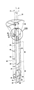
Figure 1 shows a machine 10 for making columns in
ground S in a first embodiment of the invention.
The drilling machine 10 comprises a carrier 12
having a drilling mast 14 mounted thereon, generally in
hinged manner. The carrier 12 may also have other pieces
of equipment mounted thereon such as the control desk for
the drilling machine 10.
A movable carriage 16 is mounted to slide along the
mast 14. This sliding carriage 16 can be moved along the
mast 14 by means that are themselves known and not
described in detail herein.
A rotary drive device (first rotary drive device) in
the form of a rotation head 18 is mounted on the carriage
16. The rotation head 18 is connected to the top end of
a perforation tool 20 that it is adapted to set into
rotation in order to perforate the ground S.
Below, a bottom end 20b of the perforation tool 20
is defined as its end facing the ground when the tool is
in position ready to drill, and a top end 20a of said
tool is defined as facing towards the sky when the tool
is in the same position.
The perforation tool 20 comprises a hollow central
core 22 extending along a longitudinal axis X parallel to
' CA 02906244 2015-09-25
11
the mast 14 and defining a longitudinal pipe, together
with a cutter tool 26 at its bottom end, for cutting the
ground S.
In the particular example shown, the perforation
tool 20 is an auger, and more particularly a displacement
auger, suitable for penetrating into the ground without
extracting spoil. Nevertheless, this example is not
limiting.
The operation of a displacement auger is itself well
known, and is therefore not described in detail below.
It is merely recalled here that the perforation tool
has a helical blade 24 of substantially constant
diameter extending over a bottom portion 30 of the
central core 22 (see in particular Figure 3A). In the
15 example, the bottom portion 30 is surmounted by a top
portion 32 of larger diameter for the purpose, during
drilling, of displacing laterally the soil that has been
cut by the helical blade 24.
The top end 20a of the perforation tool 20 is
20 connected to feed means 34 for feeding a first building
material, specifically concrete.
The bottom end 20b of the perforation tool 20 is
provided with an orifice 28 for injecting the first
building material into the ground S.
According to the invention, the machine 10 also has
a body 40 that extends around the perforation tool 20 and
that forms a tank in this example.
As can be seen more particularly in Figures 2 and 3,
the body 40 comprises a cylindrical outer shell 42 for
coming into contact with the ground S and extending
around the perforation tool 20.
The outer shell 42 of the body 40 is coaxial around
the perforation tool 20, and on its outside face it
carries a helical blade 44 in order to facilitate
penetration of the body 40 into the ground on rotating.
,
CA 02906244 2015-09-25
12
The diameter of the outer shell 42 is generally at
least 1.2 times greater than the diameter of the
perforation tool 20.
By way of example, the diameter of the outer shell
is 600 millimeters (mm) for a perforation tool having a
diameter equal to 420 mm.
In the example, the body 40 is for receiving a
second building material, and for this purpose it has an
inside wall 46 in the form of a tube arranged inside the
outer shell 42 and co-operating therewith to define an
annular space 48 that is to receive said second material,
specifically ballast. It can be understood that the
annular space 48 extends radially between the inner tube
46 and the outer shell 42.
At its bottom end, the body 40 has at least one
opening 50 (specifically two openings) for discharging
the second building material.
In the example, the bottom end of the body also has
at least one flap 52 (specifically two flaps) of a
dimension suitable for covering the opening 50 of the
body. In other words, each flap 52 is for closing an
opening 50.
Specifically, each flap 52 is mounted to pivot about
an axis 54 mounted on the outer shell 42. In the
example, each flap is configured to close while the body
40 is moving downwards as a result of the flap bearing
against the ground, and to open under gravity while
moving upwards under the effect of thrust from the second
material that is discharged through the corresponding
opening 50.
In the example shown, the top end of the outer shell
42 is also secured to a funnel-forming portion 56 that
makes it easier to fill the body 40 with the second
building material.
In the example shown, the body 40 is moved
exclusively by means of the perforation tool 20. The
CA 02906244 2015-09-25
13
body 40 is not mounted on the mast 14 of the machine 10.
It is independent of the mast 14.
The machine 10 has a coupling system 60 for coupling
the body 40 to the perforation tool 20, both in rotation
and in translation. These coupling means 60 operate in a
manner that can be understood better with reference to
Figures 3A and 35, and specifically they comprise at
least one first element fastened to or forming an
integral portion of the perforation tool 20 and at least
one second element fastened to or forming an integral
portion of the body 40, said elements being adapted to
co-operate so as to form a bayonet connection.
In the example, the first element is a stud 62
formed at the periphery of the central core 22. More
particularly, the perforation tool 20 presents two
diametrically opposite studs in this example.
The second element is an L-shaped slot 64 formed in
a top portion of the body 40, having a first branch 66
that is open at its bottom end and that extends in the
longitudinal direction, and another branch 68 forming a
housing extending orthogonally relative to the first
branch 66, in the direction Fl of rotation of the body
40. More particularly, in this example the body has two
diametrically opposite slots 64.
It should be observed that the coupling means 60
could also have some other form. In particular, in a
variant the at least one first element could be a slot
and the at least one second element could be a stud.
In the example shown, it can readily be understood
that in a first position (a coupled position), in which
each stud 62 comes into abutment against the end wall 68c
of a housing 68 (the stud shown in dashed lines in
Figure 35), the perforation tool 20 drives the body 40 to
move together therewith when it is set into rotation
about its axis X in the direction Fl.
Simultaneously, when the perforation tool moves
downstream, i.e. towards the ground, each stud 62 comes
CA 02906244 2015-09-25
14
into abutment against the upstream wall 68b of the
housing 68. Consequently, the perforation tool 20 drives
the body 40 in its movement in translation.
Conversely, in a second position (decoupled
position) in which each stud 62 is extracted from the
housing 68 (stud drawn in continuous lines in Figure 3B),
the central core 22 is entirely free to slide through the
body 40 and is free to rotate relative to the body 40.
As described in greater detail below, it can then be
lowered into the ground S down to the depth P2 that is
desired for the column, and then raised up to the body
while discharging the first building material through its
orifice 28.
In the example, it should be observed that the slots
64 are formed in a top portion of the body 40 that is
configured in such a manner that, regardless of the
angular position of the central core 20 relative to the
body 40, the studs 62 come into abutment against said
portion when they are in their highest position. It can
thus be understood that the perforation tool 20 always
entrains the body 40 in its upward movement along the
axis X, the studs coming into abutment against the body
40.
The top portion in question in this example is a top
portion of the inner tube 46, of smaller inside diameter.
It should be observed that in that above-mentioned
upward movement, it is desired to stop concrete being
discharged once the bottom end 20b of the tool has come
into contact with the bottom end 40b of the body 40.
For this purpose, and as shown in greater detail in
Figures 4 and 5, a shutter 70 is pivotally mounted at the
bottom end 20b of the perforation tool 20 to pivot about
a pivot axis 74. More precisely, the shutter 70 presents
an abutment surface 72 that is suitable, when the
perforation tool 20 is raised to the proximity of the
body 40, for co-operating with the bottom end of the
inner tube 46 by a camming mechanism so as to cause the
' CA 02906244 2015-09-25
,
shutter 70 to pivot about the axis 74, thereby causing
the shutter to shut the orifice 28. This stops the flow
of concrete.
With reference to Figures 6(a) to 6(e), there
5 follows a description of an example of a method of making
a hybrid column C in ground S by means of the invention
using the above-described machine 10.
In step (a), the carriage 16 is positioned at the
top of the mast 14 so that the body 40 and the
10 perforation tool 20 that are coupled together are located
above the ground.
In step (b), the rotation head 18 is actuated and
the carriage 16 is moved towards the bottom end of the
mast 14 so that the body 40 and the perforation tool 20
15 penetrate into the ground S to a first predetermined
depth Pl. The body 40 and the perforation tool 20 are
driven together in rotation in the direction of arrow Fl.
In step (c), the perforation tool 20 is turned in
the opposite direction through a few degrees, so as to
20 extract the lug 62 from the housing 68 and bring it into
register with the second branch 66 of the slot 64. The
body 40 remains in place, in particular it does not turn,
as a result of the friction of the ground S against its
outer shell 42. The body 40 and the perforation tool 20
25 are then in their decoupled position.
The carriage 16 is then moved along the mast 14
towards its bottom end 14b, causing the perforation tool
40 to move down into the ground S to a second depth P2
that is deeper than the first depth Pl.
30 In step (d), the carriage 16 is returned towards the
top end 14a of the mast 14 so as to raise the perforation
tool 20. While it is moving upwards, the shutter 70 is
open and concrete B is introduced into the ground through
the orifice 28, thereby forming a bottom column portion
35 Cl. In this step, the body 40 is held in the ground at
the first depth P1 and it does not move. As mentioned
above, the shutter 70 closes when the perforation tool 20
CA 02906244 2015-09-25
4
16
is raised up to said first depth Pl. At that instant,
the perforation tool 20 is turned in the direction of
rotation through a few degrees so that the stud 62
penetrates into the slot 64 and ends up being received in
5 the housing 68. The perforation tool 20 and the body 40
are then constrained to move together in rotation and in
translation.
In step (e), the perforation tool 20 is raised while
being driven in rotation. As the body 40 moves upwards,
10 ballast M is discharged into the ground through the
opening 50 of the body, above the bottom column portion
Cl, so as to form a top column portion C2.
It should be observed that in the example shown, the
entire volume occupied by the body 40 is filled with the
15 second building material, but that it is equally possible
to fill only a portion thereof. Under such
circumstances, it can be understood that the top surface
of the second column is situated below the surface of the
ground.
20 It should also be observed that the top portion of
the column may be constituted by a plurality of different
materials. For example, it may comprise a first segment
made of ballast and a second segment, above the first,
made of a material of poorer quality.
25 In the example, at the end of step (e), a hybrid
column C is obtained as shown in Figure 8 that is
constituted by a bottom portion Cl made of concrete B,
and a top portion C2 made of ballast M.
The machine 10 of the invention also makes it
30 possible to make columns out of a single material. For
this purpose, during step (d), the perforation tool 20 is
raised by pumping the second building material,
specifically concrete, into the ground S so as to form
the bottom portion Cl of the column. The concrete may be
35 conveyed via the longitudinal pipe and discharged via the
orifice 28 situated at the bottom end 20b of the
perforation tool 20.
CA 02906244 2015-09-25
17
Thereafter, during step (e), the assembly
constituted by the body 40 and the perforation tool 20 is
raised completely, while continuing to pump concrete into
the ground S so as to form the top portion 02 of the
column. In this implementation, it can be understood
that the top and bottom portions are both made of
concrete, which is introduced into the ground in a single
stage. Once more, the concrete may be conveyed by the
longitudinal pipe and then discharged by the orifice 28.
In this particular utilization, it can be understood that
the body 40 need not have a discharge opening 50. Under
such circumstances, provision may be made for the shutter
70 to remain open so as to allow concrete to be pumped
during this stage of upward movement. For this purpose,
the bottom end of the perforation tool projects a little
beyond the bottom end of the body so as to avoid closing
the shutter.
In a particular provision, the inner wall 46 could
also be omitted. In another implementation and on the
contrary, provision may be made for the concrete to be
conveyed via the inside of the body 40 and discharged
through the opening 50 provided at the bottom end of the
body.
In some situations, the ground to be perforated is
very compact and makes it difficult for the body 40 to
penetrate into the ground S, in particular when the body
40 is of large diameter and when the first depth P1 is
deep.
Under such circumstances, a solution using the
invention may consist in performing a prior step of
decompressing the ground S before causing the coupled-
together assembly of the body 40 and the perforation tool
20 to penetrate therein as described with reference to
step (a) above, and then to continue by performing steps
(b) to (e).
This prior decompression step, shown in Figure 7,
consists in lowering the perforation tool 20 into the
CA 02906244 2015-09-25
18
ground on its own, generally at least as far as the first
depth P1, i.e. lowering the perforation tool 20 while it
is separate from the body 40 (leaving the body resting on
the surface of the ground), and then in raising the tool
and in coupling together the body 40 and the perforation
tool 20.
Figures 9A and 9B show a machine 110 in a second
embodiment of the invention that is particularly adapted
to making two-diameter piles.
It should be observed that elements that are
identical or similar to elements of the machine 10 in the
first embodiment are given the same numerical references
plus 100.
This machine 110 has a longitudinal mast 114 mounted
on a carrier 112, and a carriage 116 that slidable along
the mast 114, similar to the carriage 16 in the first
embodiment, the carriage having a first rotary drive
system 118 mounted thereon for driving a perforation tool
120 in rotation.
The machine 110 also has a body 140 similar to the
body 40 of the first embodiment. Nevertheless, it should
be observed that in this example the body is longer than
when making a structure with a low top level. In this
example, the body presents a length of about 6 meters
(m).
A coupling system 160 between the body 140 and the
perforation tool 120 is also provided, which system is
similar to that of the first embodiment.
The machine 110 in this second embodiment differs
from the preceding machine in that it also has a second
carriage 180 mounted to slide along the mast 114, below
the first carriage 116.
In the example shown, this second carriage 180
carries a second rotary drive system 182, which is
coupled to the body 140.
In this example, the second rotary drive system 182
comprises a ring 184 connected to the outer shell 142 of
CA 02906244 2015-09-25
19
the body 140, e.g. by being welded to its outside
surface. The ring is itself connected to a motor 186 for
driving it in rotation.
With the body 140 being driven in rotation by the
perforation tool 120, the carriage 180 is free to move in
translation along the mast 114 while being entrained by
the body 140. No specific drive means are provided for
moving the second carriage 180 on the machine 110.
It can be understood that the second rotary drive
system 182 is for acting in addition to the perforation
tool 120, which serves to drive it in rotation when
coupled to the body 140. The rotary torque applied to
the body 140 during the stage of drilling into the ground
is thus increased, thereby making drilling easier, in
particular when the body 140 is of large diameter, when
the first depth P1 is particularly deep, and/or when the
ground is particularly compact.
With reference to Figures 10(a) to 10(e), there
follows a description of the method of the invention for
making a two-diameter pile using the second embodiment
machine 110 shown in Figures 9A and 93.
In step (a), the first carriage 116 is located at
the top end of the mast 114. The perforation tool 120
and the body 140 are in a high position, above the ground
S, and they are coupled together.
In step (b), the perforation tool 120 is driven in
rotation and the carriage 116 is lowered towards the
bottom end of the mast 114, entraining the assembly
constituted by the coupled-together perforation tool 120
and the body 140, and also entraining the second carriage
180 that is secured to the body 140. At the same time,
the second rotary head 182 drives the body 140 in
rotation in the same direction as the perforation tool
120.
The assembly constituted by the body 140 and the
perforation tool 120 is lowered to the first depth Pl.
* CA 02906244 2015-09-25
In step (c), the perforation tool 120 and the body
140 are uncoupled and the perforation tool 120 is lowered
into the ground S down to the second depth P2, deeper
than the first depth Pl.
5 In step (d), the perforation tool 120 is raised up
to the depth Pl, while injecting concrete B into the
ground, thereby forming a bottom portion of a pile, and
then the perforation tool 120 and the body 140 are
coupled together (both in rotation and in translation).
10 In step (e), the assembly formed by the perforation
tool 120 and the body 140 is raised finally while
continuing to inject concrete B via the orifice 128 of
the perforation tool, so as to form the top portion of
the pile.
15 Optionally, in an additional step (f), and before
the concrete has set, it is possible to introduce at
least one reinforcing cage 190 into the first and/or
second column portion in order to reinforce the pile. By
way of example, it is possible to place a first
20 reinforcement cage presenting a first diameter in the
first portion of the column, and a second reinforcement
cage of greater diameter in the second portion of the
column. Under such circumstances, the second
reinforcement cage may optionally surround a top portion
of the first reinforcement cage. It is also possible to
place a single reinforcement cage of varying diameter in
both the first and second column portions.
Once the concrete has set, a two-diameter concrete
pile C is finally obtained as shown in Figure 11, which
pile presents a bottom portion Cl' and a top portion C2'
of greater diameter, both portions being reinforced by
metal reinforcement.
It can be understood that in this second embodiment,
the openings 50 and the flaps 52 may be omitted from the
body. Under such circumstances, provision is also made
for the shutter 70 to remain open by allowing the bottom
CA 02906244 2015-09-25
21
end of the perforation tool to project a little outside
the body.
Nevertheless, it should be observed that the machine
in this second embodiment may be used in the same manner
for making hybrid columns, and in particular for making
concrete structures of low top level, which structures
are covered in temporary filling material, as described
with reference to the first embodiment.