Note: Descriptions are shown in the official language in which they were submitted.
CA 02906387 2015-09-14
WO 2014/150041
PCT/US2014/021965
LABOR MANAGEMENT DEVICES FOR DECREASING THE INCIDENCE
OF CESAREAN CHILDBIRTH
INCORPORATION BY REFERENCE
United States Patent Application Number 11/197,627 filed August 5, 2005, and
published as Patent Application Publication No. 2007/0031466, titled Method,
Apparatus and
System for Preventing or Reducing the Severity of Hemorrhoids commonly
assigned to the
present applicant is hereby incorporated by reference in its entirety.
United States Patent Application Number 11/743,858 filed August May 3, 2007,
issued as Patent No. 7,673,633 entitled Apparatus and Method of Inhibiting
Perianal Tissue
Damage commonly assigned to the present applicant is hereby incorporated by
reference in
its entirety.
United States Patent Application Number 12/106,956 filed August April 21,
2008,
and published as Patent Application Publication No. 2008/0202505 entitled
Apparatus and
Method of Supporting Patient Tissue, commonly assigned to the present
applicant is hereby
incorporated by reference in its entirety.
BACKGROUND
The use of epidurals and pain relieving drugs during the labor and delivery
process
can desensitize the birthing mother from experiencing the natural body signals
needed to
push the baby through the birth canal and thereby ultimately delay the
progression of
childbirth. One indication of this phenomenon is that in modern times, there
has been a
dramatic increase in the incidence of children born by Cesarean childbirth.
This form of
child birth significantly increases the cost to the healthcare system when
compared to a
natural vaginal delivery. In addition, the birthing mother needs significantly
more time to
recover from a Cesarean operation compared to a natural vaginal child
delivery.
While prior apparatus and methods like those disclosed in U.S. Patent
Application
Publications 2007/0031466 and U.S. Patent No. 7,673,633 provide stable support
for the soft
perianal tissues near the anal orifice, these can be further improved to
provide additional
benefits for labor management to decrease the incidence of Cesarean
childbirth. More
specifically, there are no currently available devices and methods that permit
a healthcare
provider to actively manage the labor and birthing process to promote a higher
incidence of
1
CA 02906387 2015-09-14
WO 2014/150041
PCT/US2014/021965
vaginal births and, if desired in certain situations, manage the labor process
to avoid potential
lifelong damage to the mother such as pelvic floor injuries and anal sphincter
damage.
Thus, there is a need for devices and methods permitting the management of the
child
birthing process to encourage vaginal child birth to reduce the incidence of
Cesarean
childbirths.
SUMMARY
In one aspect, the present disclosure provides a method of decreasing the
incidence of
Cesarean childbirth by managing the labor process. In one aspect, a tactile
feedback device is
positioned adjacent the perianal tissues. A mother's labor is monitored for
the progression of
the baby along the birth canal. If the monitoring determines that the birthing
process is not
progressing as desired, the sensation offered by the tactile feedback device
can be increased.
In one aspect, the tactile feedback device is a pressure inducing device. In
one aspect, the
pressure inducing device is applied to the perianal tissue with a first
pressure and then after
monitoring the mother's condition, the device is repositioned to provide a
second pressure on
the perianal tissues. In one aspect, the second pressure is greater than the
first pressure. In a
further aspect, the device includes a pressure indicator and the method
includes monitoring
the relative pressure applied to the perianal tissue.
In still a further feature of the present disclosure, a method is provided
that reduces
the duration of second stage labor and delivery by allowing a healthcare
provider to monitor
and guide the labor process. The method includes applying a tactile feedback
device in
engagement with the perianal tissue and monitoring the progression of labor
during the
second stage. If second stage labor deviates from a predetermined time and
position progress
estimation, the tactile feedback device is adjusted. If the mother is below
the predetermined
time and position progress estimation, in one embodiment, the amount of
tactile feedback is
increased. In one feature, the tactile feedback device is a pressure inducing
device and tactile
feedback is increased by increasing the relative amount of pressure on the
perianal tissue by
increasing the pressure from a first initial engagement to a second higher
pressure perianal
tissue engagement. Such a method allows the healthcare provider to monitor the
effectiveness of a mother's contractions via the impact on the perianal
tissues while also
providing both the healthcare provider and mother with a feedback mechanism to
have a
reference for turning unsuccessful contractions into effective pushes that
tend to move the
2
CA 02906387 2015-09-14
WO 2014/150041
PCT/US2014/021965
baby down the birth canal. In this manner, the present system and method allow
cooperation
between the patient and healthcare provider to allow the labor and delivery
process to be
managed to more quickly achieve a vaginal delivery and obviate the need for
Cesarean
section delivery techniques.
In yet a further feature of the present disclosure, a method is provided to
inhibit the
evulsion or protrusion of soft tissue adjacent the anus. The method includes
positioning a
blocking element adjacent the perianal tissues. The blocking element is
configured to inhibit
the evulsion or protrusion of soft tissue adjacent the anus. In one feature,
the blocking
element is initially spaced slightly from the perianal tissue such that some
outward movement
of the perianal tissue is permitted but upon engagement with the blocking
element further
outward movement by the tissue is inhibited. This engagement can increase the
tactile
feedback to the mother by providing a change in tactile sensation upon
engagement with the
blocking element. In an alternative feature, the blocking element is initially
positioned in
contact with the perianal tissue without providing significant pressure on the
perianal tissues
such that the location of the tissues are maintained but not compressed inward
toward the
anus of the patient. One aspect of the method allows a healthcare provider to
monitor, via the
blocking element, the amount of pressure applied to the blocking element by
engagement
with the blocking element during contractions or pushes during the birthing
process.
In still a further feature of the present disclosure, a method is provided to
protect a
mother from pelvic floor injuries and anal sphincter damage. In one aspect,
the method
includes applying a blocking member adjacent the perianal tissue to inhibit
evulsion or
protrusion of the soft tissue. In one form, the blocking member is applied
adjacent the
perianal tissues in an initial non-pressure inducing engagement. The blocking
member can
include a pressure detection feature and the healthcare provider can monitor
the pressure
detector during pushing and contractions of the patient to evaluate the amount
of pressure
applied to the perianal tissue. If the pressure is above an upper threshold,
the patient will be
encouraged to reduce the extent of their efforts at pushing during
contractions. However, if
the pressure detection indicates a pressure below a lower threshold, the
healthcare provider
will encourage the patient to apply more downward pressure during contracts to
more
effectively push the baby down the birth canal toward the vaginal opening. In
this manner,
the healthcare provider can manage the mother's labor to maintain the pressure
on the
perianal tissues within a desired range that is safe for the mother's tissue
while at the same
3
CA 02906387 2015-09-14
WO 2014/150041
PCT/US2014/021965
time encouraging proficient pushing from the mother to advance the labor and
delivery
process to avoid stalled delivery and encourage fetal decent to achieve a
vaginal child birth.
In still a further feature, a method is provided for managing the birthing
process. In
an initial phase, it is determined whether the mother has previously had a
successful vaginal
delivery. If yes, then the mother is allowed to continue with unaided labor.
Even for this
mother, labor is continually monitored and if the progression of labor slows,
then a tactile
feedback device may be applied to the perianal tissue and the method continues
as set forth
below. If the mother has not previously had a successful vaginal delivery,
this could include
first time nulliparous mothers or women attempting vaginal births after
Cesarean deliveries, a
tactile feedback device is applied to the perianal tissue. In one form, the
tactile feedback
device is applied in a pressure engagement position such that the perianal
tissue is displaced
inwardly and a first pressure is applied. In an alternative form, the tactile
feedback device is
positioned adjacent the perianal tissue without pressure such that the
perianal tissue is not
displaced inwardly. The mother may then be allowed to continue with an aided
or managed
labor process. In a further feature, the managed labor process continues with
a healthcare
provider receiving feedback from the device to evaluate the effectiveness of
the mother's
pushing efforts during contractions. If the feedback device indicates pushes
above a first,
minimum threshold, the mother may continue her labor efforts without change.
If the
feedback device indicates pushes below the first, minimum threshold, the
healthcare provide
will instruct the patient on techniques to channel contraction efforts into
effective pushes
urging the baby downward along the birth canal. If the patient continues to
struggle to
achieve effective pushes and labor is not progressing, then the healthcare
provider may
increase the pressure applied by the tactile feedback device on the perianal
tissues to provide
the mother with even greater tactile feedback. In one aspect, if the mother
receives an
epidural or other pain relieving medication, then the healthcare provide would
responsively
increase the pressure applied by the tactile feedback device on the perianal
tissue in an effort
to overcome the effects of the numbing treatment given to the mother. In still
a further
alternative aspect of actively managing the labor process, the healthcare
provider also
monitors the feedback device for pressures above a maximum pressure
indication. Such high
pressures may be indicators for pelvic floor injuries and anal sphincter
damage. Thus, the
healthcare provider may instruct the patient to reduce the pushing
effectiveness during
contractions to limit the pressure on the mother's delicate tissues in an
effort to inhibit
4
CA 02906387 2015-09-14
WO 2014/150041
PCT/US2014/021965
damage to these tissues. In an alternative feature of the present method, the
healthcare
provider monitors pressure applied by the tactile feedback device to maintain
the pressure
during contractions between the first, minimum pressure and the higher,
maximum pressure
to thereby balance the needs of progressing labor while simultaneously
attempting to avoid
lifelong injuries to the mother.
In an exemplary aspect, the present disclosure is directed to an apparatus
including a
perianal support member that has a pressure surface configured for engagement
with tissue
adjacent an anal orifice. A pressure detecting system may be associated with
the perianal
support member to detect pressure indicative of pressure on the tissue
adjacent the anal
orifice of a patient.
In an exemplary aspect, the present disclosure is directed to a method
including
applying a perianal support device to a perianal region of a patient;
monitoring pressure in the
perianal region with a feedback device associated with the perianal support
device; advancing
the perianal support device against the perianal region until the monitored
pressure meets a
first pressure threshold based on the feedback device; and securing the
perianal support
device in a position where the monitored pressure meets the first pressure
threshold. In a
further feature, the method includes monitoring the progression of labor and
adjusting the
pressure applied by the perianal support device in response to changes in the
progression of
labor, including failure of the baby to progress within the birth canal or
failure of the
mother's pushes to generate a sufficient change in pressure indicated by the
pressure monitor.
In one aspect, the pressure applied to the perianal tissue is increased if the
progression of
labor in slowed below a predetermined threshold allowing a healthcare provider
to manage
the progression of labor.
In an aspect, the method further includes utilizing the feedback device to
monitor
sensed pressure changes associated with contractions and alerting a user to
the pressure
changes. In some aspects, alerting a user includes one of activating an
audible alert,
activating a visual alert, and activating a material change. In some aspects,
activating a visual
alert includes turning a light on, off, or changing its color.
In an aspect, the method further includes alerting a user when the monitored
pressure
exceeds a second pressure threshold higher than the first pressure threshold.
5
CA 02906387 2015-09-14
WO 2014/150041
PCT/US2014/021965
In an aspect, the pressure detecting system comprises a strain gauge disposed
on a
wall portion of the perianal support member. In an aspect, the pressure
detecting system
comprises: a pressure detecting element configured to detect pressure applied
on the tissue by
the perianal support member; and a user interface configured to display
information relating
to the pressure detected by the pressure detecting element. In an aspect, the
user interface is
configured to wirelessly communicate with the pressure detecting element. In
an aspect, the
pressure detecting system comprises a compliant pad on a pressure surface of
the perianal
support member. In an aspect, wherein the compliant pad is configured to
change appearance
when pressure exceeds a threshold pressure. In an aspect, the perianal support
member is at
least partially transparent.
In a further aspect, the pressure detecting system comprises: a pressure
detector; and a
light associated with the pressure detector and configured to turn on when the
pressure
detector detects application of a therapeutic pressure on the perianal tissue.
In an aspect, the
pressure detector comprises a pressure switch. In an aspect, the pressure
switch is configured
to complete a circuit when a therapeutic pressure is applied to the perianal
tissue. In an
aspect, the pressure detecting system comprises: a transmitter carried on the
perianal support
member; and a receiver spaced apart from the perianal support member
configured to receive
signals from the transmitter indicative of pressure applied by the perianal
support member on
the perianal tissue. In an aspect, the pressure detecting system comprises a
securing member
extending from the perianal support member, the securing member being
configured to
convey information indicative of pressure applied on the perianal tissue by
the perianal
support member. In an aspect, the securing member comprises an element
configured to
change appearance when pressure changes. In an aspect, the securing member is
associated
with a visual indicator such as an LED indicator. In an aspect, the securing
member
comprises an elastically stretchable portion and at least one stretch
inhibitor configured to
inhibit stretch when stretching is sufficient to apply a therapeutic pressure
on the perianal
tissue. In an aspect, the at least one stretch inhibitor is a substantially
inelastic fiber. In an
aspect, the at least one stretch inhibitor is a substantially inelastic strap.
In an aspect, the
securing member comprises a geometric figure that takes shape when stretching
is sufficient
to apply a therapeutic pressure on the perianal tissue. In an aspect, the
securing member
comprises a strain gauge configured to measure strain as an indicator of a
therapeutic
pressure on the perianal tissue.
6
CA 02906387 2015-09-14
WO 2014/150041
PCT/US2014/021965
In yet another aspect, the apparatus includes a device adjustment element
graspable
by the patient when the perianal support member is engaged with the tissue. In
an aspect, the
device adjustment element comprises handle portions. In an aspect, the device
adjustment
element comprises: an adjustment strap extending from the perianal support
member; and an
anchor pad comprising a guide configured to guide movement of the adjustment
strap. In an
aspect, the apparatus includes a compliant pad, the pressure detecting system
being disposed
between the complaint pad and the perianal support member. In an aspect, the
apparatus
includes a compliant pad having a pocket formed therein, the pressure
detecting system being
disposed within the pocket. In an aspect, the perianal support member includes
a cooling
applicator configured to apply therapeutic cooling to the perianal tissue. In
an aspect, the
cooling applicator comprises a receptacle for a cooling material. In an
aspect, the perianal
support member is a thermal conductor. In an aspect, the cooling applicator is
shaped to fit
flush with the perianal support member. In an aspect, the pressure detecting
system is
configured to count contractions during child delivery.
In an exemplary aspect, the present disclosure is directed to an apparatus
including a
perianal support member having a pressure surface configured for engagement
with tissue
adjacent an anal orifice. A cooling applicator is configured to apply
therapeutic cooling to
the perianal tissue.
In an exemplary aspect, the cooling applicator comprises an ice pack. In an
aspect,
the cooling applicator comprises a receptacle for a cooling material. In an
aspect, the
perianal support device is a thermal conductor. In an aspect, the cooling
applicator is shaped
to fit flush with the perianal support member. In an aspect, the apparatus
includes a pressure
detecting system associated with the perianal support member to detect
pressure indicative of
pressure on the tissue adjacent the anal orifice of a patient. In an aspect,
the pressure
detecting system comprises a strain gauge disposed on a wall portion of the
perianal support
member. In an aspect, the pressure detecting system comprises: a pressure
detecting element
configured to detect pressure applied on the tissue by the perianal support
member; and a user
interface configured to display information relating to the pressure detected
by the pressure
detecting element. In an aspect, the user interface is configured to
wirelessly communicate
with the pressure detecting element.
7
CA 02906387 2015-09-14
WO 2014/150041
PCT/US2014/021965
In an aspect, the pressure detecting system comprises a securing member
extending
from the perianal support member, the securing member being configured to
convey
information indicative of pressure applied on the perianal tissue by the
perianal support
member. In an aspect, a device adjustment element graspable by the patient
when the
perianal support member is engaged with the tissue. In an aspect, the device
adjustment
element comprises handle portions.
In an exemplary aspect, the present disclosure is directed to an apparatus,
including a
perianal support member including a pressure surface configured for engagement
with tissue
adjacent an anal orifice. A device adjustment element is graspable by the
patient when the
perianal support member is engaged with the tissue.
In an aspect, the device adjustment element comprises handle portions. In an
aspect,
the device adjustment element comprises: an adjustment strap extending from
the perianal
support member; and an anchor pad comprising a guide configured to guide
movement of the
adjustment strap. In an aspect, the perianal support member includes a cooling
applicator
configured to apply therapeutic cooling to the perianal tissue. In an aspect,
the cooling
applicator comprises an ice pack. In an aspect, the cooling applicator
comprises a receptacle
for a cooling material. In an aspect, the perianal support device is a thermal
conductor. In an
aspect, the cooling applicator is shaped to fit flush with the perianal
support member. In an
aspect, the apparatus includes a pressure detecting system associated with the
perianal
support member to detect pressure indicative of pressure on the tissue
adjacent the anal
orifice of a patient. In an aspect, the pressure detecting system comprises a
strain gauge
disposed on a wall portion of the perianal support member. In an aspect, the
pressure
detecting system comprises: a pressure detecting element configured to detect
pressure
applied on the tissue by the perianal support member; and a user interface
configured to
display information relating to the pressure detected by the pressure
detecting element. In an
aspect, the user interface is configured to wirelessly communicate with the
pressure detecting
element. In an aspect, the pressure detecting system comprises a securing
member extending
from the perianal support member, the securing member being configured to
convey
information indicative of pressure applied on the perianal tissue by the
perianal support
member.
8
CA 02906387 2015-09-14
WO 2014/150041
PCT/US2014/021965
In an exemplary aspect, the present disclosure is directed to a method,
comprising:
providing a support member having a pressure surface configured for engaging
the perianal
area of a patient and an elongated compression element; positioning the
pressure surface
proximate the perianal area of a patient and the compression member extending
outwardly
beyond the crown of the buttocks; and detecting the pressure on the perianal
area of the
patient applied by the pressure surface against the perianal area of the
patient.
In an aspect, detecting the pressure on the perianal area comprises detecting
the
pressure with a strain gauge disposed on the compression element of the
perianal support
member. In an aspect, the method includes displaying information relating to
the detected
pressure on a user interface. In an aspect, the method includes transmitting
signals from the
support member to the user interface. In an aspect, the method includes
alerting a healthcare
provider when the detected pressure detects application of a therapeutic
pressure on the
perianal tissue. In an aspect, alerting a healthcare provider comprises
changing the color of a
compliant pad. In an aspect, alerting a healthcare provider comprises turning
on a light bulb.
In an aspect, alerting a health care provider comprises inhibiting stretch of
a securing member
when stretching is sufficient to apply a therapeutic pressure on the perianal
tissue. In an
aspect, the method includes therapeutically cooling the perianal tissue with
the support
member
In an exemplary aspect, the present disclosure is directed to a method of
inhibiting
perianal tissue damage during childbirth, comprising: positioning a perianal
support device in
contact with at least a portion of the perianal tissue of the patient prior to
delivery of a child;
positioning a compression member associated with the support device to extend
outwardly in
the saggital plane beyond a gluteal cleft; adjusting pressure applied on the
perianal tissue
until a pressure detecting system indicates application of a therapeutic
pressure by the
perianal support device.
In an aspect, adjusting pressure applied comprises pulling a device adjustment
element attached to the perianal support device to increase the pressure on
the perianal tissue.
In an aspect, the method includes monitoring the pressure detecting system to
confirm the
applied pressure is above a therapeutic pressure threshold. In an aspect, the
method includes
detecting the pressure with a strain gauge disposed on the compression element
of the
perianal support member. In an aspect, the pressure detecting system displays
information
9
CA 02906387 2015-09-14
WO 2014/150041
PCT/US2014/021965
relating to the detected pressure on a user interface. In an aspect, the
method includes
therapeutically cooling the perianal tissue with the support member.
Further aspects, forms, embodiments, objects, features, benefits, and
advantages of
the present disclosure shall become apparent from the detailed drawings and
descriptions
provided herein.
BRIEF DESCRIPTION OF THE DRAWINGS
Fig. 1 is a partial cross sectional top view of a perianal support system
applied to a
patient with stylized depiction of the patient anatomy.
Fig. 2 is a partial perspective bottom view of the perianal support system
applied to a
patient during child delivery.
Fig. 3 is a perspective view of one aspect of the perianal support system
according to
an exemplary embodiment.
Fig. 4 is a perspective view of a portion of the perianal support system
according to an
exemplary embodiment.
Fig. 5 is an end view of a portion of the perianal support system of Fig. 4.
Fig. 6 is a side view of the perianal support system of Fig. 1 according to an
exemplary embodiment.
Fig. 7 is a perspective view of a portion of another perianal support system
according
to an exemplary embodiment.
Fig. 8 is an end view of a portion of the perianal support system of Fig. 7.
Fig. 9 is a side view of a portion of the perianal support system of Fig. 7.
Fig. 10 is a perspective view of a portion of another perianal support system
according to an exemplary embodiment.
Fig. 11 is an end view of a portion of the perianal support system of Fig. 10.
Fig. 12 is a side view of a portion of the perianal support system of Fig. 10.
Fig. 13 is an end view of a portion of another perianal support system
according to an
exemplary embodiment.
Fig. 14 is a side view of a portion of the perianal support system of Fig. 3.
CA 02906387 2015-09-14
WO 2014/150041
PCT/US2014/021965
Fig. 15 is a view of a portion of another perianal support system according to
an
exemplary embodiment in an un-stretched condition.
Fig. 16 is a view of the portion of the perianal support system of Fig. 15 in
a stretched
condition.
Fig. 17 is a view of a portion of another perianal support system according to
an
exemplary embodiment in an un-stretched condition.
Fig. 18 is a view of the portion of the perianal support system of Fig. 17 in
a stretched
condition.
Fig. 19 is a view of a portion of another perianal support system according to
an
exemplary embodiment in an un-stretched condition.
Fig. 20 is a view of the portion of the perianal support system of Fig. 19 in
a stretched
condition.
Fig. 21 is a view of a portion of another perianal support system according to
an
exemplary embodiment in an un-stretched condition.
Fig. 22 is a side view of the portion of the perianal support system of Fig.
21.
Fig. 23 is a view of the portion of the perianal support system of Fig. 21 in
a stretched
condition.
Fig. 24 is a side view of the portion of the perianal support system of Fig.
21 in a
stretched condition.
Fig. 25 is a view of a portion of another perianal support system according to
an
exemplary embodiment in an un-stretched condition.
Fig. 26 is a view of the portion of the perianal support system of Fig. 26 in
a stretched
condition.
Fig. 27 is a view of a portion of another perianal support system according to
an
exemplary embodiment in an un-stretched condition.
Fig. 28 is a view of the portion of the perianal support system of Fig. 17 in
a stretched
condition.
11
CA 02906387 2015-09-14
WO 2014/150041
PCT/US2014/021965
Fig. 29 is a perspective view of one aspect of the perianal support system
according to
an exemplary embodiment.
Fig. 30 is a partial perspective bottom view of the perianal support system
applied to a
patient during child delivery.
Fig. 31 is a perspective view of one aspect of the perianal support system
according to
an exemplary embodiment.
Fig. 32 is a view of a portion of another perianal support system according to
an
exemplary embodiment.
Fig. 33 is a view of a portion of another perianal support system according to
an
exemplary embodiment.
Fig. 34 is a view of a portion of another perianal support system according to
an
exemplary embodiment.
Fig. 35 is a view of a portion of another perianal support system according to
an
exemplary embodiment.
Fig. 36 is a view of a portion of another perianal support system according to
an
exemplary embodiment.
Fig. 37 illustrates a method of managing a mother's child birthing labor
according to
an exemplary embodiment.
DETAILED DESCRIPTION
For the purposes of promoting an understanding of the principles of the
present
disclosure, reference will now be made to the embodiments illustrated in the
drawings, and
specific language will be used to describe the same. It will nevertheless be
understood that
no limitation of the scope of the disclosure is intended. Any alterations and
further
modifications in the described devices, instruments, methods, and any further
application of
the principles of the disclosure as described herein are contemplated as would
normally occur
to one skilled in the art to which the disclosure relates. In particular, it
is fully contemplated
that the features, components, and/or steps described with respect to one
embodiment may be
combined with the features, components, and/or steps described with respect to
other
embodiments of the present disclosure.
12
CA 02906387 2015-09-14
WO 2014/150041
PCT/US2014/021965
The present disclosure is directed to systems, devices, and methods for
managing
child birthing labor along with supporting or treating perianal tissue of a
patient. These
systems introduce novel elements and methods that may improve the reliability,
the
predictability, and the effectiveness of labor along with supporting or
treating the perianal
tissues. In addition, some aspects of these systems include elements and
methods that may
simplify proper securing and proper placement. Some embodiments provide
feedback to
surgeons and patients regarding pressure levels due to device application or
physiological
transformations, such as those that occur during muscle contractions during
child delivery.
Supporting the perianal tissue of a patient during 2nd stage labor may reduce
the incidence of
a number of complications and conditions, including, for example, pelvic floor
incompetence
or dysfunction (over-stretching of pelvic floor muscles, ligaments and
tendons), organ
prolapse results from the over stretching, incontinence secondary to pressure
and stretching
exerted on bladder and bladder neck, over stretching due to use of forceps in
delivery,
perineum tears and lacerations due to over stretching, forceps use, or
uncontrolled
flexion/extension of the fetal head as it descends, and hemorrhoids. Still
further, application
of pressure in the perianal region can be sensed as a tactile sensation by a
patient, often even
after administration of an epidural and provides a pushing focal point to
enhance the
effectiveness of contractions and pushing. This may result in a shortening of
second stage
labor by enhancing the effectiveness of contractions in advancing the baby
down the birth
canal. In addition, it may reduce the necessity of Cesarean section deliveries
by encouraging
and monitoring via pressure feedback the effectiveness of contractions to
generate a pushing
effect on the baby moving it toward the vaginal opening. It may also cover all
or most of the
anal orifice and thereby provide defecation suppression of hemorrhoid
development and or
advancement of existing hemorrhoids. Some embodiments may include a post-
delivery
therapeutics delivery system.
In some aspects, the devices and systems disclosed herein may include varying
pressure detecting and monitoring capabilities. For simplicity, these are
referred to herein as
a) a static support pressure indication capability, b) a dynamic support
pressure indication
capability, and c) an extreme support pressure indication capability. The
static support
pressure indication capability may include detecting and monitoring pressure
ranges that
provide therapeutic support and push feedback. The dynamic support pressure
indication
capability may include detecting and monitoring pressure ranges indicative of
increases in
13
CA 02906387 2015-09-14
WO 2014/150041
PCT/US2014/021965
pressure level above the static pressure that provide feedback on push
effectiveness. The
extreme support pressure indication capability may include detecting and
monitoring pressure
ranges above desired pressures and may warrant adjusting the perianal support
device in
order to alleviate some the pressure on the patient.
Turning now to Fig. 1-3, a perianal support system 100 according to one
exemplary
embodiment disclosed herein is illustrated in association with the perianal
tissue of a patient
10. Figs. 1 and 2 shows the perianal support system 100 in use on the patient
10 and Fig. 3
shows the support system 100 independent of the patient 10.
In Fig. 1, the patient 10 is shown in partial cross section to illustrate a
portion of the
rectum 54, anal canal 36, anal orifice 38, internal venous plexus 29,
pectinate line 37 (also
known as the dentate line), and external venous plexus 28. The patient's
buttocks 14 and 15
are shown with the crown of the buttocks 16 and 17, respectively, laterally
adjacent the
perianal region 26. The gluteal cleft 13 (Fig. 2) is between buttocks 14 and
15. The buttocks
14 and 15 extend laterally beyond crowns 16 and 17 toward lateral flanks 18
and 19,
respectively. The crowns 16 and 17 of each buttocks 14 and 15 in essence
define the midline
of each leg and the lateral flanks 18 and 19 are the area lateral of the
leg/buttocks midline.
The lateral flanks 18 and 19 may include, for example but without limitation,
all or a portion
of the lateral buttocks, hips, or upper thigh of the patient.
Fig. 2 illustrates the patient 10 during a child birthing process.
Contractions during
labor move a child 12 into the birth canal and ultimately, for a vaginal
delivery, through the
vaginal opening 11, as shown in Fig. 2. In an alternative birthing process,
labor is
commenced to move the child 12, but for a variety of reasons, the delivery
does not occur
vaginally but instead caesarian delivery is performed through a surgical
opening in the
mother's abdomen. During the birthing process, tremendous pressure is exerted
in an effort
to move the child toward delivery. At least some of this pressure is exerted
against the
tissues adjacent the anal orifice 38 in the perianal region 26 (Fig. 1). The
result of these
forces is that blood vessels near the anus, such as those in the external
venous plexus 28, may
bulge or rupture causing hemorrhoids or increasing their severity. Still
further, other tissues
in the perianal region 26 adjacent the anus may distend outwardly opposite
arrow Al in Fig.
1 causing lacerations such as tearing around the vaginal opening 11 or
fissures from the anus.
14
CA 02906387 2015-09-14
WO 2014/150041
PCT/US2014/021965
In addition to the blood loss, pain, and discomfort, these lacerations can be
a location for
infections in the mother.
The systems, devices, and methods disclosed herein, including the exemplary
system
100, are shaped and structured to not only support the perianal tissues
(tissue forming or
supporting the perianal region 26) during the birthing process without
interfering with the
birthing canal or vaginal opening 11, but also include features, elements, or
structure that
simplify application to the patient by providing indicators that detect
pressure or indicate
when desired application pressures are achieved. Some exemplary embodiments
provide
feedback to surgeons and patients regarding pressure levels due to device
application or
physiological transformations, such as those that occur during muscle
contractions during
child delivery. Additional exemplary embodiments provide user adjustment
systems and
techniques, allowing a patient as well as a doctor to adjust the devices for
comfort and
effectiveness. Accordingly, the exemplary systems, devices, and methods
disclosed herein
support the perianal tissue to inhibit damage to the tissue near the anal
orifice 38, both
internally and externally, to inhibit, for example but without limitation, the
formation or
advancement of external hemorrhoids, and/or to inhibit the formation or
advancement of
lacerations of the perianal tissues.
Fig. 3 shows the support system 100 independent of the patient. The support
system
100 includes a perianal support member 102 having an external pressure surface
104 and a
pair of extending securing members 106, 107 attached to and configured to
assist in holding
the perianal support member 102 in pressurized engagement with the perianal
tissue in the
perianal region 26 shown in Figs. 1 and 2. The external pressure surface 104
extends along
midline axis 108 between a posterior edge 110 and the anterior edge 112 of the
perianal
support member.
The perianal support member 102 includes a pair of compression elements 116,
124
formed as flanges. The first compression element 116 has a distal end portion
118 adjacent
the pressure surface 104 and an opposing proximal end portion 120. The
opposing second
compression element 124 has a distal end portion 126 adjacent the pressure
surface 104 and
an opposing proximal end portion 128. The perianal support member 102 includes
an outer
surface 130 and an opposing inner surface 132 (Figs. 1 and 2) defining an
access cavity 136.
CA 02906387 2015-09-14
WO 2014/150041
PCT/US2014/021965
As shown in Figs. 1-3, the securing member 106 is attached to the first
compression
element 116 adjacent its proximal end portion 120. In a similar manner, the
second securing
member 107 is attached to the second compression member 118 adjacent its
proximal end
portion 128. In the illustrated embodiment, the securing members 106, 107 are
elongated,
flexible strips of a material. Midline end portions 140, 142 of the securing
members 106, 107
attach to the compression elements 116, 118 of the perianal support member 102
while
opposing lateral ends 144, 146 extend outwardly laterally from the midline or
contact axis
108 of the perianal support system 100.
The first securing member 106 forms all or a part of a securing mechanism 180.
In
the embodiment in Figs. 1-3, the securing mechanism 180 includes the securing
member 106
and an associated anchor pad 182. In this example, the securing member 106
includes a first
half of a releasable fastening system on a surface 183, such as a hook and
loop system or a
releasable adhesive system. In the illustrated embodiment, the anchor pad 182
has a
generally square shape that is shorter in length and wider than elongated
securing member
106. The shape of the anchor pad is shown for illustration purposes and may
take any form
that is suitable for fixing to a patient or inanimate object, as well as
joining to the elongated
fixation member. The anchor pad 182 includes a first surface 184 having an
adhesive surface
adapted for joining to the patient's skin or some inanimate object. The
opposing surface 185
includes the second half of the releasable fastening system. In a similar
manner, the securing
member 107 forms all or part of a securing mechanism 186 and includes a
releasable
fastening system on surface 187, such as a hook and loop system or a
releasable adhesive
system. In this example, a second component of the securing mechanism 186
includes an
anchor pad 188. In the illustrated embodiment, anchor pad 188 has a generally
rectangular
shape that is shorter in length and wider than elongated fixation member 107.
The anchor
pad 188 includes a first surface 189 having an adhesive surface adapted for
joining to the
patient's skin or some inanimate object. The opposing surface 190 includes the
second half of
the releasable fastening system.
In some embodiments, instead of using the hook and loop fastener arrangement
discussed above, at least a portion of a surfaces 183, 187 of the securing
members 106, 107
has an adhesive coating adapted for joining to a fixed object. The securing
member 106 may
be fixed to the inner surface 132 of the compression element 116. Likewise,
the securing
member 107 is joined to the proximal end portion 128 of the second compression
element
16
CA 02906387 2015-09-14
WO 2014/150041
PCT/US2014/021965
124. At least a portion of a surface of the securing member includes an
adhesive coating that
can fix the securing member to another object. In one embodiment, the adhesive
coating is
adapted for releasably adhering to a patient's skin. In another embodiment,
the adhesive is
adapted for joining to an inanimate object or to itself. In this manner, the
securing member
can fix the position of the perianal support member 102 relative to the
operating table or other
fixture near the patient. In some embodiments, the securing members are formed
of flexible
tape. Further, while they have been described separately, in one embodiment,
the securing
members are formed by a continuous piece of material joined in the middle to
the perianal
support member 102.
Fig. 2 shows exemplary flip preventer straps 191 that may extend from sides at
least
partially in the direction of the axis 48 to reduce the likelihood that the
perianal support
member 102 will flip when under loading or during adjustment. In some
embodiments, the
flip preventer straps 191 are formed of flexible surgical tape. In other
embodiments, the flip
preventer straps 191 are hook and loop fastener portions that attach to anchor
pads similar to
the anchor pads 188, but much smaller to comfortably adhere to the body.
The exemplary perianal support member 102 in Figs. 1-3 is shown in greater
detail in
Figs. 4-6. In the example shown the first and second compression elements 116,
124 are
integral with and define a portion of the perianal support member 102. The
distal end portion
118 (Fig. 5) of the compression element 116 transitions into the pressure
surface 104. The
compression element 116 also includes an elongated, planar exterior side wall
150 (Fig. 6)
extending from the distal end 118 to the proximal end 120. The compression
member 116
extends generally along axis 152 which is substantially transverse to the
midline axis 108 as
shown in Fig. 5. As shown in the end view of Fig. 6, the compression element
116 extends at
an oblique angle A with respect to an axis 154. It will be understood that
axis 154 is also
representative of the saggital plane of the body and midline axis 108 extends
generally within
the sagittal plane. In a similar manner, the distal end 126 of the compression
element 124
transitions into the pressure surface 104. The compression element 124 also
includes an
elongated, planar exterior side wall 160 extending from the distal end 126 to
the proximal end
128. The compression element 124 extends generally along an axis 162 which is
substantially transverse to the midline axis 108 as shown in Fig. 5. The end
view of Fig. 6
shows the compression element 124 extending at an oblique angle B with respect
to the axis
154. It will be appreciated that in the illustrated embodiment, compression
element 124
17
CA 02906387 2015-09-14
WO 2014/150041
PCT/US2014/021965
extends at an oblique angle A substantially equal to the oblique angle B at
which
compression element 116 extends with respect to axis 154. In some embodiments,
the
oblique angles A and B are each within the range of about 5 to 25 degrees. In
other
embodiments, the oblique angles A and B are each within the range of about 10
to 20
degrees, and in yet other embodiments, are with a range of about 15 to 20
degrees.
The perianal support member 102 of the perianal support system 100 has an
internal
contact surface 170 defined along the midline 108 opposing the external
pressure surface 104.
It will be understood that a health care provider may apply pressure to the
contact surface 170
to move the perianal support member 102 into the operative position shown in
Figs. 1 and 2
and/or apply additional pressure to compress at least some perianal tissue.
The compression
element 116 includes an interior wall 151 while the compression element 124
has an
opposing interior wall 161 generally facing interior wall 151. The interior
walls 151, 161,
along with the internal contact surface 170 define the access cavity 136
within the perianal
support device 100. As shown in Fig. 6, the configuration of the perianal
support member
102 as described above results in a generally wedge shaped device. Still
further, with the
inclusion of the access cavity 136, the perianal support member 102 has a
substantially V-
shaped configuration with the pressure surface 104 defined at the apex of the
V and the
compression elements 116, 124 forming the legs of the V.
In this exemplary embodiment, the support system 100 includes a pressure
detecting
system 250. The pressure detecting system 250 may be associated and configured
with other
components of the support system 100, such as the perianal support member 102
or the
securing members 106, 107. In some embodiments, the pressure detecting system
250 is
integrally formed with components of the support system 100 discussed above.
That is, in
some embodiments, the pressure detecting system 250 is a part of the support
system 100. In
other embodiments, the pressure detecting system 250 is associated with the
support system
100 in a manner enabling the pressure detecting system 250 to monitor or
detect the pressure
on the support system 100 or on the patient. The pressure detecting system 250
may be
configured and arranged to detect changes in pressure, stress, or strain,
either directly or
indirectly, that may be indicative of the amount of pressure being applied on
the support
system 100 or by the support system 100 on perianal tissue of the patient 10.
For example,
the pressure detecting system 250 may directly measure pressure using pressure
sensors, or
may indirectly measure pressure by monitoring, detecting, or responding to
changes in shape,
18
CA 02906387 2015-09-14
WO 2014/150041
PCT/US2014/021965
structure, or arrangement of various components or elements making up the
support system
100.
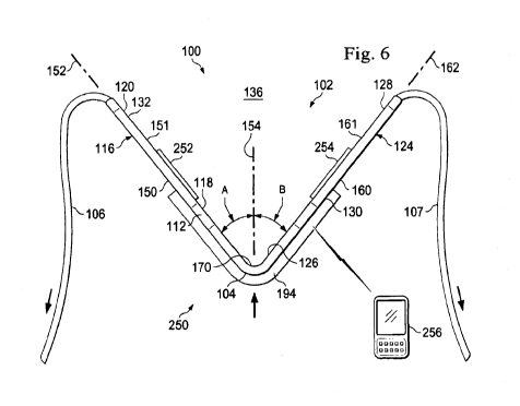
In the exemplary embodiment shown in Figs. 1-6, the pressure detecting system
250
comprises a plurality of strain gauges 252, 254 disposed on the perianal
support member 102
and a user interface 256 (Fig. 6) in communication with the strain gauges 252,
254. In some
embodiments, the strain gauges form a part of the perianal support member 102,
while in
other embodiments, they are adhered to the perianal support member 102. In the
examples
shown, a first strain gauge 252 is attached to the first compression element
116 and a second
strain gauge 254 is attached to the second compression element 124. The strain
gauges 252,
254 are arranged to detect strain in the compression elements 116, 124 in a
manner indicative
of loading applied to the external pressure surface at the anterior end 112 of
the perianal
support member and of loading at the posterior end of the perianal support
member 104 as
applied by the securing members 106, 107. The strain gauges 252, 254 may be
any type of
strain gauge including for example, a mechanical strain gauge, an electrical
resistance strain
gauge, an optical strain gauge, or other type of strain gauge.
Fig. 6 shows the strain gauges communicating with a user interface 256 that is
configured to communicate information relating to the strain on the perianal
support member
102 as detected by the strain gauges 252, 254, which is representative of
pressure being
applied by the perianal support member 102 to the patient. The user interface
256 may
display or otherwise convey to a health care provider or the patient detected
changes in
pressure level, may display or otherwise indicate whether the pressure is
within a suitable
range, or may display or otherwise provide other feedback to the health care
provider or
patient indicative of pressure during the child delivery process. To do this,
the user interface
256 communicates with the strain gauges 252, 254. Depending on the embodiment,
the user
interface 256 may communicate with the strain gauges 252, 254 either by wired
connection
or by a wireless connection. In some embodiments, signals from the strain
gauges are
processed by a processing system, and the user interface may receive
information from the
processing system indicative of information obtained by the strain gauges. In
some
embodiments, the user interface 256 is a table-top device that may be viewed
by the health
care provider or patient. In other embodiments, the user interface is a
handheld structure,
such a fob that may provide information to the health care provider or
patient. Depending on
the embodiment, the user interface may communicate detected information in any
manner
19
CA 02906387 2015-09-14
WO 2014/150041
PCT/US2014/021965
that may be understood by the health care provider or the patient. In one
embodiment, the
user interface 156 displays values from the strain gauges indicative of
strain. In simpler
embodiments, the user interface may display a red light when the absence of
strain indicates
that the perianal support system 100 is not applying a desired pressure to the
perianal support
device and a green light when the detected strain indicates that the perianal
support system
100 is applying pressure within a desired range. Other interfaces are
contemplated. When
the strain gauges 252, 254 are of the type measuring electrical resistance
though a conductor,
the user interface 256 may also serve as a power source for the strain gauges.
Other
embodiments use strain gauges having an on-board power supply. Yet other
arrangements
are contemplated.
Some embodiments have a user interface 256 in the form of a smartphone or
tablet,
such as an iPhone , an Android phone, an iPad , or other similar device that
is wirelessly
connected with sensors 252 and 254. In this embodiment, the user interface 256
may operate
a selectable application that may be downloaded to the user interface. In such
embodiments,
the patient or the healthcare provider may opt to view the information from
the pressure
detecting system on her own personal device. In some embodiments, the user
interface 256
may display a graph with a line tracing the detected pressure as a timeline.
Figs. 4-6 also show a migration barrier 194 that extends at least partially
along the
exterior side wall 150 of the first compression element 116 and at least
partially along the
exterior sidewall 160 of the second compression element 124. In some
embodiments, the
migration barrier may be formed of a soft, flexible silicon material
configured to prevent the
migration of fecal matter that may be expelled during childbirth. In this
embodiment, the
perianal support member may be located over the anus so that the migration
barrier 194 is
disposed between the anus and the vaginal opening. The migration bather 192
may permit
expelled matter to migrate only in the direction away from the vaginal
opening. In the
embodiment, shown, the migration barrier 194 extends at an oblique angle
relative to the axis
152, 162 and may form a curved arc as can be seen by the hidden lines in Fig.
5. Other
embodiments have a different angle and may be for example, purely linear or
otherwise
shaped.
Fig. 5 also shows an indicium 196 that helps a healthcare provider properly
locate the
perianal support member 102 on the patient. In this example, the indicium is a
target shape
CA 02906387 2015-09-14
WO 2014/150041
PCT/US2014/021965
formed on the perianal support member 102. In use, the health care provider
may align the
target with a body reference marker, such as the anus. This may help ensure
the perianal
support member 102 is properly located to support or treat perianal tissue
while maintaining
suitable spacing from the vaginal opening. Although a target shape is shown,
other
embodiments have other shapes or indicia as indicators. Indicia may find
particular utility
when using a transparent perianal support member 102. In this example, the
indicium is
spaced off-center from the axes 152, 162 in order to provide a suitable
position of the
perianal support member 102 on the patient.
Figs. 7-9 show a portion of another exemplary embodiment of a perianal support
system 300 in accordance with an exemplary aspect of the present disclosure.
The support
system 300 may include the perianal support member 102 and the securing
members 106,
107 as described above with reference to the support system 100 in Figs. 1-6.
In this
example, at least a portion of the perianal support member 102 may be formed
of a material
enabling passage of light through the perianal support member 102. In this
embodiment, the
light passing through the perianal support member 102 may be used as an
indication of
whether suitable pressure is being applied on the perianal tissue as explained
below.
In this example, the support system 300 includes a pressure detecting system
302 that
comprises a pressure detecting compliant pad 304 adhered to the perianal
support member
102 across the majority of the pressure surface 104. In some embodiments, the
pressure-
detecting compliant pad 304 has a width the same width as the perianal support
member 102,
and in other embodiments, the pressure-detecting compliant pad 304 has a width
less than the
width of the perianal support member 102. In the embodiment shown the pressure-
detecting
compliant pad 304 extends about the pressure surface 104 and extends at least
partially along
the exterior side wall 150 of the first compression element 116 and at least
partially along the
exterior sidewall 160 of the second compression element 124. The pressure
detecting
compliant pad 304 may be disposed and arranged as an interfacing structure
disposed
between the pressure surface 104 of the perianal support member and a
patient's perianal
tissue when the perianal support system 300 is disposed on a patient. As
illustrated, a first
portion of the complaint pad 304 extends along and is adhered to distal end
portion 118 of the
compression element 116. In a similar manner, a second portion extends along
and is
adhered to distal end portion 126 of the compression element 124. In one
embodiment, the
compliant pad 304 is a sterile gauze pad. In another embodiment, the compliant
pad 304
21
CA 02906387 2015-09-14
WO 2014/150041
PCT/US2014/021965
includes an internal cushioning structure, such as polyurethane, silicon,
rubber, foam, cotton,
etc., with a non-abrasive skin contact surface. The compliant pad 304 may be
adhered to the
perianal support member 102 across the majority of the pressure surface 104.
In one
embodiment, the compliant pad is die cut from 1776 and 1772 stock materials
from 3M. Then
bonding the resulting laminate on to the compression surface as the 1772
material has an
adhesive back. In another embodiment, compliant pad 304 is an absorbent
material adapted to
absorb bodily fluids. It will be appreciated that the compliant pad 304 may
make placement
and maintenance of the support device 300 more comfortable for the patient. In
addition, the
surface of the pad 304 is configured to frictionally engage the patient's
perianal tissue to
inhibit movement between the support device 300, particularly the pressure
surface 104 and
the patient. In still a further aspect, compliant pad 304 includes a treating
compound. The
treating compound is disposed within the pad, applied on the surface, or a
combination of
both. Treating compounds useful for combination with pad 304 include, but
without
limitation to other compounds, antibacterial compounds, antibiotic compounds,
sclerants,
antimicrobial compounds, anti-inflammatory compounds, anti-fungal agents, anti-
itching
agents, humicants, moisture absorbing agents, gas absorbing agents, buffering
agents for pH
control, drying agents and the like and coagulants. In yet a further
embodiment, pad 304 is
not fixed to the perianal support member 102 but is instead positioned on the
patient in
advance of positioning the perianal support member 102 or is loosely held to
the perianal
support member 102 as it is applied to the body. In this embodiment, perianal
support
member 102 maintains the position of the pad 304 relative to the patient's
body and in
particular the anal orifice.
In one embodiment, the compliant pad 304 is a flexible fabric pressure sensor
formed
of an outer layer arranged to interface with and apply pressure to the
perianal tissue of the
patient, a stretch conductive fabric, an Ex-static fabric, a non-conductive
adhesive, an
energy source, a light source, and connection cables. A microcontroller may
translate sensor
values into the output values into a signal indicative of pressure.
In an alternative embodiment, the pressure detecting compliant pad 304 may be
designed to change colors when pressure on the pad exceeds a threshold
pressure. The
threshold pressure may be preset and may be established to correspond with a
therapeutic
pressure that is considered suitable to support the perianal tissue of the
patient during the
child delivery process. In one exemplary embodiment, the pad 304 is a Mylar
based film that
22
CA 02906387 2015-09-14
WO 2014/150041
PCT/US2014/021965
contains a layer of tiny microcapsules. The application of force upon the pad
causes the
microcapsules to rupture, producing an instantaneous and permanent high
resolution
"topographical" image of pressure across the contact area. A film having such
a construction
is marketed under the trade name FujiFilm Prescale . Some compliant pad
embodiments
include a liquid gel covering a colored backing. Under pressure, the gel
displaces revealing
the colored backing, and indicating to the health care provider that a
pressure threshold has
been met. Other types of color indicators are also contemplated.
Some embodiments of the pressure detecting compliant pad are configured to
dynamically display the color from a low intensity color to a higher intensity
color indicative
of the amount of pressure. Such pads showing a graduated scale may also
indicate when the
pressure exceeds therapeutic pressure. When such instances occur, the
healthcare provider
may adjust the perianal support member 102 to reduce the pressure on the
perianal tissue. In
some embodiments, the pressure detecting compliant pad 304 operates as a
pressure switch,
where the pad 304 is a first color when the switch is off, and where the pad
changes color
when the switch is on.
Since the perianal support member 102 allows passage of at least some visible
light, a
health care provider may be able to visually determine when a therapeutic
pressure is applied
on the pressure-detecting compliant pad 304 based on the color emitted from
the pressure
detecting compliant pad 304. In some aspects, the health care provider, even
when
positioned to receive a baby during delivery, can visually observe at least
some light emitted
from the pressure-detecting compliant pad 304 be observing through the
internal contact
surface 170 in the access cavity 136 of the perianal support member 102. In
some
embodiments, the perianal support member 102 is formed of a clear plastic
material that
enables a health care provider to directly see the pressure detecting
compliant pad 304. Some
clear plastic materials may include acrylics or other types of polymer
materials. Other
embodiments are only partially transparent and may permit passage of light
through the
perianal support member 102 so that a health care provider can visually
observe the color of
the pressure-detecting compliant pad. A partially transparent perianal support
member may
visually cover the patient tissue under pressure but may still permit the
changes in color to be
recognized by the health care provider.
23
CA 02906387 2015-09-14
WO 2014/150041
PCT/US2014/021965
In some embodiments, the pressure detecting compliant pad 304 may include a
power
source that provides power to electronics for emitting a light or for causing
the pressure
detecting compliant pad 304 to emit light of a particular color. Other
embodiments undergo a
chemical reaction or other transformation when the threshold pressure level is
exceeded. The
reaction or transformation causes the color change in the pressure detecting
compliant pad
304.
Figs. 10-12 show a portion of another exemplary embodiment of a perianal
support
system 350 in accordance with an exemplary aspect of the present disclosure.
This
exemplary embodiment includes a pressure detecting compliant pad as discussed
above,
however the pad operates as a switch associated with an LED indicator. When
the desired or
the therapeutic pressure is reached on the pressure detecting compliant pad,
the bulb may be
turned on as an indicator to indicate to the health care provider that the
threshold therapeutic
pressure has been met. The support system 350 disclosed herein includes a
perianal support
member 352 and a pressure detecting system 354. The pressure detecting system
includes a
pressure detecting compliant pad 360 and an LED bulb 362. These are discussed
further
below. The perianal support member 352 has many of the same features and shape
as the
perianal support member 102 discussed above. Therefore a description of the
entire perianal
support member 352 will not be repeated here recognizing that the description
above applies
to the perianal support member 352. However, in this embodiment, the perianal
support
member 352 includes a thick pressure zone 356 disposed between the external
pressure
surface 104 and the internal contact surface 170. The thick pressure zone 356
is configured
to house a portion of the pressure detecting system 354. In this embodiment,
the thick
pressure zone 356 has a thickness greater than the thickness of the LED bulb
362, and fully
encompasses the LED bulb 362. Because of its shape, the perianal support
member 352
includes an external pressure surface 104 similar to that discussed above, and
the internal
contact surface 170 has a curved surface that is not concentric with the
external pressure
surface 104. In some embodiments, the internal contact surface 170 is a planar
surface
extending between the first and second compression elements. In use, a health
care provider
can manually provide pressure on the internal contact surface 170 to hold the
perianal support
member 352 in place on the patient until the first and second securing members
are properly
positioned. The thick pressure zone 356 fully encompasses the LED bulb 362 and
protects
24
CA 02906387 2015-09-14
WO 2014/150041
PCT/US2014/021965
the LED bulb 362 from damage that might otherwise occur when the health care
provider
applies pressure on the internal contact surface 170.
The pressure detecting compliant pad 360 in this embodiment is responsive to
changes in pressure and may be a pressure switch responsive at a repeatable
and preset
pressure. In some embodiments, a pressure detecting compliant pad 360 may be
formed of
an outer layer arranged to interface with and apply pressure to the perianal
tissue of the
patient, a stretch conductive fabric, an Ex-static fabric, a non-conductive
adhesive, an
energy source, a light source, and connection cables. A microcontroller may
translate
detected pressure into output signals indicative of the detected pressure.
The LED bulb 362 may form a part of a circuit with the pressure detecting
compliant
pad 360 and may be in electrical communication with the pressure detecting
compliant pad
360. A power source (not shown) may also be disposed adjacent the LED bulb 362
in the
thick pressure zone 356 of the perianal support member 352. Although LED's are
provided
for the purpose of illustration, the type of visual indicator is not limited
to LED's and other
light sources or visual indicators can be utilized with the present
disclosure.
In some embodiments, the LED bulb 362 is a multi-colored LED bulb with each
color
indicative of a separate pressure threshold. In one exemplary embodiment, no
light may
indicate pressure below a minimum threshold and the LED bulb 362 may display
green after
exceeding a first pressure threshold. The green zone of pressure may provide
static support
pressure indication capability which may correspond to a pressure range that
provides
therapeutic support in a relatively static condition. During contractions and
after exceeding a
second pressure threshold, the LED may change to yellow indicating an increase
in pressure.
This yellow zone may provide dynamic support pressure indication capability,
which may
suggest that the patient is effectively pushing the baby toward the vaginal
opening during the
contraction. The yellow light is intended to provide dynamic feedback during
the dynamic
stages of a contraction. In still an alternative feature, if a third pressure
threshold is
exceeded, the LED may change to red to indicate an unsafe pressure range. This
red zone
may provide extreme support pressure indication capability indicating that
pressure on the
perianal tissue should be reduced. Therefore, this condition alerts the user
to either cease the
pushing contractions or reposition or remove the perianal support device. The
first, second,
and third pressure thresholds may be selected to correspond to desired
therapeutic pressures.
CA 02906387 2015-09-14
WO 2014/150041
PCT/US2014/021965
For example, the LED bulb 362 may shine with a green light when the first
pressure
threshold is exceeded indicating that a partially effective pressure is being
applied to the
perianal tissue, and may shine with a yellow light when the second pressure
threshold is
exceeded indicating that more effective pressure is being applied to the
perianal tissue.
In another embodiment, the LED bulb 362 is not embedded in a thick pressure
zone,
but is disposed on the perianal support member 352 in a manner that the LED
bulb may be
monitored by the health care provider. In this embodiment, pressure on the
compliant pad
360 may switch on the LED bulb 362 which may be disposed anywhere along the
perianal
support member 352. In such embodiments, the transparency of the perianal
support member
352 does not impact the effectiveness of the pressure detecting system 354.
Figs. 13 and 14 show a portion of another exemplary embodiment of a perianal
support system 400 in accordance with an exemplary aspect of the present
disclosure. This
exemplary embodiment includes a perianal support member 402 and a pressure
detecting
system 404 that includes a transmitter 106 and an off-board receiver 408. In
this
embodiment, the perianal support member 402 is shaped in the same manner
discussed above
with reference to Figs. 10-12 and includes a thick pressure zone 356 at the
apex between the
external pressure surface 104 and the internal contact surface 170. In this
embodiment
however, the pressure detecting system 404 includes a transmitter 406, a
receiver 408, and a
pressure detecting compliant pad 410. The transmitter 406 is disposed on the
perianal
support member 402 in addition to or in place of the LED bulb 362 shown in
Figs. 11 and 12.
The transmitter 406 is in communication with the pressure detecting compliant
pad 410 and
may be configured to receive signals indicative of pressure detected by the
pressure detecting
compliant pad 410. In some embodiments, the signals may have been processed by
a
microcontroller carried on or otherwise in communication with the pressure
detecting
compliant pad 410. In some embodiments, the signals may be directly
transmitted signals
representative of pressures detected by the pressure detecting compliant pad
410. In other
embodiments where the pressure detecting compliant pad 410 is a pressure
switch, the signals
may be an on/off signal indicative of an open or closed circuit.
Depending on the embodiment, the transmitter 406 may communicate using any uni-
directional or bi-directional radio communication format. Different
embodiments include, for
example, a Wi-Fi bi-direction radio communication capability and a Bluetooth
bi-direction
26
CA 02906387 2015-09-14
WO 2014/150041
PCT/US2014/021965
radio communication capability that allow wireless communication following the
Wi-Fi
Alliance standard and Bluetooth Special Interest Group standard. Of course,
other wireless
local area network (WLAN) standards and wireless personal area networks (WPAN)
standards can be used.
The transmitter 406 transmits signals from the perianal support member 402 to
the
off-board receiver 408. The receiver 408 may comprise an antenna, and receiver
circuitry for
processing the signals received from the transmitter 406. Depending on the
embodiment, the
receiver 108 may include a microprocessor configured to interpret the signals
and output
information via a user interface to a health care provider or the patient. In
one embodiment,
the processor is configured to output actual pressure values acting on the
pressure detecting
compliant pad 410. In other embodiments, the microprocessor is configured to
output
information indicating to the health care provider whether more pressure or
less pressure is
recommended in order to reduce the incidence of perianal tissue damage. In one
embodiment, the receiver 408 is configured with a simple user interface that
indicates
whether the applied pressure is above or below a therapeutic pressure
threshold. In this
embodiment, the user interface may be a single bulb that turns on when the
signal from the
transmitter indicates that the therapeutic pressure threshold has been
reached.
Although disclosed as being used with the pressure detecting compliant pad
410, the
transmitter 406 and receiver 408 may be used with any pressure sensing system
disclosed
herein, including the strain gauges, the visual indicator pad, the LED
indicator, as well as the
others. The off-board receiver 408 may store and record information obtained.
In one
example, the information is displayed over time.
When the receiver 408 is in the form of a smartphone or tablet, such as an
iPhone ,
an android phone, an iPad , or other similar device as discussed above, the
receiver may
process and display the information received from the transmitter on a screen.
In some
embodiments, the receiver 408 communicates with the transmitter via blue-
tooth, while in
other embodiments, the communications occur over a Wi-Fi network.
As discussed above with reference to Figs. 1-3, the perianal support system
100
includes the first and second securing members 106, 107. Figs. 15-28 show
different
securing members that may secure the perianal support member against the
perianal tissue of
the patient. Depending on the embodiment, the securing members may attach to
the patient,
27
CA 02906387 2015-09-14
WO 2014/150041
PCT/US2014/021965
such as the patient's flanks, or may extend between the perianal support
member and anchor
pads. Other securing members extend between the perianal support member and
the patient
or inanimate objects, such as a part of the delivery bed. The securing members
disclosed
herein may be configured and arranged to provide an indication, such as a
visual indication
for example, of the load being applied on the perianal tissue by the perianal
support member.
In some embodiments, the securing members are arranged to indicate when a
suitable
therapeutic load is applied to the perianal tissue based on the tension
applied to the securing
members.
Figs. 15 and 16 shows an exemplary pressure detecting system 500 comprising a
securing member 502 that may be employed to secure the perianal support member
102 in
place of the securing member 106 or 107 discussed above. Here, the pressure
detecting
system 500 also includes a pressure detecting portion 504. Some embodiments
employ two
securing members, and each securing member may include the same features. In
other
embodiments, only one securing member forms the pressure detecting system 500,
and the
other securing member does not form the pressure detecting system 500 as it
may not provide
feedback to the health care provider or patient.
The securing member 502 may be formed of a substantially elastically extending
or
substantially non-extending strap. In this embodiment, it includes a
connection portion 506
to which a portion of a hook and loop fastener may be adhered. The hook and
loop fastener
may enable the securing member 502 to be adhered in place to a corresponding
hook and
loop fastener, such as an anchor pad. A health care provider can stretch the
securing member
502 to the increase or decrease the load applied on perianal tissue by the
perianal support
member.
The pressure detecting portion 504 in this embodiment is a tension detecting
pad. The
tension detecting pad is arranged to detect strain during the loading process
and provide
information to a user indicative of the amount of loading on the securing
member 502. In one
embodiment, it does this by changing colors, thereby providing a visual
indicator to the
health care provider or patient of the amount of loading on the securing
member 502. The
amount of strain on the securing member 502 may be directly correlated with
the amount of
pressure on the perianal tissue. In one embodiment, the pressure detecting
portion 504
changes color depending on the amount of strain or stretch. The amount of
stretch is directly
28
CA 02906387 2015-09-14
WO 2014/150041
PCT/US2014/021965
correlated with the loading on the perianal support member, and therefore, the
color
displayed by the pressure detecting portion 504 is directly correlated with
loading on the
perianal support member. In one example the pressure detecting portion 504 is
a neutral
color when in an unloaded or a neutral condition, and changes to a green color
when the
tension in the securing member 502 is sufficient to provide a desired load on
the perianal
tissue by the perianal support member. In some embodiments, the color changing
abruptly
occurs when a strain that applies a therapeutic pressure is reached, and in
other embodiments,
the color change is graduated so that a health care provider or the patient
can determine about
what loading is being applied at any one time. Accordingly, the securing
member 502 may
be applied to a patient in an initial static support position. Color changes
during contractions
indicate higher pressures. As such, the device may provide positive user
feedback on
dynamic pressure changes indicative of the success or lack thereof of pushing
associated with
contractions. It's worth noting that the perianal support system may be
retained in position
both during the static support phase and the dynamic support phase of the
birthing process.
In some embodiments, the securing member 502 is formed of an elastically
extending
strap with elastomeric properties enabling the securing member 502 to stretch
from a neutral
condition when no load is applied to a stretched condition, when the securing
member 502 is
under a tension load. In such an embodiment, the strain or the stretch under
load may be
much greater than in other embodiments where the securing member 502 formed of
a
substantially non-elastic material. In such embodiments, the securing member
502 has elastic
spring properties, such that the greater the distance of the stretch, the
greater the load
required. Other embodiments have a substantially non-elastic securing member
502.
Accordingly, the amount of strain is much less under load. The color changing
indicator pad
may be arranged to correspond with a particular securing member property type
in order to
provide a repeatable indicator to the health care provider or patient. In some
embodiments,
the securing member 502 is formed of a thin-napped Lycra material.
Fig. 15 shows the securing member 502 and the pressure detecting portion 504.
In
Fig. 15, the securing member is under a first load or is under no load.
Therefore, the pressure
detecting portion is a first color. In Fig. 16, the pressure detecting
securing member 502 is
under a second, greater load, and has introduced an increased level of strain
into the securing
member 504. As can be seen, the color is pad is also lengthened and as a
result, displays a
different color. While shown as making up only a portion of the securing
member 502, in
29
CA 02906387 2015-09-14
WO 2014/150041
PCT/US2014/021965
some embodiments, the pressure detecting portion 504 has the same width and/or
length as
the securing member 502 and in some embodiments, the pressure detecting
portion 504
makes up the entire securing member 502.
Figs. 17 and 18 show another embodiment of an exemplary pressure detecting
system
520 comprising a securing member 522 that may be employed to secure the
perianal support
member 102 in place of the securing member 106 or 107 discussed above. Here,
the pressure
detecting system 520 also includes a pressure detecting portion 524 that may
provide
information to the health care provider or patient that a sufficient tension
is reached to apply a
desired load through the perianal support member 102 onto the perianal tissue.
This
embodiment is similar in many respects to the pressure detecting system 500
discussed
above. However, this embodiment includes an electrical light indicator 526 in
place of the
color changing indicator tension detecting pad discussed above. In this
embodiment, the
strain or change in length of the strap can be monitored and used to provide
feedback to the
light indicator 526. The light indicator 526 is, in the embodiment shown, an
LED bulb that is
configured to emit light when powered. Leads on the LED connect to a power
source and to
a strain detector that may operate as a switch when the strain exceeds a
threshold strain. The
threshold strain may be selected to correspond to a desired pressure on the
perianal tissue
when the securing member 522 is angled to provide the loading through the
perianal support
member. In one embodiment, the angle is one shown in Fig. 1, where the
securing member
extends to the lateral flanks.
Fig. 17 shows the securing member 522 and the pressure detecting portion 524.
In
Fig. 17, the securing member 522 is under a first load or is under no load.
Therefore, the
pressure detecting portion 524 is off, or is not lit. In Fig. 15, the pressure
detecting securing
member 522 is under a second, greater load, and has introduced a sufficient
level of strain
into the securing member 522. As can be seen, the pressure detecting portion
524 is therefore
on, powered, or lit, indicating that the securing member 522 is under a
tension load sufficient
to apply suitable tension on the perianal tissue.
Figs. 19 and 20 show another embodiment of an exemplary pressure detecting
system
540 comprising a securing member 542 that may be employed to secure the
perianal support
member 102 in place of the securing member 106 or 107 discussed above. Here,
the pressure
detecting system 540 also includes a pressure detecting portion 544 that may
provide
CA 02906387 2015-09-14
WO 2014/150041
PCT/US2014/021965
information to the health care provider or patient that a sufficient tension
is reached to apply a
desired load through the perianal support member 102 onto the perianal tissue.
In this
embodiment, the securing member 542 is an elastically extending member that
may extend
from a neutral or un-stretched condition to a stretched condition. In some
embodiments, the
securing member 542 has elastic properties where the tension force increases
non-linearly as
the material is stretched.
The pressure detecting portion 544 in this embodiment comprises a plurality if
inelastic fibers or indicators whose profiles provide an indication of tension
loading on the
pressure detecting system 540. The pressure detecting portion 544 can be seen
in both Figs.
19 and 20. In Fig. 19, the inelastic fibers are curved or are not straight.
This may indicate
that the tension loading on the securing member 542 is less than a threshold
pressure, and
therefore, the securing member 542 is not providing a desired load on the
perianal tissue
through the perianal support member. Fig. 20 shows the securing member 542
stretched
further than in Fig. 19. As a result, the inelastic fibers have straightened
out. In this
embodiment, the securing member and the pressure detecting portion 544 is
designed so that
the desired pressure on the perianal tissue corresponds with the straightening
of the inelastic
fibers. Accordingly, when the inelastic fibers are substantially straight, the
pressure on the
perianal tissue has reached or exceeded the desired loading on the perianal
tissue. The fiber
profile in Fig. 20 corresponds to a desired pressure on the perianal tissue.
Figs. 21-24 show yet another embodiment of an exemplary pressure detecting
system
560 comprising a securing member 562 that may be employed to secure the
perianal support
member 102 in place of the securing member 106 or 107 discussed above. Figs.
21 and 22
show the pressure detecting system 560 in an un-stretched state and Figs. 23
and 24 show the
pressure detecting system 560 in a stretched state. Figs. 21 and 23 show a top
view of the
pressure detecting system 560 and Figs. 22 and 24 show side views. Here, the
pressure
detecting system 560 also includes a pressure detecting portion 564 that may
provide
information to the health care provider or patient that a sufficient tension
is reached to apply a
desired load through the perianal support member 102 onto the perianal tissue.
In this
embodiment, the securing member 562 is an elastically extending member that
may extend
from a neutral or un-stretched condition to a stretched condition as discussed
above.
31
CA 02906387 2015-09-14
WO 2014/150041
PCT/US2014/021965
The pressure detecting portion 564 is in this embodiment comprises an
inelastic strap
or indicator whose profile provides an indication of tension loading on the
pressure detecting
system 560. The pressure detecting portion 564 can be seen best in Figs. 21
and 23. In Figs.
19 and 20, the inelastic strap is not stretched or is not taut. This may
indicate that the tension
loading on the securing member 562 is less than a threshold pressure, and
therefore, the
securing member 562 is not providing a desired load on the perianal tissue
through the
perianal support member. Figs. 21 and 22 show the securing member 542
stretched further
than in Figs. 19 and 20. As a result, the inelastic strap has straightened
out. In this
embodiment, the securing member 562 and the pressure detecting portion 564 are
designed so
that the desired pressure on the perianal tissue corresponds with the
straightening of the
inelastic strap. Accordingly, when the inelastic strap is substantially
straight, the pressure on
the perianal tissue has reached or exceeded the desired loading on the
perianal tissue.
Figs. 25 and 26 show another embodiment of an exemplary pressure detecting
system
580 comprising a securing member 582 that may be employed to secure the
perianal support
member 102 in place of the securing member 106 or 107 discussed above. Fig. 25
shows the
pressure detecting system 580 in an un-stretched state and Fig. 26 shows the
pressure
detecting system 580 in a stretched state. Here, the pressure detecting system
580 also
includes a pressure detecting portion 584 that may provide information to the
health care
provider or patient that a sufficient tension is reached to apply a desired
load through the
perianal support member 102 onto the perianal tissue. In this embodiment, the
securing
member 582 is an elastically extending member that may extend from a neutral
or un-
stretched condition to a stretched condition as discussed above.
The pressure detecting portion 584 in this embodiment comprises a reference
shape or
indicator formed in the elastic strap whose profile provides an indication of
tension loading
on the pressure detecting system 580. The pressure detecting portion 584 is
shown in Fig. 25
having a series of non-square rectangular shapes in an un-stretched state.
This may indicate
that the tension loading on the securing member 562 is less than a threshold
pressure, and
therefore, the securing member 562 is not providing a desired load on the
perianal tissue
through the perianal support member. As the securing member 582 is stretched,
the shape of
series of non-square rectangular shaped changes to a square shape. This may
indicate that a
desired tension is in the securing member 582 sufficient to apply a desired
load on the
32
CA 02906387 2015-09-14
WO 2014/150041
PCT/US2014/021965
perianal tissue through the perianal support member 102 when the securing
member is
applied in a particular location, such as along the lateral flanks of the
patient.
The securing member 582 and the pressure detecting portion 584 are designed so
that
the desired pressure on the perianal tissue is achieved when the shape of the
pressure
detecting portion 584 becomes square. Accordingly, when the shape of the
pressure
detecting portion 584 is substantially square, the pressure on the perianal
tissue has reached
or exceeded the desired loading on the perianal tissue. While the shape is
shown as square in
the embodiment shown, other shapes are contemplated including, for example,
any geometric
figure, such as circles, stars, and so on. The shapes may be imprinted at
intervals or woven or
otherwise incorporated into the fabric of the securing member 582.
Figs. 27 and 28 show another embodiment of an exemplary pressure detecting
system
600 comprising a securing member 602 that may be employed to secure the
perianal support
member 102 in place of the securing member 106 or 107 discussed above. Fig. 27
shows the
pressure detecting system 600 in an un-stretched state and Fig. 58 shows the
pressure
detecting system 600 in a stretched state. Here, the pressure detecting system
600 also
includes a pressure detecting portion 604 that may provide information to the
health care
provider or patient that a sufficient tension is reached to apply a desired
load through the
perianal support member 102 onto the perianal tissue. In this embodiment, the
securing
member 602 is an elastically extending member that may extend from a neutral
or un-
stretched condition to a stretched condition as discussed above, and the
pressure detecting
protion 602 is one or more strain gauges that measure the strain or extension
of the securing
member 602 in the manner discussed above. In this embodiment, each strain
gauge is
associated with a wireless transmitter that transmits the detected information
to an off-board
interface device 608 that may communicate information to the health care
provide or the
patient. The off-board interface device 608 and the transmitter may work in a
manner similar
to those discussed above and may display either information related to the
real-time pressure
or may display threshold information indicating whether the pressure is above
or below the
threshold.
The pressure detecting portions disclosed herein may enable a health care
provider of
the patient to apply the perianal support device with at least a proper amount
of pressure to
provide therapeutic support to the patient during childbirth. Accordingly, the
perianal device
33
CA 02906387 2015-09-14
WO 2014/150041
PCT/US2014/021965
may reduce the incidence of a number of complications, including for example
and without
limitation, pelvic floor incompetence or dysfunction, organ prolapse,
incontinence secondary
to pressure and stretching exerted on bladder and bladder neck, over
stretching, perineum
tears and lacerations, forceps use, and hemorrhoids.
In some embodiments, the perianal support systems describe herein are
configured to
count uterine contractions by monitoring the pressure changes invoked on the
perianal
support member 102 by the perianal tissue. That is, during contractions, the
perianal support
systems described herein may be configured to detect a change in pressure that
occurs due to
muscle displacement of the perianal tissue. During labor, the contractions of
the uterus,
along with movement of the baby's head as a result of the uterine muscles,
physically
displace the perianal tissue. When the perianal tissue is supported by the
perianal support
systems described herein, the result is less perianal tissue displacement and
an increase in net
pressure against the external pressure surface 104 of the perianal support
member 102. These
increases in pressure against the pressure surface 104 can be detected using
the pressure
detecting systems described above. Accordingly, in addition to measuring the
pressure
statically upon application of the perianal support device, the system may be
used to monitor
dynamic pressure by detecting changes in pressure at the perianal tissue
resulting from
uterine contractions.
Any of the embodiments described herein may also be used to mechanically or
electrically count uterine contractions by monitoring the changes in pressure
that occur
during each contraction. An exemplary mechanical counter includes for example,
a spring
loaded plunger that may displace with displacement of perianal tissue. The
plunger may
drive a cog or gear to rotate a counting mechanism in a manner similar to hand-
held
mechanical counters that count the times a plunger is pressed. The counter may
display a
number disposed for viewing on a numbered wheel indicative of the number of
times the
plunger presses or the tissue displaces. Some embodiments employ the user
interfaces
described above to count each time that the pressure changes by a pre-
programmed amount.
For example, the pressure detection system may store count each time the
pressure increases
by a pre-set amount or each time the pressure exceeds a threshold level. In
addition to
counting the contractions, the system may also determine the time between
contractions.
Depending on the embodiment, this information may be stored and displayed to a
user using
any of the interfaces disclosed herein. In some embodiments, the pressure may
be shown in
34
CA 02906387 2015-09-14
WO 2014/150041
PCT/US2014/021965
real-time as a graph on the user interface devices. Pressure peaks may
indicate the start of a
contraction, and the time period between peaks may be indicative of the time
between
contractions.
Any of the embodiments described herein may also make up a push meter
configured
to provide an indication of the strength of a push during the birthing
process. For example,
by monitoring the changes in pressure on the perianal tissue by the support
member 102 that
occur during a push, the pressure detection systems may be able to provide a
pressure
indication of the strength of a push. In some embodiments, the strength of the
push may be
displayed on a user interface in a graph form on a user interface. In other
embodiments, the
strength of the push may be indicated by the color change, the light bulb
activation or other
indicator described herein or that might otherwise indicate the strength of a
push.
Accordingly, during the birthing process, the patient and/or the healthcare
provider may
observe the systems to determine the strength of a push.
Figs. 29 and 30 show yet another embodiment of a perianal support system,
referenced by the numeral 650. This embodiment is similar in many ways to the
support
system 100 shown and discussed above, and may include any of the features or
pressure
detecting systems disclosed herein. Like the support system 100, the support
system 650
includes the perianal support member 102 having the external pressure surface
104 and the
securing members 106, 107 for attachment to a patient. In addition, the system
650 includes
device adjustment elements 652, 654. The device adjustement elements 652, 654
extend
from the perianal support member 102 or the securing members and are
configured and
arranged to permit the patient to adjust the support system 650. The
adjustment may include
modifying the pressure applied by the support system 650 on the perianal
tissue or may
include adjusting the physical location of the perianal support member 102 on
the patient.
Accordingly, during contractions or during pushing, the patient can apply
additional pressure
on the perianal tissue if desired. Therefore, the patient has some level of
control of the
pressure on the perianal tissue.
In this embodiment, the device adjustment elements 652, 654 are straps that
extend
from a location adjacent the perianal support member 102 in the same direction
as the
securing members 106, 107. These device adjustment elements 652, 654 may be
flexible and
may be substantially non-elastic so that the patient can easily pull the
straps toward her head
CA 02906387 2015-09-14
WO 2014/150041
PCT/US2014/021965
to increase the relative pressure on the perianal tissue or may release the
tension in the straps
to reduce the relative pressure on the perianal tissue. In the exemplary
embodiment shown,
the device adjustment elements 652, 654 respectively include a distal end 656,
658 and a
proximal end 672, 674. The distal end 656 is disposed adjacent to or is
connected to the
proximal end portion of the compression element 116, and the distal end 658 is
disposed
adjacent to or is connected to the proximal end portion of the compression
element 124.
The proximal ends 672, 674 each include a handle portion 678, 680 disposed
therein
that enable the patient to hold the device adjustment elements 652, 654. In
the example
shown, the handle portions 678, 680 are through holes in the device adjustment
elements 652,
654 that enable a portion of the patient's hand or fingers to extend
therethrough. In other
embodiments, the handle portion is formed of a rolled distal end to provide a
gripping
portion. In yet other embodiments, the handle portion is coated with
polyurethane or other
friction enhancing material to allow the patient to comfortably grip the
device adjustment
elements 652, 654 and provide pressure.
The device adjustment elements 652, 654 extend from or adjacent the perianal
support
member 102 and are shaped and arranged to extend around the patients' flanks.
The securing
members 106, 107 may secure the support system 650 in place when the patient
is not
providing additional pressure loading. When additional pressure loading is
desired, the
patient may pull the device adjustment elements 652, 654 so that the device
adjustment
elements 652, 654 tighten around the patient's flanks and apply additional
loading onto the
perianal tissue. In the same manner discussed above, since the compression
elements 116,
124 extend out beyond the crown of the buttocks, additional pulling on the
straps by the
patient results in an increase in pressure through the perianal support member
102 onto the
perianal tissue of the patient. In some embodiments, the patient may monitor
any of the
pressure detecting systems described herein, and may adjust the support system
using the
device adjustment elements 652, 654 to maintain the applied pressure in a
desired pressure
range.
Fig. 31 shows an alternative embodiment of a perianal support system 700 using
the
perianal support member 102, but employing device adjustment elements that are
integrated
with the securing members. The support system 700 includes the perianal
support member
36
CA 02906387 2015-09-14
WO 2014/150041
PCT/US2014/021965
102 as described above for supporting perianal tissue, device adjustment
elements 702, 704,
and anchor pads 706, 708.
The device adjustment element 702 has a distal end 714 and a proximal end 716.
In
the embodiment shown, the distal end 714 attaches to and extends from the
proximal end
portion 120 of the first compression element 116. Similar to the device
adjustment element
652 described above, the device adjustment element 702 is an elongated strap
and includes a
handle portion 718 formed therein. The handle portion 718 may be formed in any
manner, as
discussed above. In this embodiment, the device adjustment element 702
includes a surface
(facing away in Fig. 31) forming a first half of a fastening system. Here, the
surface includes
a fastening portion such as a hook and loop system or a releasable adhesive
system.
The device adjustment element 704 is similar to the device adjustment element
702
and includes a distal end 724 and a proximal end 726. In the embodiment shown,
the distal
end 724 attaches to and extends from the proximal end portion 128 of the
second
compression element 124. Similar to the device adjustment element 702, the
device
adjustment element 704 is an elongated strap and includes a handle portion 728
formed
therein. The handle portion 728 may be formed in any manner, as discussed
above. In this
embodiment, the device adjustment element 704 includes a surface (facing away
in Fig. 31)
forming a first half of a fastening system. Here, the surface includes a
fastening portion such
as a hook and loop system or a releasable adhesive system.
In this exemplary embodiment, the anchor pads 706, 708 are identical and only
the
anchor pad 706 will be described, recognizing that the description equally
applies to the
anchor pad 708. The anchor pad 706 includes an outer facing side 730 and an
inner facing
side (not shown in Fig. 31). The outer facing side 730 includes a fastening
portion 732
configured to fasten to the fastening surface of the adjustment element 702.
In this
embodiment, the fastening portion is one of a hook or loop of a hook and loop
fastener. The
inner facing side is opposite the outer facing side 730 and is configured to
interface with the
patient. In one embodiment the inner facing side comprises an adhesive
configured to adhere
the anchor pad 706 to the patient's' skin, as discussed above. The anchor pad
706 also
includes a guide 736 disposed thereon. The guide 736 is arranged to guide the
device
adjustment element 702 so that the distal portion 714 of the device adjustment
element 702 is
maintained in its lateral position while allowing the distal portion 714 to
move in a
37
CA 02906387 2015-09-14
WO 2014/150041
PCT/US2014/021965
substantially axial direction through the guide 736. In this embodiment, the
guide 736 is a
loop through which the device adjustment element 702 extends. However other
embodiments include other types of guides.
The device adjustment elements in Fig. 31 allow a patient to quickly and
easily adjust
the position of the perianal support member 102 on the perianal tissue and to
increase the
pressure on the perianal tissue. In this embodiment, the patient may adjust
the position or the
pressure applied by the perianal support member 102 by manipulating the device
adjustment
elements 702, 704 relative to the anchor pads 706, 708. First, a health care
provider may
assist the patient by applying the perianal support member 102 in a proper
position adjacent
the perianal tissue on then patient, and with the device adjustment elements
702, 704
respectively fastened to the anchor pads 706, 708. The perianal support member
102 may be
placed in a first therapeutic static pressure engaging position having a first
pressure. The
patient may then adjust the perianal support member 102 to apply a second,
even higher
pressure to resist contractions by laterally displacing the proximal ends of
the device
adjustment elements 702, 704 so that the inner fastening surfaces detach from
the fastening
portion 732 on the outer facing surfaces 730 of the anchor pads. With the
device adjustment
elements 702, 704 detached from the fastening portion 732, 734, the device
adjustment
elements may be axially displaced through the guides 736 to displace the
perianal support
member 102 in the lateral directions or to increase or decrease the pressure
applied by the
perianal support member 102 on the perianal tissue. When the perianal support
member 102
is positioned as desired at the desired pressure, the patient may manipulate
the device
adjustment elements 702, 704 so that they reattach to the fastening portion
732 thereby
securing the device adjustment elements and the perianal support member 102 in
place on the
patient. Again, the support system may be manipulated or adjusted as discussed
herein to
provide a desired pressure on the perianal tissue based on feedback provided
by the pressure
detecting systems.
Fig. 32 shows a portion of yet another exemplary embodiment of a perianal
support
system 750 in accordance with an exemplary aspect of the present disclosure.
The support
system 750 may include the perianal support member 102 and the securing
members 106,
107 as described herein. However, Fig. 32 shows an exploded view of a pressure
detecting
system 752 that comprises a pressure sensor 754 and a compliant pad 756. Here,
the pressure
sensor 754 is disposed between the pressure surface 104 and the compliant pad
756.
38
CA 02906387 2015-09-14
WO 2014/150041
PCT/US2014/021965
Fig. 33 shows a portion of yet another exemplary embodiment of a perianal
support
system 780 in accordance with an exemplary aspect of the present disclosure.
The support
system 780 may include the perianal support member 102 and the securing
members 106,
107 as described herein. The support system 780 includes a pressure sensor 782
and a
compliant pad 784. In this embodiment however, the pressure sensor 782 is
disposed within
the compliant pad 784. Here, the compliant pad 784 comprises a pouch or pocket
786 with
an opening formed therein for receiving the pressure sensor 782. The pressure
sensor 782
may be introduced to the compliant pad 784 in the birthing room or at the
manufacturing
facility. The pocket 786 may maintain the pressure sensor at the desired
location to detect
pressure applied against the perianal tissue.
Fig. 34 shows yet another exemplary embodiment of a perianal support system
800 in
accordance with an exemplary aspect of the present disclosure. The support
system 800 may
include the perianal support member 102 and the securing members 106, 107 as
described
above with reference to the support system 100 in Figs. 1-6. In addition, the
support system
800 includes a pliable receptacle or bag 802 disposed along the inner surface
132 in the area
of the access cavity 136. In some examples, the pliable receptacle or bag 802
is a cooling
applicator configured to receive and maintain a therapeutic cooling material,
such as an ice, a
frozen gel, or other ice-pack like material adjacent the perianal tissue. The
pliable receptacle
or bag 802 is configured to be opened, to receive the cooling material, and to
be closed to
maintain the therapeutic cooling material in place adjacent the perianal
tissue. In some
embodiments, the perianal support member 102 is formed of a thermally
conductive material
that may transfer at least a part of the temperature of the therapeutic
cooling material to the
perianal tissue to inhibit swelling and to provide cooling relief. In some
embodiments, the
pliable receptacle or bag 802 is configured to catch a placenta. In some
embodiments, it is a
V-shaped bag that is connectable to the perianal support member 102. In some
examples, the
perianal support member 102 holds an edge of the pliable receptacle or bag 802
tight against
the patient's body, a position suitable for directly receiving the placenta as
it is expelled from
the patient's body.
Fig. 34 shows the pliable receptacle or bag 802 that may form a cooling
applicator
802 for receiving a cooling material or for capturing a placenta. Fig. 35
shows a perianal
support system 810 having a cooling applicator 808 that comprises a cooling or
ice pack
formed to nest with the inner surface 132 in the access cavity 136 of the
perianal support
39
CA 02906387 2015-09-14
WO 2014/150041
PCT/US2014/021965
member 102. Accordingly, the cooling applicator 808 comprises a rigid
thermally conductive
surface portion 804 shaped to lie flush with at least an inner portion of the
inner surface 132
of the perianal support member 102. A container portion 806 may extend from
the
conductive surface portion 804 and may be configured and arranged to hold the
therapeutic
cooling material. In some embodiments, the container portion 806 may be
included on the
receptacle or bag to form a placenta catcher in the manner discussed above.
Accordingly, the
placenta catcher may be attached to and may extend from support member 102.
Fig. 36 shows yet another exemplary embodiment of a perianal support system
840 in
accordance with an exemplary aspect of the present disclosure. This embodiment
includes a
cooling applicator 842 arranged to be disposed on the leading end of the
perianal support
member 102. In this embodiment, after the baby is removed from the patient,
the healthcare
provider may displace the perianal support member 102 a distance sufficient to
place the
cooling applicator 842 between the perianal support member 102 and the
patient's perianal
tissue. Accordingly, the perianal support system is used to support and
maintain the cooling
applicator 842 in a position to directly apply therapeutic cooling to the
perianal tissue and the
surrounding region.
In the embodiment shown, the cooling applicator 842 includes a connector
support
844 and a cooling pack 846. The cooling pack 846 is configured to contain a
therapeutic
cooling material to provide relief to the perianal and surrounding tissue. The
connector
support 844 is configured to attach to or be carried by the perianal support
member 102. In
the embodiment shown, the connector support 844 is shaped to receive the
surface portion of
the perianal support member 102. The shaped connector support may help the
perianal
support member 102 maintain the cooling applicator 842 in place. In some
embodiments, the
cooling applicator 842 includes a fastening portion that fastens the cooling
applicator 842 to
the perianal support member 102. In some examples, the connector support 844
includes an
adhesive surface that is configured to adhere to the perianal support member
102. Other
examples include a hook and loop fastening strap that extends from the cooling
pack to loop
around the perianal support member 102 and to secure the cooling applicator in
place. Yet
other attachment fasteners are contemplated.
Perianal support devices as described herein may be applied to patients for a
variety
of reasons including, alone or in combination, any of the following: a)
shortening second
CA 02906387 2015-09-14
WO 2014/150041
PCT/US2014/021965
stage labor by providing a push focal point to enhance the effectiveness of
contractions in
advancing the baby down the birth canal, b) reducing the necessity of Cesarean
section births
by encouraging and monitoring, via pressure feedback, the effectiveness of
contractions to
generate a pushing effect on the baby to move it toward the vaginal opening as
sensed by
pressure exerted on the perianal tissue, c) covering all or most of the anal
orifice and thereby
providing defecation control, d) suppressing hemorrhoid development and/or
advancement of
existing hemorrhoids, and e) delivering post-delivery therapeutic treatments,
such cooling
treatments, for example.
Returning now to Figs. 1 and 2, in use a health care provider positions the
patient 10
to expose the perianal region 26. In the child birthing process, the patient
10 may be
positioned in stirrups attached to a delivery table (not shown). The perianal
support system
100 is then moved adjacent the gluteal cleft 13 between buttocks 14 and 15.
The support
system 100 is positioned such that the midline 108 of the perianal support
member 102 is
substantially aligned with the patient's midline within the sagittal plane.
Referring to Fig. 1,
the perianal support member 102 is advanced in the direction of arrow Al
toward the anal
orifice 38 (generally within the sagittal plane toward the head of the
patient) to bring the
pressure surface 104 into contact with the perianal tissues. Continued
advancement of the
perianal support member 102 toward the anal orifice 38 applies pressure
through the pressure
surface 104 to the perianal tissues. In one aspect, the healthcare provider
places at least one
finger within the access cavity 136 and preferably against internal contact
surface 170 to
advance the device against the anal orifice 38. The healthcare provider
utilizes a pressure
feedback device associated with the perianal support device to sense that the
initial placement
exceeds a first pressure threshold. In one exemplary embodiment, the first
pressure threshold
is within a pressure range of about 0-770 mm of mercury. In one aspect, the
initial
positioning of the support device is spaced from or only in touching
engagement without
creating pressure when the patient is not experiencing a contraction. As a
contraction occurs
or the patient pushes, the perianal tissues will tend to protrude thereby
engaging the device
with a pressure that can be felt by the mother through tactile feedback and
sensed by the
pressure detection system. In still a further aspect, the pressure thresholds
needed for
adequate tactile sensation vary between patients such that the first pressure
threshold may be
in a range from 40-120 mm of mercury. In a further form, the second pressure
threshold
needed to enhance tactile sensation need only to be higher than the first
pressure. In one
41
CA 02906387 2015-09-14
WO 2014/150041
PCT/US2014/021965
aspect, the second pressure threshold can be in the range of 80-250 mm of
mercury. With
continued pressure applied by the healthcare provider to the access cavity
136, and/or internal
contact surface 170, the elongate securing member 107 extends laterally of the
anal orifice 38
away from the gluteal cleft 13 and is releasably attached to the patient 10 to
at least the lateral
flank 18. In a similar manner, with compressive force applied by the
healthcare provider the
perianal support member 102, the elongate securing member 107 extended
laterally of the
anal orifice 38 out of the gluteal cleft 13 and is secured to the patient
adjacent lateral flank 19
to maintain the device on the patient in the static pressure therapeutic zone
exceeding the first
threshold. Thus, the securing members 106, 107 of the system 100 do not extend
along the
patient midline in the gluteal cleft 13 with the potential for interference
with the birthing
process, but instead extend substantially laterally from the patient's midline
out of the gluteal
cleft 13 and are attached at the patient's lateral flanks 18 and 19.
The extent of tissue deformation surrounding the anal orifice 38 when support
system
100 is applied is a function of the patient anatomy and of the amount of
compressive force
applied during application of the support system 100. As shown in Fig. 1, the
maximum
extent of perianal tissue engagement inwardly on the patient in the saggital
plane is shown by
line 178. In one aspect, it is contemplated that pressure applied in the
direction of arrow Al
moves the anal orifice inwardly 1 cm to 3 cm. In one embodiment, the lateral
ends 144, 146
of the securing members 106, 107 extend beyond line 178 generally in the
patient's saggital
plane. The securing members 106, 107 exert tension forces generally in the
direction of
arrows A2 and A3, respectively. This tension force is applied to compression
elements 116,
124, which are substantially rigid members capable of transmitting compressive
forces to the
perianal support member 102. The tension force applied on the lateral flanks
18 and 19 of the
patient 10 in the direction of arrows A2 and A3 is converted to compressive
forces in the
direction of arrows A4 and A5, respectively. The compressive forces A4 and A5
are
transmitted by substantially rigid compression elements 116, 124 and
ultimately to the
pressure surface 104 to apply support and/or pressure to the perianal tissues
in the direction
of arrow Al. It will be appreciated that the lateral components of compressive
forces applied
in A4 and A5 helps to maintain the position of the perianal support member 102
as well as
tending to maintain access cavity 136 in an open position.
Still referring to Figs. 1 and 2, each compression element 116, 124 has a
length Ll
and extends away from each other by an angle Al. The maximum lateral distance
of the
42
CA 02906387 2015-09-14
WO 2014/150041
PCT/US2014/021965
access cavity is defined by the distance D1 extending between distal end
portions 120, 126.
In one embodiment, Ll is greater than 4 cm in length. In a preferred aspect,
Ll is
approximately 8 cm. In one embodiment angle Al, is between 140 degrees and 30
degrees.
In the illustrated embodiment, angle Al is approximately 80 degrees. In one
embodiment,
the maximum lateral distance D1 of the access cavity 136 is greater than 4 cm.
In the
illustrated embodiment of Fig. 1, the maximum lateral distance is
approximately 10 cm. It
will be understood that while compression elements 116, 124 are sufficiently
rigid to transmit
compressive force toward the pressure surface, in one embodiment they are
flexible, at least
laterally, to bow or bend in response to force applied to the securing members
106, 107. In
contrast, the anterior to posterior distance of the pressure surface 104
between the first edge
110 and second edge 112 is approximately 5 cm in the illustrated embodiment.
This midline
length between the first edge 110 and the second edge 112 of the perianal
support member
102 can be adjusted in some embodiments depending on the amount and extent of
perianal
tissue that needs to be supported.
The distance D2 between the anal orifice and the buttocks crown 16 is less
than the
distance D3 between the distal end 64 of the flange 60 and the anal orifice.
Thus, tension
applied to securing members 106, 107 is transferred through substantially
rigid compression
elements 116, 124, to exert a compressive force on pressure surface 30 in the
direction of
arrow Al. Whereas, if distance D2 is greater than distance D3 tension applied
to securing
members 106, 107 may pull the perianal support member 102 in a direction
opposite arrow
Al.
It will be appreciated that with the illustrated embodiment, the healthcare
provider
may reposition the perianal support member 102 and adjust the compressive
force applied
through the securing members 106, 107 to the pressure surface 104 by releasing
or adjusting
the attachment between the securing members 106, 107 and the patient 10.
Additionally, in the illustrated embodiments, the perianal support member of
the
support systems is sized and positioned with respect to patient 10 to allow
for the passage of
a child through the birthing canal during childbirth. It is contemplated that
the perianal
support member may be placed to support more or less of the perineum between
the anus and
vaginal opening depending on the health care provider's judgment and the
progress of the
child birthing process. Still further, it is contemplated that an elongated
anterior to posterior
43
CA 02906387 2015-09-14
WO 2014/150041
PCT/US2014/021965
device may be positioned to support at least a portion of the perianal tissue
and the vaginal
tissue during the labor process. It is anticipated that the supporting device
will be
repositioned posteriorly away from the vaginal opening prior to delivery of
the child through
the vaginal opening.
In use, a health care provider positions the patient to expose the perianal
region and
vagina. Referring now to Fig. 37, there is a shown a flow chart illustrating a
method of
utilizing a labor management device according to one aspect of the present
disclosure to
manage a mother's labor process to reduce the duration of second stage labor
and increase the
incidence of a vaginal delivery without increasing tissue damage to the
mother. In general
terms, the method includes applying a tactile feedback device in engagement
with the
perianal tissue and monitoring the progression of labor during the second
stage. With respect
to Fig. 37, the method begins at step 900 by determining whether the expecting
mother has
previously delivered a child by a vaginal delivery. If the answer to this
inquiry is yes, then at
step 902, the progress of labor is monitored to determine if labor is
progressing as desired at
step 904. In one instance, the progression of labor can include the amount of
movement of
the child toward the vaginal opening over a given a period of time. In another
instance, the
progression of labor can include shortening or thinning of the cervix, the
amount of cervical
dilation, digital (finger) assessment of fetal position, assessment of fetal
decent, the amount
of movement of the child toward the vaginal opening in comparison to the
number of
contractions or successful pushes the mother has experienced. The
determination of the
progression of labor may be made by a healthcare provider monitoring the
patient or by an
electronic monitoring system receiving one or more inputs indicative of labor
progression
such as the number of contractions, effective pushes, and movement of the
child within the
mother and/or overall time of labor. As long as labor is progressing as
desired, the method
continues with monitoring the progress of labor. If labor is not progressing
as desired in step
904, then the method progresses to the application of a tactile feedback
device (TFD) in a
first tactile position at step 906 which could include devices similar to any
of the device
embodiments described above or any other device configured and applied to
provide perianal
tactile sensation to the patient. A first tactile position can include
applying a TFD in a
pressure inducing and tissue compression engagement at a first pressure
threshold,
engagement with the perianal tissue without pressure inducement or tissue
compression, or
positioning adjacent the perianal tissue sufficiently close such that during a
push by the
44
CA 02906387 2015-09-14
WO 2014/150041
PCT/US2014/021965
mother, the protrusion of soft perianal tissue will engage the TFD to provide
a tactile
sensation to the mother. Once the TFD is positioned in the desired first
tactile position, the
method includes the step at 912 of securing the TFD to the mother in the first
position.
During initialization of the method in step 900, if it is determined that the
mother has
not previously had a successful vaginal delivery or has previously undergone a
Cesarean
section child delivery procedure, the method continues to step 910 where a TFD
is applied in
a first tactile position to provide perianal tactile sensation to the mother.
Of course, use of the
methods and devices described above can be applied to all patients; however,
it may be
desirable in some situations to limit use of the labor management devices and
techniques to
those patients mostly likely to benefit from the added attention and
treatment. As described
above, a first tactile position can include applying a TFD in a pressure
inducing and tissue
compression engagement at a first pressure threshold, engagement with the
perianal tissue
without pressure inducement or tissue compression, or positioning adjacent,
but spaced from,
the perianal tissue in a sufficiently close arrangement such that during a
push by the mother,
the protrusion of soft perianal tissue will engage the TFD to provide a
tactile sensation to the
mother. Once the TFD is positioned in the desired first tactile position, the
method includes
the step at 912 of securing the TFD to the mother in the first position in any
suitable manner,
including the secure techniques disclosed herein.
After the TM is positioned, the method of using a TM to manage a mother's
labor
continues at step 914 by monitoring the progress of labor. In one instance,
the progression of
labor can include shortening or thinning of the cervix, the amount of cervical
dilation, the
amount of movement of the child toward the vaginal opening over a given a
period of time.
In another instance, the progression of labor can include the amount of
movement of the child
toward the vaginal opening in comparison to the number of contractions or
successful pushes
the mother has experienced. As mentioned above, the TFD may include a counting
component to track the number of successful pushing episodes experienced by
the device.
The determination of the progression of labor may be made by a healthcare
provider
monitoring the patient or by an electronic monitoring system receiving one or
more inputs
indicative of labor progression such as the number of contractions, effective
pushes, and
movement of the child within the mother and/or overall time of labor. As long
as labor is
progressing as desired in step 916, the method continues with monitoring the
progress of
labor in step 914. If labor is not progressing as desired in step 916, then
the method
CA 02906387 2015-09-14
WO 2014/150041
PCT/US2014/021965
progresses to modifying the position of the TFD at step 918 to move the TFD to
a second
tactile position on the mother to thereby increase the tactile sensation for
the mother.
Similarly, the monitoring of the labor process also takes into account the
administration of
sensory numbing medications administered to the mother at step 920. As will be
appreciated,
the application of numbing medications, including spinal epidurals, orally
administered pain
relievers and intravenously injected pain relievers, may significantly reduce
the mother's
ability to feel pain along with tactile sensation in the perianal tissues. As
a result, the method
of managing the labor process advances to step 918 to increase the amount of
tactile
sensation applied to the perianal tissues.
In one aspect, in order to increase tactile sensation at step 918, the TFD is
moved to a
second tissue engaging position where the amount of pressure applied to the
perianal tissue is
increased compared to the first tactile position. In an exemplary embodiment,
the TFD
includes a pressure indication mechanism that provides feedback to the
individual moving the
device about how pressure is being applied, or if the pressure is increasing
from the first
position, as the TFD is moved to the second position against the perianal
tissues. In an
alternative form, the healthcare provider applies inward (toward the anus)
movement of the
TFD while receiving feedback from the mother concerning her ability to sense
the increased
tactile sensation. Once the mother indicates a desired level of tactile
sensation, the healthcare
provider (or the patient in patient manipulated embodiments) secures the
device in the second
position at step 922. As will be appreciated, the process of monitoring labor
in step 914 and
increasing the tactile sensation (or managing the labor process to decrease
the tactile
sensation if the mother experiences excessive pain) can be repeated multiple
times throughout
the labor process to manage a balance between causing pain/injury to the
mother and
provides the mother with a tactile sensation to push against to generate more
effective pushes
with increased movement of the child into and through the birth canal. More
specifically, at
step 930, tissue adjacent the TM is monitored to avoid applying too high a
pressure on the
tissue for too long of a time period. Thus, in step 932 if it is determined
that the current
position of the TFD may cause tissue injury, then in step 934 the TFD device
can be moved
to reduce the pressure on the perianal tissue. In one embodiment, the TFD
includes a
mechanism for alerting the user to an over pressure situation and this
mechanism can provide
feedback on the force exerted on the perianal tissue.
46
CA 02906387 2015-09-14
WO 2014/150041
PCT/US2014/021965
The above described labor management method may be implemented in a variety of
child birthing processes, however in a typical child birthing process, the
patient may be
positioned in stirrups attached to a delivery table. If used, anchor pads 182,
188 are adhered
to the patient's skin on the lateral flanks 18 and 19, respectively. As best
seen in Fig. 2, the
anchor pads 182, 188 are positioned on the lateral flanks 18 and 19 laterally
adjacent the
junction of the femur with the pelvis. The perianal support device 100 is then
moved adjacent
the gluteal cleft 13 between buttocks 14 and 15. The midline 48 of the support
device is
generally aligned with the patient midline within the sagittal plane. The
support device is
advanced in the direction of arrow Al toward the anal orifice 38 (generally
within the sagittal
plane) to bring the perianal support member 102 into contact with the perianal
tissues.
Continued advancement of the support device toward the anal canal applies
pressure through
the pressure surface 104 to the perianal tissues. In one aspect, the
healthcare provider places
at least one finger within the access cavity 136 and preferably against
internal contact surface
170 to advance the device against the anal orifice. In another aspect, an
instrument having
complimentary engagement surface to at least a portion of the access cavity
136 is used to
apply pressure to the device 100. The healthcare provider may then observe the
pressure
detecting system as disclosed herein to determine whether a suitable pressure
is being applied
to the device. If more pressure is desired as indicated by the pressure
detecting system, then
the healthcare provider may provide additional pressure.
With continued pressure applied by the healthcare provider to the access
cavity 136,
and/or internal contact surface 170, elongated securing member 106 is extended
laterally of
the anal orifice 38 out of the gluteal cleft 13 and releasably attached to
anchor pad 182 with at
least lateral end 144 extending adjacent lateral flank 19. In a similar
manner, with
compressive force still applied by the healthcare provider to support device
100, elongate
securing member 107 is extended laterally of the anal orifice 38 out of the
gluteal cleft 13 and
is secured to anchor pad 588 with at least lateral end 146 extending adjacent
lateral flank 18.
In embodiments employing pressure detecting systems in the securing members to
determine
whether a suitable pressure is being applied to the device, the healthcare
provider may
visually observe the securing members or may be able to identify by tactile
feedback when a
suitable pressure is applied by the support system 100. If more pressure is
desired as
indicated by the pressure detecting systems, then the healthcare provider may
provide
additional pressure. The fixation members 106, 107 of the system 100 do not
extend along
47
CA 02906387 2015-09-14
WO 2014/150041
PCT/US2014/021965
the gluteal cleft 13 with the potential for interference with the birthing
process but instead
extend substantially laterally from the patient's midline out of the gluteal
cleft 13. In
embodiments having device adjustment elements that may be manipulated by the
patient, the
patient may adjust the pressure applied by the system based on feedback from
the pressure
detecting systems.
The extent of tissue deformation surrounding the anal orifice 38 is a function
of the
patient anatomy and of the amount of compressive force applied during
application of the
support device 100. In one aspect, the health care provider makes initial
contact with anal
orifice 38 and then applies pressure in the saggital plane (generally toward
the patient's head)
to advance the device 1 cm to 3 cm. This advancement of the device
approximately 1 cm to 3
cm compresses the perianal tissue and thereby supports the tissue to inhibit
distention as the
patient pushes during the birthing process. It will be appreciated that with
the illustrated
embodiment, the healthcare provider may reposition the device and adjust the
compressive
force applied through the compression members 106, 107 to the pressure surface
104 by
releasing or adjusting the attachment between the anchor pads 182, 188 and the
fixation
members 106, 107.
In an alternative approach, the pressure surface 104 is positioned in
engagement with
the anal orifice with little if any compressive force applied to deform the
perianal tissue. The
support device is then secured in position as described above. With this
technique, the
support device will resist movement of the device in a direction generally
away from the
patient's head and will thereby support the perianal tissue to maintain its
position. In a
further feature, a pressure feedback device may indicate outward pressure on
the perianal
tissue to provide feedback to the patient on successful pushing during
contractions.
Still referring to Fig. 1, with system 100 in position, a healthcare provider
is allowed
to position one or both hands within the access cavity 136 extending into the
gluteal cleft. In
this manner, the hands may be below the lowest portion of the vaginal opening
11 as the head
of the baby 12 passes out of the vagina. Thus, the hand within the access
cavity 136 is
positionable less than 1 cm from the mother's vaginal opening or perineum so
the healthcare
provider may support the head of the baby as is it is being born. The position
of second edge
of the support device 100 also allows access to the tissue immediately below
the vaginal
opening 11 in the event an obstetric maneuver, such as an episiotomy,
manipulation of the
48
CA 02906387 2015-09-14
WO 2014/150041
PCT/US2014/021965
fetus, etc., is necessary. Further, as discussed above, in one aspect the
perianal support
member 102 is quickly repositioned or removed by releasing at least one of the
straps from
the anchor pads, an obstetric maneuver is performed, the perianal support
member 102 is
repositioned in a supporting position adjacent the anus and the anchoring
straps are
repositioned on the anchor pads. Therapeutic cooling may be applied by
attaching or
securing a cooling applicator in place using the system 100.
In one embodiment, the support system is formed of biocompatible material
suitable
for contact with human tissue. Moreover, in one embodiment, the device is
provided sterile
in a package for single use application on a patient, although reusable
devices according to
the present teachings are also disclosed in the present description. In the
single use type of
embodiment, the device is cost effectively manufactured such that it is
discarded after use.
For example, the device 100 is formed by of a substantially rigid
polycarbonate material. In
one aspect, the device 100 is injection molded to substantially its final V-
shaped form. The
compliant pad is then applied to the apex and securing members are joined to
the
compression members via an adhesive. It is contemplated that securing members
106, 107
may be riveted, snapped or otherwise fixedly attached to the compression
elements. Still
further, in a different embodiment, the securing members are passed through a
channel or
other opening associated with the compression elements to loosely and/or
removably join the
securing member to the perianal support member 102. In one aspect, compression
elements
comprise a loop portion of a hook and loop fastening system, such as sold
under the
tradename VELCRO.
It is contemplated that in other embodiments, the perianal support member 102
is
formed by compression molding, transfer molding, reactive injection molding,
extrusion,
blow molding, casting, heat-forming, machining, deforming a sheet, bonding,
joining or
combinations thereof. In other embodiments, suitable materials for device 300
include
polymers, metals, ceramics or combinations thereof. The materials can be or
include alone or
in combination: hard solids, soft solids, tacky solids, viscous fluid, porous
material, woven
fabric, braided constructions, or non-woven mesh. Examples of polymers include
polyethylene, polyester, Nylon, Teflon, polyproplylene, polycarbonate,
acrylic, PVC, styrene,
PEEK, etc. Examples of ceramics include alumina, zirconia, carbon, carbon
fibers, graphites,
etc. Examples of suitable metals include titanium, stainless steel, cobalt-
chrome, etc.
49
CA 02906387 2015-09-14
WO 2014/150041
PCT/US2014/021965
It is contemplated that in still further embodiments, the complaint pad can be
made
from or includes at least one of the following, either alone or in
combination: woven fabric,
non-woven mesh, foam, film, porous sheet, and non-porous sheet. At least the
perianal
support member 102 and compliant pad are sterilized by known techniques; such
as ethylene
oxide gas, gas plasma, electron-beam radiation or gamma radiation. Such
materials are
available from various suppliers such as 3M. In a similar manner, the fixation
members or
straps may be formed of hook and loop fastening systems available from 3M.
Adhesive
fixation systems may be adhesive a Rayon woven tape on a liner (1538L from
3M). The tape
may include liners to prevent premature tape adhesion. In one embodiment, the
liners include
a cut between the midline end adjacent device 300 and the lateral end. During
initial
placement, the device is pushed against the anus with a first hand. The
opposite hand spreads
the buttocks away from the device while the first hand pushes the perianal
support member to
get further compressive penetration in the gluteal cleft. The hands are
switched and the steps
are repeated on the opposite buttocks. After position the device, the liners
adjacent the
device are sequentially removed and adhered to the medial portion of the
buttocks for
provisional positioning of the device. Once the device is provisionally
positioned, the first
lateral liner is removed and with pressure applied to the device, the lateral
tape segment is
adhered to the patient in a final supporting position to supply compressive
force to the device.
This step is repeated on the opposite side for final fixation.
The present invention also contemplates a kit that includes one or more of the
components described above provided in a package. In one embodiment, the kit
includes at
least a sterilized perianal support device. In another aspect, the kit further
includes an
anchoring assembly as described above. In another aspect, the kit includes a
pressure
detecting system. In another aspect, the kit includes a patient adjustment
system. In some
embodiments, the anchoring assembly may be preassembled with the perianal
support device
as shown in the drawings or may be provided unassembled. In the unassembled
kit, a health
care provider will remove the support device and anchoring assembly from the
packaging and
assembly the support device with the anchoring assembly and the pressure
detecting system.
As set forth above, the anchoring assembly may be adhered to the support
assembly near the
patient or the support assembly may include fastening members or apertures to
receive
elements of the anchoring assembly. For example, the support device may
include an
aperture and a portion of a flexible strap may be threaded through the
aperture to join the two
CA 02906387 2015-09-14
WO 2014/150041
PCT/US2014/021965
components. In still a further embodiment, the kit includes a treating
compound to apply to
the patient. In one such embodiment, the treating compound is provided in a
separate
package. In an alternative embodiment, the treating compound is applied to or
incorporated
into the support device on the perianal contact surface.
The foregoing outlines features of several embodiments so that those skilled
in the art
may better understand the aspects of the present disclosure. Those skilled in
the art should
appreciate that they may readily use the present disclosure as a basis for
designing or
modifying other processes and structures for carrying out the same purposes
and/or achieving
the same advantages of the embodiments introduced herein. Those skilled in the
art should
1 0 also realize that such equivalent constructions do not depart from the
spirit and scope of the
present disclosure, and that they may make various changes, substitutions and
alterations
herein without departing from the spirit and scope of the present disclosure.
Furthermore,
although elements of the described embodiments may be described or claimed in
the singular,
the plural is contemplated unless limitation to the singular is explicitly
stated. Additionally,
1 5 all or a portion of any aspect and/or embodiment may be utilized with
all or a portion of any
other aspect and/or embodiment.
51