Note: Descriptions are shown in the official language in which they were submitted.
BODILESS BONE FUSION DEVICE, APPARATUS AND METHOD
Field of the Invention
This invention relates generally to bone fusion devices. More specifically,
the present
invention relates to bodiless devices for fusing vertebrae of the spine or
other bones.
Background of the Invention
The spinal column is made up of vertebrae stacked on top of one another.
Between the
vertebrae are discs which are gel-like cushions that act as shock-absorbers
and keep the spine
flexible. Injury, disease, or excessive pressure on the discs can cause
degenerative disc disease or
other disorders where the disc becomes thinner and allows the vertebrae to
move closer together
or become misaligned. Similarly, vertebrae are able to weaken due to impact or
disease reducing
their ability to properly distribute forces on the spine. As a result, nerves
may become pinched,
causing pain that radiates into other parts of the body, or instability of the
vertebrae may ensue.
One method for correcting disc and/or vertebrae-related disorders is to insert
a fusion
cage as a replacement for and/or in between the vertebrae to act as a
structural replacement for
the deteriorated disc and/or vertebrae. The fusion cage is typically a hollow
metal device usually
made of titanium. Once inserted, the fusion cage maintains the proper
separation between the
vertebrae to prevent nerves from being pinched and provides structural
stability to the spine.
Also, the inside of the cage is filled with bone graft material which
eventually fuses permanently
with the adjacent vertebrae into a single unit. However, it is difficult to
retain this bone graft
material in the cage and in the proper positions to stimulate bone growth.
The use of fusion cages for fusion and stabilization of vertebrae in the spine
is known in
the prior art. U.S. Patent No. 4,961,740 to Ray, et al. entitled, "V-Thread
Fusion Cage and
1
CA 2906531 2019-08-12
CA 02906531 2015-09-14
WO 2014/1M934
PCT/US2014/026697
Method of Fusing a Bone Joint," discloses a fusion cage with a threaded outer
surface, where
the crown of the thread is sharp and cuts into the bone. Perforations are
provided in valleys
between adjacent turns of the thread. The cage can be screwed into a threaded
bore provided
in the bone structure at the surgical site and then packed with bone chips
which promote
fusion.
U.S. Patent No. 5,015,247 to Michelson entitled, "Threaded Spinal Implant,"
discloses a fusion implant comprising a cylindrical member having a series of
threads on the
exterior of the cylindrical member for engaging the vertebrae to maintain the
implant in place
and a plurality of openings in the cylindrical surface.
U.S. Patent No. 6,342,074 to Simpson entitled. "Anterior Lumbar Underbody
Fusion
Implant and Method For Fusing Adjacent Vertebrae," discloses a one-piece
spinal fusion
implant comprising a hollow body having an access passage for insertion of
bone graft
material into the intervertebral space after the implant has been affixed to
adjacent vertebrae.
The implant provides a pair of screw-receiving passages that are oppositely
inclined relative
to a central plane. In one embodiment, the screw-receiving passages enable the
head of an
orthopaedic screw to be retained entirely within the access passage.
U.S. Patent No. 5,885,287 to Bagby entitled, "Self-tapping Interbody Bone
Implant,"
discloses a bone joining implant with a rigid, implantable base body having an
outer surface
with at least one bone bed engaging portion configured for engaging between a
pair of bone
bodies to be joined, wherein at least one spline is provided by the bone bed
engaging portion,
the spline being constructed and arranged to extend outwardly of the body and
having an
undercut portion. U.S. Patent No. 6,582,467 to Teitelbaum et al.
entitled,"Expandable
Fusion Cage," discloses an expandable fusion cage where the surfaces of the
cage have
multiple portions cut out of the metal to form sharp barbs. As the cage is
expanded, the sharp
barbs protrude into the subcortical bone of the vertebrae to secure the cage
in place. The cage
is filled with bone or bone matrix material.
U.S. Patent No. 5,800,550 to Sertich entitled, "Interbody Fusion Cage,"
discloses a
prosthetic device which includes an inert generally rectangularly shaped
support body adapted
to be seated on hard end plates of vertebrae. The support body has top and
bottom faces. A
first peg is movably mounted in a first aperture located in the support body,
and the first
aperture terminates at one of the top and bottom faces of the support body.
Further, the first
peg projects away from the one of the top and bottom faces and into an
adjacent vertebra to
secure the support body in place relative to the vertebra.
2
CA 02906531 2015-09-14
WO 2014/151934 PCT/U52014/026697
U.S. Patent No. 6,436,140 to Liu et al. entitled, "Expandable Interbody Fusion
Cage
and Method for Insertion," discloses an expandable hollow interbody fusion
device, wherein
the body is divided into a number of branches connected to one another at a
fixed end and
separated at an expandable end. The expandable cage may be inserted in its
substantially
cylindrical form and may be expanded by movement of an expansion member to
establish
lordosis of the spine. An expansion member interacts with the interior
surfaces of the device
to maintain the cage in the expanded condition and provide a large internal
chamber for
receiving bone in-growth material.
These patents all disclose fusion cage devices that can be inserted between
vertebrae
of the spine in an invasive surgical procedure. Such an invasive surgical
procedure requires a
long recovery period.
Summary of the Invention
The present application is directed to a bodiless bone fusion method,
apparatus and
device for insertion between bones that are to be fused together and/or in
place of one or more
of the bones, such as, for example, the vertebrae of a spinal column. The
bodiless bone
fusion device comprises one or more extendable plates, one or more extending
blocks in
communication with the extendable plates, one or more positioning elements for
adjusting the
extendable plates by manipulating the extending blocks, and one or more
support panels for
.. holding the positioning elements and guiding the extendable plates. The
bodiless bone fusion
device is able to be inserted between or replace the vertebrae by using a
minimally invasive
procedure. After the device has been positioned between the vertebrae, and the
positioning
elements are able to be rotated to position the plates. In particular, the
plates are able to be
positioned by rotating the positioning elements causing extending blocks to
move and push
outwards against the plates as the extending blocks approach the ends of the
bodiless bone
fusion device. In some embodiments, a single plate is extended. Thus, the
plates are able to
be advantageously positioned in the confined space between the vertebrae to
help brace the
device until the bone has fused.
A first aspect is directed to a bodiless bone fusion device for insertion into
a desired
location. The bodiless bone fusion device comprises an extending mechanism
including one
or more extending blocks mechanically coupled with a positioning element such
that rotation
of the positioning element causes the blocks to move with respect to the
positioning element
and a pair of plates straddling the extending mechanism and mechanically
coupled with the
extending blocks such that when the extending blocks move with respect to the
positioning
3
CA 02906531 2015-09-14
WO 2014/151934 PCT/US2014/026697
element, the plates move along a path with respect to each other between a
retracted position
in which the plates are adjacent to each other to an extended positioned in
which the plates
are spread apart from each other, wherein the plates are sized such that at
least a portion of
the perimeter of the plates about the path align with the outermost perimeter
of the device
about the path. In some embodiments, the plates are sized such that the
entirety of the
perimeter of the plates about the path align with the outermost perimeter of
the device about
the path. In some embodiments, the device further comprises one or more
biasing elements
physically coupled with both of the plates and positioned such that the
biasing elements apply
a force resisting the movement of the plates from the retracted position to
the extended
position. In some embodiments, the biasing elements have a shape selected from
the group
consisting of a ring, a C-shape and a ring-shaped coil. In some embodiments,
the extending
blocks each comprise an angled surface between a left side and a right side,
wherein the left
sides of the blocks are aligned with a left face of the plates and the right
sides of the blocks
are aligned with a right face of the plates. In some embodiments, angled
surface forms a
continuous sheet between the left and right sides of the blocks in order to
increase the surface
area of the angled surface. In some embodiments, the device further comprises
a locking
mechanism coupled with the positioning element and configured to physically
bias the
rotational orientation of the positioning element into one of a plurality of
positions. In some
embodiments, the locking mechanism comprises one or more stoppers each having
a bump
and a dial having one or more dimples and coupled with the positioning element
such that the
dial rotates with the positioning element, wherein the bumps do not rotate
with the dial and
the stoppers are positioned adjacent to the dial such that, when aligned, one
or more of the
bumps spring into one or more of the dimples. In some embodiments, the device
further
comprises one or more support panels coupled with the locking mechanism and
the extending
mechanism, wherein each of the support panels are positioned within a panel
aperture on each
of the plates such that as the plates move between the retracted and the
extended positions the
plates slide up or down the panels via the panels apertures. In some
embodiments, at least
one of the support panels comprises a pair of grip tabs that protrude from the
sides of the
support panel into a pair of grip apertures formed by the plates when the
plates are in the
retracted position.
A second aspect is directed to a method of implanting a bodiless bone fusion
device
into a desired location. The method comprises inserting the bodiless bone
fusion device in
the desired location, wherein the bodiless bone fusion device comprises an
extending
mechanism including one or more extending blocks mechanically coupled with a
positioning
4
CA 02906531 2015-09-14
WO 2014/151934 PCT/US2014/026697
element such that rotation of the positioning element causes the blocks to
move with respect
to the positioning element and a pair of plates straddling the extending
mechanism and
mechanically coupled with the extending blocks such that when the extending
blocks move
with respect to the positioning element, the plates move along a path with
respect to each
other between a retracted position in which the plates are adjacent to each
other to an
extended positioned in which the plates are spread apart from each other,
wherein the plates
are sized such that at least a portion of the perimeter of the plates about
the path align with
the outermost perimeter of the device about the path and moving the plates
between the
retracted position and the extended position with the extending mechanism. In
some
embodiments, the plates are sized such that the entirety of the perimeter of
the plates about
the path align with the outermost perimeter of the device about the path. In
some
embodiments, the bodiless bone fusion device further comprises one or more
biasing
elements physically coupled with both of the plates and positioned such that
the biasing
elements apply a force resisting the movement of the plates from the retracted
position to the
extended position. In some embodiments, the biasing elements have a shape
selected from
the group consisting of a ring, a C-shape and a ring-shaped coil. In some
embodiments, the
extending blocks each comprise an angled surface between a left side and a
right side,
wherein the left sides of the blocks are aligned with a left face of the
plates and the right sides
of the blocks are aligned with a right face of the plates. In some
embodiments, the angled
surface forms a continuous sheet between the left and right sides of the
blocks in order to
increase the surface area of the angled suiface. In some embodiments, the
bodiless bone
fusion device further comprises a locking mechanism coupled with the
positioning element
and configured to physically bias the rotational orientation of the
positioning element into one
of a plurality of positions. In some embodiments, the locking mechanism
comprises one or
more stoppers each having a bump and a dial having one or more dimples and
coupled with
the positioning element such that the dial rotates with the positioning
element, wherein the
bumps do not rotate with the dial and the stoppers are positioned adjacent to
the dial such
that, when aligned, one or more of the bumps spring into one or more of the
dimples. In
some embodiments, the bodiless bone fusion device further comprises one or
more support
panels coupled with the locking mechanism and the extending mechanism, wherein
each of
the support panels are positioned within a panel aperture on each of the
plates such that as the
plates move between the retracted and the extended positions the plates slide
up or down the
panels via the panels apertures. In some embodiments, at least one of the
support panels
5
CA 02906531 2015-09-14
WO 2014/151934
PCT/US2014/026697
comprises a pair of grip tabs that protrude from the sides of the support
panel into a pair of
grip apertures formed by the plates when the plates are in the retracted
position.
Brief Description of the Drawings
Figure lA illustrates a retracted perspective view of a bodiless bone fusion
device
according to some embodiments.
Figure 1B illustrates an extended perspective view of a bodiless bone fusion
device
according to some embodiments.
Figure 2 illustrates a cross-sectional view of components of the bodiless bone
fusion
device according to some embodiments.
Figure 3A illustrates a profile view of the bodiless bone fusion device with
the plates
retracted according to some embodiments.
Figure 3B illustrates a profile view of the bodiless bone fusion device with
the plates
extended according to some embodiments.
Figure 4 illustrates a bodiless bone fusion device having a position locking
mechanism according to some embodiments.
Figure 5 illustrates a flow chart of a method of using the bodiless bone
fusion device
according to some embodiments.
Figure 6A illustrates a front view of the bodiless bone fusion device having a
loop
biasing element according to some embodiments.
Figure 6B illustrates a front view of the bodiless bone fusion device having a
C shape
biasing element according to some embodiments.
Figure 6C illustrates a front view of the bodiless bone fusion device having a
garter
spring biasing element according to some embodiments.
Figure 7 illustrates a side up-close view of a positioning element and stopper
according to some embodiments.
Figure 8 illustrates a close-up view of support panels having retention tips
according
to some embodiments.
Figure 9A illustrates a retracted perspective view of a bodiless bone fusion
device
having stretched extending blocks according to some embodiments.
Figure 9B illustrates an extended perspective view of a bodiless bone fusion
device
having stretched extending blocks according to some embodiments.
6
CA 02906531 2015-09-14
WO 2014/151934 PCT/US2014/026697
Detailed Description
In the following description, numerous details and alternatives are set forth
for
purpose of explanation. However, one of ordinary skill in the art will realize
that the
invention can be practiced without the use of these specific details. For
instance, the figures
and description below often refer to the vertebral bones of a spinal column.
However, one of
ordinary skill in the art will recognize that some embodiments of the
invention are practiced
for the fusion of other bones, including broken bones and/or joints. In other
instances, well-
known structures and devices are shown in block diagram form in order not to
obscure the
description of the invention with unnecessary detail.
Figures lA and 1B illustrate retracted and extended perspective views,
respectively, of
a bodiless bone fusion device 100 according to some embodiments. The bodiless
bone fusion
device 100 is able to be constructed from a high strength biocompatible
material, such as
titanium, which has the strength to withstand compressive and shear forces in
the spine that
are generated by a patient's body weight and daily movements. Alternatively,
part of all of
the bodiless bone fusion device 100 is able to be constructed from one or more
of the group
consisting of high strength biocompatible material or a polymer such as PEEK,
PEKK, and
other polymeric materials know to be biocompatible and having sufficient
strength. In some
embodiments, the materials used to construct the bodiless bone fusion device
include using
additives, such as carbon fibers for better performance of the materials under
various
.. circumstances. The base biocompatible material is often textured or coated
with a porous
material conducive to the growth of new bone cells on the bodiless bone fusion
device 100.
The bodiless bone fusion device 100 is able to have several conduits or holes
120
which permit the bone graft material to be inserted into the device 100 and to
contact the
vertebral bone before or after the device 100 has been inserted between the
vertebrae of the
patient. In particular, one or more holes 120 are able to be positioned on the
lateral faces of
the device 100 through one or both of the plates 102 such that the bone graft
material is able
to be inserted into the open spaces within the device 100 when the device is
in the contracted
position. It is understood that although only one conduit 120 on a lateral
face is shown in
Figure IA, any number of conduits 120 on lateral faces or other parts of the
device 100 is
contemplated. The bone graft material and the surface texturing of the device
100 encourage
the growth and fusion of bone from the neighboring vertebrae. The fusion and
healing
7
CA 02906531 2015-09-14
WO 2014/151934
PCT/US2014/026697
process will result in the bodiless bone fusion device 100 aiding in the
bridging of the bone
between the two adjacent vertebral bodies of the spine which eventually fuse
together during
the healing period.
As shown in Figures lA and 1B, the bodiless bone fusion device 100 comprises
one
or more extendable plates 102, one or more support panels 104, one or more
extending blocks
106, one or more positioning elements 108 and one or more biasing elements
110. The
positioning element 108 is rotatably positioned within panel apertures 103 of
the support
panels 104 and operably coupled with the one or more extending blocks 106. The
support
panels 104 are slidably positioned within plate apertures 118 of the
extendable plates 102 and
within a grip channel 114 of the extendable plates 102 when the device 100 is
in the retracted
position as shown in Figure 1A. The biasing element 110 is positioned within
biasing
channels 112 on one or both ends of the extendable plates 102. In some
embodiments, one or
more of the holes 120, the gip channels 114, the biasing elements 110 and/or
biasing
channels 112 are able to be omitted. In some embodiments, one or more
additional
components are able to be added as are well known in the art. Additionally, it
is noted that
although Figures lA and 1B only show two plates 102, a single positioning
element 108, two
extending blocks 106, two support panels 104 and two biasing elements 110, any
number of
plates 102, positioning elements 108, extending blocks 106, support panels 104
and/or
biasing elements 110 is contemplated.
The one or more extending blocks 106 each are able to comprise a threaded
conduit
122 for operably coupling to the positioning elements 108. In particular, as
described below,
the positioning elements 108 are able to comprise a plurality of threaded
screws having
different diameters wherein the threaded conduits 122 of the extending blocks
106 are able to
be configured to screw onto or otherwise engage with one of the threaded
screws of the
positioning elements 108. Alternatively, one or more of the screws are able to
have the same
diameter. Further, each of the extending blocks 106 are able to comprise
angled upper and/or
lower outer surfaces for contacting/engaging angled inner surfaces 123 (see
Figures 3A and
3B) of the extending plates 102. Specifically, the angled outer surfaces are
able to be
configured such that as the blocks 106 move along the positioning element 108
the angles
outer surfaces push against the angled inner surfaces 123 causing the plates
102 to move
outwards.
The support panels 104 are able to be sized/configured to slidably fit within
one or
more plate apertures 118 within the extendable plates 102. In some
embodiments, one or
more of the plate apertures 118 extend completely through the corresponding
plate 102.
8
CA 02906531 2015-09-14
WO 2014/151934 PCT/US2014/026697
Alternatively, one or more of the plate aperture 118 are able to only extend
partially through
the corresponding plate 102. When in the retracted position, the top and
bottom portions of
the support panels 104 are able to be positioned fully within a plate aperture
118 of each of
the extendable plates 102 (e.g. such that the edge of the support panels 104
is substantially
flush with the surface of the plates 102 if the plate aperture 118 extends
through the top of the
plate 102). As the plates 102 are extended outward to the extended position,
the plates 102
slide up the panels 104, but the panels 104 remain at least partially within
the plate apertures
118 even when in the fully extended position. In some embodiments, as shown in
Figure 8,
the top and/or bottom of the panels 104 comprise one or more retention tips
101 that bow out
or otherwise protrude out from the top and/or bottom of the panels 104 in
order to block or
mechanically stop the plates 102 from sliding off the top of the panels 104.
For example, the
retention tips 101 are able to extend out from the panels 104 and if the
plates 102 slide up to
the retention tips on the panel 104, the tips 101 provide a biasing force that
pushes the plates
102 back down the panels 104 until they no longer contact the retention tips
101.
Alternatively, other types of fasteners or stopping mechanisms are able to be
used to prevent
the plates 102 from sliding of the panels 104 as are well known in the art.
As a result, the panels 104 are able to maintain the alignment of the plates
102 with
each other and with the positioning element 108 and extending blocks 106.
Also, as
described above, the support panels 104 are each able to comprise one of the
panel apertures
103 such that the panels 104 are able to receive one end of the positioning
element 108.
Specifically, the panel apertures 103 are able to be configured to receive a
non-threaded
portion of an end of the positioning element 108 such that the positioning
element 108 is held
in place relative to the support panels 104, but allowed to rotate within the
panel apertures
103. One or more of the support panels 104 are also able to comprise one or
more grip tabs
105 that extend out the sides of the support panels 105. As described below,
the grip tabs 105
are configured to fit within the grip channels 114 of the plates 102 and
provide a gripping
point to an insertion instrument used to insert and otherwise manipulate the
device 100. In
some embodiments, the grip tabs 105 comprise one or more indentations,
conduits and/or
fasteners for receiving detachably coupling with an insertion tool. For
example, the grip tabs
105 are able to be configured such that they create a profile that matches the
profile of the
insertion tool such that the tool is able to securely grip the device 100 via
the grip tabs 105.
The extendable plates 102 are able to be located on opposite sides of the
device 100
and face is opposite directions, Internally, the plates 102 are able to have
one or more angled
inner surfaces 123 (see Figures 3A and 3B) that have end thicknesses that are
larger than their
9
CA 02906531 2015-09-14
WO 2014/151934 PCT/US2014/026697
middle thicknesses such that the thickness of the angled surfaces 123
gradually increases
while going from the middle to the ends of the plate 102. Alternatively, the
angled inner
surfaces 123 are able to be configured such that they have end thicknesses
that are smaller
than their middle thicknesses such that the thickness of the angled surfaces
123 gradually
decreases while going from the middle to the ends of the plate 102. In either
configuration,
the angles surfaces 123 are able to interact with the extending blocks 106 to
cause the plates
102 to retract or extend between the retracted and extended positions. As
described above,
the plates 102 each comprise one or more plate apertures 118 that are sized to
slidably receive
the top or bottom of the support panels 104. As a result, the panels 104 are
able to keep the
plates 102 in alignment with each other as the plate 102 slide up and down
along the support
panels 104. Additionally, in some embodiments the panels 104 are able to be
shaped similar
to the grip tabs 105 and/or other shapes such that the panels 104 are able to
both support the
plates 102 as well as enable the plates 102 to slide along the panels 104.
As also described above, the plates 102 each able to comprise the one or more
biasing
channels 112. In particular, the biasing channels 112 are able to be
configured such that when
the device 100 is in the retracted position the biasing channels 112 of the
plates 102 align to
form a continuous channel that crosses between the plates 102. In some
embodiments, the
biasing channels 112 are able to align at two or more positions between the
plates 102 to form
a continuous loop or other shape that crosses multiple times between the
plates 102. In some
embodiments, the biasing channels 112 include a lip guard 111 that holds the
biasing
elements 110 within the biasing channels 112. Alternatively, the biasing
channels 112 are
able to comprise coupling elements (not shown) that enable the biasing
elements .110 to
directly couple to the biasing channels 112 in order to stay within the
channels 112. Although
as shown in Figure 2 the lip guard 111 is substantially straight forming a
square-like channel
112, it is contemplated that the guard 111 is able to be angled, rounded,
indented or otherwise
shaped such that the guard 111 is able to retain the biasing elements 110
within the biasing
channels 112. Further, the biasing channels 112 are able to each include one
or more portions
that are nonparallel to the direction in which the plates 102 are able to be
extended in order to
fit a biasing element 110 that provides resistence to the extension of and
biases the plates 102
in the retracted position. In some embodiments, as shown in Figures IA and 1B
the biasing
channels 112 form a C shape. Alternatively, the biasing channels 112 are able
to form a loop
(see Figures 6A-6C), snake or other shapes having nonparallel portions as are
well known in
the art. Alternatively, the biasing channels 112 are able to be entirely
parallel but be coupled
to the biasing element 110 such that a nonparallel portion is unnecessary to
provide the force
CA 02906531 2015-09-14
WO 2014/151934 PCT/US2014/026697
resisting extension of the plates 102. In some embodiments, the biasing
channels 112 are
positioned on the ends of the plates 102 as shown in Figures IA and 1B.
Alternatively, one
or more of the biasing channels 112 are able to be positioned on another
lateral face or faces
of the plates 102.
Additionally, the plates 102 are able to have serrated edges or teeth 136 to
further
increase the bodiless bone fusion device's gripping ability and therefore
ability to be secured
in place between the bones for both a long-term purchase and a short-term
purchase. In some
embodiments, the serrated edges or teeth 136 are able to be in a triangular or
form a triangular
wave formation as shown in Figure 2. Alternatively, the serrated edges or
teeth are able to be
filleted, chamfered, or comprise other teeth shapes or edge waves as are well
known in the
art. As described above, the plates 102 are able to comprise the grip channels
114 positioned
on opposite sides of one or more ends of the plates 102. The grip channels 114
are able to be
configured such that when the device 100 is in the retracted position the grip
channels 114 of
the plates 102 align and are partially filled by grip tabs 105 of the support
panels 105. The
remainder of the grip channels 114 is able to be configured to receive
gripping fingers of an
insertion instrument (not shown). In particular, the grip channels 114 enable
the insertion
instrument to grip the grip tabs 105 of one of the support panels 104 to
manipulate the device
100 and to prevent the device 100 from slipping or during insertion into a
patient.
Alternatively, the grip tabs 105 are able to comprise one or more screw holes
or other types of
fasteners for fastening to an insertion instrument as are well known in the
art.
Finally, the plates 102 are able to be configured such that when in the
retracted
position the extendable plates 102 house or surround the remainder of the
components of the
device 100. As a result, the bodiless bone fusion device 100 provides the
advantage of
maximizing the plate size to device size ratio because the size of the plates
102 is equal to the
size of the device 100 in the retracted position creating a 1 to 1 ratio. This
enables the device
100 to incorporate larger plates 102 that increase stability and surface area,
which would not
be possible with devices that incorporate a body. Additionally, it should be
noted that one or
more of the plates 102 are able to be non-flat, non-parallel to each other, or
otherwise non-
uniform. For example, one or more of the plates 102 are able to be partially
or fully concave,
convex and/or angled. Further, in some embodiments one or more of the plates
102 are able
to be adjustable or interchangeable such that they enable adjustments to their
surface/body
shape.
The positioning element 108 is able to comprise a positioning aperture 109, a
first
screw 107A and a second screw 107B coupled together (see Figure 2). The
positioning
11
CA 02906531 2015-09-14
WO 2014/151934 PCT/US2014/026697
aperture 109 is configured to receive a drive/engaging mechanism of a tool
(not shown) such
that the tool is able to rotate the positioning element 108. The positioning
aperture 109 is
able to comprise numerous shapes and sizes as are well known in the art.
Alternatively, the
positioning aperture 109 iS able to be omitted and/or the end of the
positioning element 108 is
able to be shaped to fit within the drive/engaging mechanism of the tool. The
first screw
107A is threaded opposite of the second screw 107B. For example, if the first
screw 107A is
left threaded, the second screw 107B is right threaded or vice versa.
Furthermore, the first
screw 107A is of a slightly different size than the second screw 107B. As
described above,
the positioning element 108 is able to be operably coupled to one or more of
the extending
blocks 106. For example, a first one of the extending blocks 106 is able to be
threaded onto
the first screw 107A and a second one of the extending blocks 106 is able to
be threaded on to
the second screw 107B.
When coupled to the positioning element 108, the extending blocks 102 are able
to be
positioned in the middle of the bodiless bone fusion device 100 in the
retracted position.
When the positioning element 108 is turned appropriately, the extending blocks
106 each
travel outwardly on their respective screws 107A and 107B. As the extending
blocks 106
travel outwardly, they push the angles surfaces 123 of the plates 102 causing
the plates 102 to
extend outward along the support panels 104. In other words, the inner plate
surface 123
when in contact with the extending blocks 106 act in such a manner so as to
push the
respective plates 102 apart. Thus, the plates 102 will be fully extended when
the extending
blocks 106 reach the opposite ends of the screws 107A, 107B. To retract, the
plates 102, the
positioning device 108 is turned in the opposite direction and the extending
blocks 106 will
each travel back to the middle on their respective screws 107A and 107B. It is
contemplated
that the operation of the device 100 is able to be reversed such that the
plates 102, extending
.. blocks 106, and positioning element 108 are configured such that the
extending blocks 106
travel inwardly to extend the plates 102 into the extended position and travel
outwardly to
retract the plates 102 into the compact position. In any case, the nonextended
plates 102 of
the bodiless bone fusion device 100 provide a compact assembly that is
suitable for insertion
into the patient's body through a open, or minimally invasive surgical
procedure. As used
herein, an open or a minimally invasive procedure comprises a procedure
wherein a smaller
surgical incision is employed as compared to the size of the incision required
for conventional
invasive surgery, for example arthroscopic procedures. Moreover, minimally
invasive
12
CA 02906531 2015-09-14
WO 2014/151934
PCPUS2014/026697
procedures minimize or eliminate the need for excessive retraction of a
patient's tissues such
as muscles and nerves, thereby minimizing trauma and injury to the muscles and
nerves and
further reducing the patient's recovery time.
The biasing elements 110 are able to be configured to fit within the biasing
channels
112 of two or more plates 102 when the plates 102 are in alignment. For
example, as shown
in Figures 1A, 1B and 6B, one or more of the biasing elements 110 are able to
shaped in a C
shape or broken loop shape. Alternatively, as shown in Figure 6A, one or more
of the biasing
elements 110 are able to have a circular, oval or loop shape. Alternatively,
as shown in
Figure 6C, one or more of the biasing elements 110 are able to have a garter
spring shape or
any other type of shape formed by the biasing channels 112. Further, the
biasing element 110
are able to be shaped to fit behind the lip guard 111 such that the lip guard
111 holds the
biasing element 110 in place within the biasing channels 112. Alternatively,
the biasing
element 110 is able to directly couple to the plates 102 in order to stay
within the biasing
channels 112. In some embodiments, the biasing elements 110 are able to be
structured
and/or positioned such that their body blocks the extension of the plates 102
and thus the
extension of the plates 102 causes deformation and/or stretching of the body
of the biasing
elements 110. As a result, the body deformation and/or stretching resistence
of the biasing
elements 100 provides an extension-resisting force that biases the plates 102
in the retracted
position. This biasing provides the advantage of ensuring that the plates 102
remain in
contact with extending blocks 106 as the plates 102 are extended and/or
retracted. In some
embodiments, one or more of the biasing elements 110 comprise nitinol to
provide the
deformation resistant and/or flexible structure. Alternatively, the biasing
elements 110 are
able to comprise other material having deformation resistant, springing and/or
elastic
properties as are well known in the art.
Figure 2 illustrates a cross-sectional view of components of the bodiless bone
fusion
device 100 according to some embodiments. As shown in Figure 2 and described
above, the
positioning element 108 is able to comprise a first screw 107A and a second
screw 107B
wherein the first screw 107A is threaded differently than that of the second
screw 107B and is
a different size than the second screw 107B. For example, in some embodiments
the first
screw 107A is an 8-32 screw and the second screw is a 6-32 screw. A first
extending block
106A and a second extending block 106B are utilized with the positioning
element 108 to
extend and retract one or more of the plates 107A with respect to each other
and/or the
positioning element 108. The first extending block 106A has an internal
opening and
threading to fit around the first screw 107A. The second extending block 106B
has an
13
CA 02906531 2015-09-14
WO 2014/151934
PCT/US2014/026697
internal opening and threading to fit around the second screw 107B. The
support panels 104
are coupled with the positioning element 108 via the plate apertures 118 of
the plates 102.
Specifically, because the plate apertures 118 receive the ends of the support
panels 104, they
prevent the panel apertures 103 of the support panels 104 from moving axially
with respect to
the positioning element 108 thereby keeping the ends of the positioning
element 108 within
the panel apertures 103. Further, the plates 102 are each coupled with each
other via the
support panels 104 that maintain the alignment of the plates 102 and the
biasing elements 110
that hold the plates 102 onto the support panels 104.
Figure 3A illustrates a profile view of the bodiless bone fusion device 100
with the
plates 102 retracted according to some embodiments. When the extending blocks
106 are
positioned in the middle of the positioning element 108 with the first screw
107A and the
second screw 107B, the plates 102 are positioned adjacent and/or in contact
with each other.
Figure 3B illustrates a profile view of the bodiless bone fusion device 100
with the plates 102
extended according to some embodiments. As shown in Figure 3A, the bodiless
bone fusion
device 100 is compressed/retracted when the extending blocks 106 are in the
middle of the
bodiless bone fusion device 100. As a user rotates the positioning element 108
via the
positioning aperture 109, the extending blocks 106 gradually move outward from
the middle.
If the user turns the positioning element 108 in the opposite direction, the
extending blocks
move back towards the middle. As the extending blocks 106 are moving outward,
the
extending blocks 106A, 106B push on inner angles surfaces 123 of the plates
102. The plates
102 extend because the extending blocks 106 exert force against the angled
inner surfaces
123 of the plates 102 outwardly as shown by the arrows 140. When the extending
blocks 106
are positioned near the ends of the bodiless bone fusion device 100, the
plates 102 extend
beyond the outer edges of the ends of the support panels 104 of the bodiless
bone fusion
device 100 and ultimately secure the bodiless bone fusion device 100 between
two bones.
In operation, the bodiless bone fusion device 100 is initially configured in a
compact
position such that the extending blocks 106A, 106B are located in the middle
of the bodiless
bone fusion device 100 thereby allowing the plates 102 to contact each other
and/or the edges
of the ends of the support panels 104 to be substantially flush with the outer
surfaces of the
plates 102 through the plate apertures 118. The compact bodiless bone fusion
device 100 is
then inserted into position within the patient and surgeon is able to expand
the bodiless bone
fusion device 100 by rotating the positioning element 108 which moves the
extending blocks
106A, 106B towards the opposing ends of the bodiless bone fusion device 100 ¨
one near the
head of the positioning element 108 and the other towards the tail of the
positioning element
14
CA 02906531 2015-09-14
WO 2014/151934
PCT/US2014/026697
108. As the extending blocks 106A, 106B move away from the middle, the plates
102 are
pushed outwardly from the pressure of the extending blocks 106A, 106B against
the angled
inner surfaces 123. Eventually the extending blocks 106A, 106B exert a
satisfactory force
between the extended plates 102 and the bones to be fused. At that point the
bodiless bone
fusion device 100 is able to remain in place. If the plates 102 are extended
too far, the
surgeon is able to rotate the positioning element 108 in the opposite
direction moving the
extending blocks 106A, 106B back towards the middle. At the same time, the
biasing
elements 110 exert a retraction force in the opposite direction of the force
140 that ensures the
plates 102 retract as the extending blocks 106A, 106B move back towards the
middle of the
device 100. In particular, the retraction force is able to be applied to the
plates 102 by biasing
elements 110 throughout operation of the device 100 in order to both keep the
plates 102
from sliding off the support panels 104 and keep the plates 102 in contact
with the extending
blocks 106 as the blocks 106 move along the positioning element 108.
Thereafter, material
for fusing the bones together is inserted through the holes and openings 120
within the
bodiless bone fusion device 100. Alternatively, the insertion of the material
for fusing the
bones together is able to be omitted.
Figure 4 illustrates a bodiless bone fusion device 400 having a position
locking
mechanism 402 according to some embodiments. The bodiless bone fusion device
400
shown in Figure 4 is substantially similar to the bodiless bone fusion device
100 except for
the differences described herein. It is noted that the plates 102 of the bone
fusion device 400
have been omitted from Figure 4 for the sake of clarity. As shown in Figure 4,
at least one of
the support panels 104 comprises one or more additional panel apertures 99
configured to
receive a position locking mechanism 402, wherein the position locking
mechanism 402
comprises one or more dials 404 and one or more stoppers 406. The dial 404 is
configured to
rotatably fit within the panel apertures 99 and comprises a dial aperture 412
and one or more
dimples 410 along the edge or perimeter of the dial 202. The dial aperture 412
is able to be
sized or otherwise configured to receive an end of the positioning element 108
such that if the
positioning element 108 is within the dial aperture 412, the end of the
positioning element
108 will cause the dial 404 to rotate along with the positioning element 108.
In some
embodiments, the positioning element 108 causes the dial 404 to rotate by
directly physically
contacting the dial aperture 412. Alternatively, the positioning element 108
is able to cause
the dial 404 to rotate via indirect contact. The one or more dimples 410 are
able to be
configured to receive one or more bumps 408 of the stoppers 406. In
particular, the dimples
410 are able to have concave dimensions that substantially match convex
dimensions of the
CA 02906531 2015-09-14
WO 2014/151934 PCT/US2014/026697
bumps 408. The stoppers 406 are able to be configured to fit within the panel
apertures 99
adjacent to the dial 404 and comprise one or more bumps 408. The stoppers 406,
dials 404
and apertures 99 are configured such that when within the apertures 99, the
stoppers 406 are
adjacent or in contact with the dial 404 and the bumps 408 of the stoppers 406
snap or spring
fit within the dimples 410 of the dial 404 when a dimple 410 and a bump 408
are aligned.
Additionally, when a dimple 410 and a bump 408 are not aligned, the bump 408
is
compressed against the dimple-less edge of the dial 404 and primed to spring
or decompress
into a dimple 410 when alignment is achieved.
In some embodiments, the dial 404 is held in place within the additional panel
apertures 99 by force applied by the bumps 408 of the stoppers 406. For
example, in some
embodiments the dimples 410 are able to be concave and centered along the
perimeter of the
dial 404 such that when the bumps 408 are within the dimples 410 the outer
walls of the
concavity of the dimples 410 prevents the dial 404 and/or the stoppers 406
from falling out of
place. As another example, as shown in Figure 7 the dial 404 is able to be
omitted or
incorporated into the positioning element 108, wherein the perimeter of the
positioning
element 108 that is adjacent the stoppers 406 forms a trough or channel 401
that receives the
stoppers 406 such that the positioning element 108 is unable to come out of
position with
respect to the stoppers 406. In such embodiments, the bottom of the trough is
able to
comprise the dimples 410 for receiving the bumps 408 of the stoppers 406.
Alternatively, the
dial 404 is able to be otherwise coupled or uncoupled within the apertures 99
by one or more
fastening elements as are well known in the art.
In some embodiments, the stoppers 406 are held in place within the additional
panel
apertures 99 by place holders 407. In particular, the place holders 407 are
able to be
tensioned and/or compressed by the wall of the apertures 99 when the stoppers
406 are
inserted into the apertures 99 and thus provide a spring force against the
walls of the apertures
99 to try and relieve that tensioning/compression. Accordingly, the spring
force holds the
stoppers 406 within the apertures 99. Alternatively, one or more of the
stoppers 406 are able
to be otherwise coupled or uncoupled within the apertures 99 by one or more
fastening
elements as are well known in the art. Although as shown in Figure 4, the
device 400
comprises one of the panels 104 including the position locking mechanism 402,
wherein the
position locking mechanism 402 comprises a single dial 404 having sixteen
dimples 410 and
two stoppers 406, it is understood that any number of the panels 104 are able
to include a
position locking mechanism 402 and the position locking mechanism is able to
include any
number of dials 404 having any number of dimples 410 coupled to any number of
stoppers
16
CA 02906531 2015-09-14
WO 2014/151934
PCT/US2014/026697
406. In some embodiments, the additional panel apertures 99 are able to
replace the panel
aperture 103 and/or the dial aperture 410 is able to be substantially similar
to the panel
aperture 103 in size and shape.
In operation, as the positioning element 108 is rotated to extend or retract
the plates
102, the dial 404 is rotated along with the positioning element 108 and the
bumps 408
compress and decompress into and out of the dimples 410 as they move in an out
of
alignment with the bumps 408. As a result, each point during the rotation of
the positioning
element 108 that results in an alignment of a bump 408 and a dimple 410 serves
as a
demarcated degree of rotation and/or degree of extension/retraction of the
plates 102. In this
way, the position locking mechanism 402 provides the advantage of enabling a
user to rotate
the positioning element 108 and thereby extend the plates 102 to predetermined
rotation/extension amounts and/or by predetermined rotation/extension
intervals represented
by the spacing and number of dimple 410 and bump 408 alignment points. For
example, the
position and/or number of dimples 410 and/or bumps 408 of the position locking
mechanism
402 is able to be adjusted to adjust the number and/or position of the
alignment points and
therefore the number and/or position of plate extension points. Thus, the
position locking
mechanism 402 of the bodiless bone fusion device 400 is able to be tuned to
different size
devices 400 based on the number of extension increments needed and the desired
extension
distance interval between each of the increments. In some embodiments, the
increments are
configured to be constant. Alternatively, the increments are able to be
configured to decrease
in size as the plates 102 approach the maximum extension level. Alternatively,
other
increment profiles are able to be used as are well known in the art. Further,
the compression
of the bumps 408 and their resistance thereto during rotation of the
positioning element 108
between alignment points provides a slipping resistance force the resists
unintended rotation
of the positioning element 108 out of an alignment point. As a result, the
position locking
mechanism 402 provides the advantage of reducing the chance of the positioning
element 108
unintentionally rotating and/or the plates 102 unintentionally extending or
retracting.
Figure 5 illustrates a flow chart of a method of using a bodiless bone fusion
device
according to some embodiments. A user pre-configures the one or more plates
102 of the
bodiless bone fusion device to the retracted position with the positioning
element 108 and the
one or more extending blocks 106 such that the device has a minimized form
factor at the
step 502. The user inserts the bodiless bone fusion device into a desired
position in between
the bones at the step 504. The user extends the plates 102 to a desired
extension level
between the bones by rotating the positioning element 108 causing the
extending blocks 106
17
CA 02906531 2015-09-14
WO 2014/151934 PCT/1182014/026697
to push the plates 102 outward to the desired extension level at the step 506.
In some
embodiments, the rotating of the positioning element 108 comprises rotating
the positioning
element 108 through a number of alignment points of the position locking
mechanism 402
until a desired alignment point is reached. As a result, the method is able to
provide the
benefits of a minimally invasive surgery due to the minimized form factor of
the bodiless
bone fusion device in the retracted position and a more accurate and stable
extension point
due to the position locking mechanism.
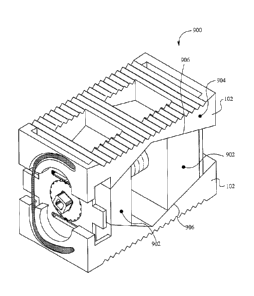
Figures 9A and 9B illustrate a retracted perspective view and an extended
perspective
view of a bodiless bone fusion device 900 having stretched or expanded
extending blocks
according to some embodiments. The bodiless bone fusion device 900 shown in
Figures 9A
and 9B is substantially similar to the bodiless bone fusion device 100 except
for the
differences described herein. Specifically, the sides 902 of the extending
blocks 106 shown
in Figures 9A and 9B extend such that the sides 902 substantially align with
the outer surface
of the device 900. As a result, the extending blocks 106 span the entire width
of the plates
102 which creates greater surface area for the blocks 106 to contact the
plates 102 as well as
greater stability in the extended position as a wider portion of the plates
102 is directly
contacted/supported by the blocks 106. In such embodiments, the skirt or sides
904 of the
plates 102 are able to comprise a block cavity 906 configured to receive the
sides 902 of the
blocks 106 when the device 900 is in the retracted position. Although as shown
in Figures
9A and 9B, both sides 902 of both blocks 106 are expanded to align with the
exterior surface
of the sides 904 of the plates 102, one or more of the sides 902 of one or
more of the blocks
106 are able to not be expanded and/or be expanded less. For example, one of
the sides 902
of one of the blocks 106 is able to extend part way into the cavity 906 on one
of the sides 904
of the plates 102.
Thus, the bodiless bone fusion device, apparatus and method described herein
has
numerous advantages. Specifically, the bodiless bone fusion device provides
the advantage
of maximizing the plate size to device size ratio because the size of the
plates is equal to the
size of the device in the retracted position creating a 1 to I ratio. This
enables the device to
incorporate larger plates that increase stability and surface area, which
would not be possible
with devices that incorporate a body. Also, the device provides the advantage
of the grip
channels that ensure the non-slippage of the driving mechanism during the
operation of the
bone fusion apparatus. Further, the position locking mechanism provides the
advantage of
reducing the chance of the positioning element unintentionally rotating and/or
the plates
unintentionally extending or retracting. Also, as mentioned above, the method
of use requires
18
only a small incision and minimally invasive surgical procedure advantageously
promoting
health and rapid recovery by the patient. Indeed, bone growth occurs around
the bodiless bone
fusion device and particularly at the locations of the extended plates, such
that the bodiless bone
fusion device is further secured by the bone growth, which further promotes a
superior, robust
bone fusion result. Moreover, the device provides the advantage of extending
blocks that span
the entire width of the plates thereby creating greater surface area for the
blocks to contact the
plates as well as providing greater stability in the extended position as a
wider portion of the
plates is directly contacted/supported by the blocks.
The present invention has been described in terms of specific embodiments
incorporating
details to facilitate the understanding of principles of construction and
operation of the invention.
It will be apparent to those skilled in the art that modification may be made
in the embodiments
chosen for illustration without departing from the spirit and scope of the
invention. For example,
it should be noted that although the above bodiless bone fusion devices are
described in
reference to a pair of extending blocks, a pair of screws, and wherein each
plate is shaped such
that the ends are larger than the middle, and the size of the plate gradually
increases while going
from the middle to the ends, the use of a single extending block in the above
embodiments is
contemplated. Specifically, if using a single extending block, the above
embodiments would
operate the same except the positioning element would comprise a single screw
that when
engaged would cause the single extending block to move from one end of the
screw to the other
end thereby exerting a force against the plates such that they move into the
extended position. In
such embodiments, each plate is shaped such that one end is larger than the
opposite end, and the
size of the plate gradually increases going from the smaller end to the larger
end.
19
CA 2906531 2019-08-12