Note: Descriptions are shown in the official language in which they were submitted.
CA 02906570 2015-09-14
WO 2014/160113
PCT/US2014/025847
A DIAGNOSTIC ASSEMBLY AND METHOD INCLUDING COLD
BARS FOR DETECTING A PRESENCE OF CANCER
CROSS REFERENCE TO RELATED APPLICATION
100011 This application claims the benefit of U.S. provisional
patent
application serial number 61/779,571 filed March 13, 2013, and entitled "Cold
Bar for FSM
Tester".
BACKGROUND OF THE INVENTION
1. Field of the Invention
[0002] A diagnostic assembly and method for detecting a presence of
cancer
in a breast of a patient.
2. Description of the Prior Art
[0003] It has been recognized in the field of cancer research and
treatment that
blood vessels that feed cancerous tumors in breasts, i.e. angiogenic blood
vessels, have a
different anatomical structure than normal blood vessels, causing such
angiogenic blood
vessels to constrict to a lesser degree than normal blood vessels in response
to a cold stimulus
that is applied to the body of a patient. As such, the temperature associated
with normal blood
vessels decreases to a greater extent than angiogenic blood vessels when the
body of the
patient is exposed to the cold stimulus.
[0004] In recognition of this difference, a method called a "cold
challenge"
has been developed to detect the presence of breast cancer in patients,
wherein thermal
images of the breasts of the patient are recorded before and after the hands
of the patient are
subject to a cold stimulus. The second thermal image, i.e. a test thermal
image, taken after the
hands of the patient are subject to the cold stimulus, is compared to the
first thermal image,
i.e. a control theiiiial image, taken before the hands of the patient are
subject to the cold
1
CA 02906570 2015-09-14
WO 2014/160113
PCT/US2014/025847
stimulus to identify regions of the breasts in which the temperature remained
substantially
unchanged after the patient was subjected to the cold stimulus, therefore
indicating the
presence of angiogenic blood vessels and cancer in the regions.
[0005] One example of such a cold challenge assembly and method is
disclosed in U.S. Patent 7,558,618 to Darin S. Williams including a frame
supporting a
bucket of ice water, wherein thermal images of the breasts of the patient are
recorded before
and after the hands of the patient are cooled by dipping the hands of the
patient in the bucket
of ice water.
[0006] Such prior art cold challenges suffer from certain
drawbacks. One such
drawback is that the ice water tends to be heated by the hands of the patient
during
administration of the tests, especially at the boundary layer of the ice water
around the
patient's hands and fingers. Additionally, the temperature of the ice water
can vary as it sits
between and during the administration of tests. Such variances in the
temperature of the ice
water during and between administration of tests can lead to imprecise and
inconsistent test
results. Additionally, certain patients are sensitive to the cold, such as
those with Renaud's
Syndrome, and can become uncomfortable during testing. Further, such ice
buckets are prone
to spilling during administration of the test and during movement between
tests. Thus, a nurse
or technician is required to clean up and maintain the ice buckets during and
after each test.
SUMMARY OF THE INVENTION
[0007] The invention provides for a diagnostic assembly including
at least one
cold bar supported by the frame for receiving a hand of the patient, and a
temperature
controller in communication with the cold bar to maintain a constant
temperature of the cold
bar during the test.
[0008] The invention further provides for a method of detecting a
presence of
cancer wherein the step of cooling the hand of the patient further includes
receiving the hand
2
CA 02906570 2015-09-14
WO 2014/160113
PCT/US2014/025847
of the patient on a cold bar to transfer heat from the hand of the patient to
the cold bar, and
maintaining the cold bar at a preselected temperature during the step of
cooling the hand of
the patient.
ADVANTAGES OF THE INVENTION
[0009] Several advantages of one or more aspects of the invention
are that
more consistent and precise testing results are produced because the cold bar
is maintained at
a consistent temperature during and between administration of tests.
Additionally, patients
with various medical backgrounds are able to remain comfortable during testing
as the cold
bar is capable of being maintained at a range of different temperatures.
Furthermore, the
administration of tests is advantageously a clean process as compared to prior
testing
methods, as no fluids are used during testing and therefore there is no risk
of splashing of
fluids during and between the administration of tests.
BRIEF DESCRIPTION OF THE DRAWINGS
[0010] Other advantages of the present invention will be readily
appreciated,
as the same becomes better understood by reference to the following detailed
description
when considered in connection with the accompanying drawings wherein:
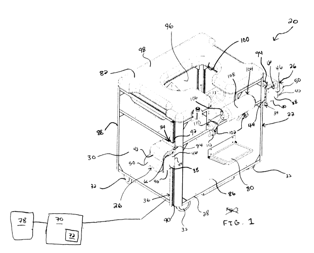
[0011] Figure 1 is a perspective view of a first enabling
embodiment of a
diagnostic assembly for detecting a presence of cancer in a breast of a
patient;
[0012] Figure 2 is a perspective view of a first enabling
embodiment of a cold
bar;
[0013] Figure 3 is a cutaway side view of the first enabling
embodiment of the
cold bar;
100141 Figure 4 is a perspective front view of a second enabling
embodiment
of the diagnostic assembly;
3
CA 02906570 2015-09-14
WO 2014/160113
PCT/US2014/025847
[0015] Figure 5 is a perspective back view of the second enabling
embodiment of the diagnostic assembly;
[00161 Figure 6 is a cutaway back view of the second enabling
embodiment of
the diagnostic assembly presenting tracks and a lead screw for vertically
moving a pair of
cold bars;
100171 Figure 7 is a perspective view of a second enabling
embodiment of the
cold bar illustrating a pommel having a generally spherical shape;
[00181 Figure 8 is a perspective view of a third enabling embodiment
of the
cold bar illustrating the pommel defining a plurality of indentations for
receiving the fingers
of a patient;
100191 Figure 9 is a perspective view of the second enabling
embodiment of
the diagnostic assembly illustrating a patient gripping the cold bars; and
100201 Figure 10 is a flowchart a method for detecting a presence of
cancer in
breasts of a patient.
DETAILED DESCRIPTION OF THE ENABLING EMBODIMENTS
100211 Referring to the figures, wherein like numerals indicate
corresponding
parts throughout the several views, a diagnostic assembly 20, 320 is generally
shown for
detecting a presence of cancer in a patient. The diagnostic assembly 20, 320
includes a frame
22, 322, generally indicated, for supporting the assembly 20, 320. A
thennographic camera
mechanism 324 is connected with the frame 22, 322 for recording thermal images
of the
breasts of the patient during testing with the assembly 20, 320. At least one
cold bar 26, 326,
426, generally indicated, is connected with the frame 22, 322 for being
received and gripped
by the hands of the patient to cool the hands of the patient. As explained in
greater detail
below, the thermographic camera mechanism 324 is configured to record three
dimensional
thermal images of the breasts of the patient before and after the patient's
hands are cooled by
4
CA 02906570 2015-09-14
WO 2014/160113 PCT/US2014/025847
the cold bars 26, 326, 426, and the images are compared to one another to
identify the
presence of angiogenic blood vessels and cancerous regions of the breasts.
[0022] The frame 22, 322 includes a base 28, 328 and a pair of
sidewalls 30,
330 that extend perpendicularly from said base 28, 328. A plurality of casters
32 are
connected to the base 28, 328 for establishing rolling movement of the
diagnostic assembly
20, 320 over a floor in an examination room. The frame 22, 322 further
includes a carrier 34,
334, generally indicated, that is moveably connected with the base 28, 328.
More specifically,
a track 36, 336, generally indicated, extends perpendicularly to and away from
the base 28,
328, and the carrier 34, 334 is slideably disposed on the track 36, 336 to
interconnect the
frame 22, 322 and carrier 34, 334 and to provide for vertical linear movement
of the carrier
34, 334 along the track 36, 336.
[0023] At least one cold bar 26, 326, 426 is connected with the
carrier 34, 334
for cooling the hands of a patient during testing with the assembly 20, 320.
As best presented
in Figures 2 and 4, in the preferred embodiments, the at least once cold bar
26, 326, 426
includes a pair of cold bars 26, 326, 426 extending from the carrier 34, 334.
As also presented
in Figures 2, 3 and 7, each of the cold bars 26, 326, 426 includes a chassis
38, 338 that has a
generally box shape. The chassis 38, 338 has a lower face 40, a frontward face
42 and a
rearward face 44, a pair of side faces 46 that extend from the lower face 40,
and a
compartment 48 defined between the faces 40, 42, 44, 46. It should be
appreciated that the
chassis 38 could have other shapes such as, but not limited to, a spherical or
ovoid shape.
[0024] The cold bars 26, 326, 426 each further include a pommel 50,
350, 450
of an aluminum material that is connected with the frontward face 42 of the
chassis 38, 338
for being received and gripped by the hands of the patient. Each of the
pommels 50, 350, 450
are spaced from the frame 22, 322, advantageously ensuring that that patient's
arms are
spaced from their breasts to prevent heating of the breasts by the arms during
testing. As a
CA 02906570 2015-09-14
WO 2014/160113 PCT/US2014/025847
result, the forced spacing of the patient's arms from the breasts prevents
inaccurate and
inconsistent measurements of the temperature of the breasts. It should be
appreciated that the
pommels 50, 350, 450 could be spaced from the frame 22, 322 at various
distances as
required to accommodate patients of various heights and having different arm
lengths.
[0025] As best presented in Figure 3, the pommel 50, 350, 450 and
the
frontward face 42 of each of the chassis' 38, 338 define a passage 54 that
extends to the
compartment 48 of the chassis 38, 338. A cooling element 56 is disposed in the
passage 54 in
each of the pommels 50, 350, 450 for adjusting the temperature of the outer
surface of the
pommel 50, 350, 450. In the enabling embodiments, the cooling element 56 is of
the pettier
semiconductor type, i.e. a thermographic cooler, but it should be appreciated
that other types
of coolers could be used such as, but not limited to, a conventional
refrigeration cycle. It
should be appreciated that the cooling element 56 could extend across the
length of the
pommel 50, 350, 450 to ensure that the pommel 50, 350, 450 is evenly cooled
across the
length of the pommel 50, 350, 450. Alternatively, it should be appreciated
that a plurality of
cooling elements 56 could be placed at any area along the length of the pommel
50, 350, 450
to ensure that the pommel 50, 350, 450 is evenly cooled across the length of
the pommel 50,
350, 450.
[0026] A heat sink 58 is disposed in the compartment 48 of each
chassis 38,
338 adjacent to the cooling element 56 for directing heat produced by the
cooling element 56
away from the cooling element 56. A pair of bolts 60 threadedly connect the
pommel 50, 350,
450 and the heat sink 58 to sandwich the frontward face 42 of the chassis 38
between the
pommel 50, 350, 450 and the heat sink 58 to secure the pommel 50, 350, 450,
chassis 38, and
heat sink 58 to one another. It should be appreciated that the pommel 50, 350,
450, chassis
38, and heat sink 58 could be fastened together in other ways such as, but not
limited, through
the use of screws or adhesives.
6
CA 02906570 2015-09-14
WO 2014/160113 PCT/US2014/025847
[0027] The lower face 40 of each chassis' 38, 338 defines a
plurality of
exhaust outlets 62 for allowing air that has been heated by the heat sink 58
to escape from the
compartment 48. The exhaust outlets 62 of the chassis 38, 338 are
advantageously pointed
away from the pommels 50, 350, 450 to prevent heated air from blowing on the
patient and
the pommels 50, 350, 450. It should be appreciated that any number of exhaust
outlets 62
could be present and they could be defined by other areas of the chassis 38,
338, but they
should not be oriented toward the patient or pommels 50, 350, 450. A fan 64 is
disposed in
the compartment 48 adjacent to the heat sync for directing air that has been
heated by the heat
sink 58 out of the exhaust outlets 62. The side faces 46 of the chassis 38
each define an air
inlet 66 for allowing ambient air to enter the compartment 48. It should be
appreciated that
any number of air inlets 66 could be defined by the chassis 38, 338 and they
could be defined
by other areas of the chassis 38, 338.
100281 A controller 70 is connected with the assembly 20, 320 for
controlling
the assembly 20, 320 during administration of tests. The controller 70
includes a computer
(not shown) that is connected with the frame 22, 322. It should be appreciated
that the
computer could be disposed inside or outside of the frame 22, 322 and can
control various
aspects of the assembly 20. The controller 70 includes a temperature
controller 72 that is
connected with the cooling element 56 to control the temperature of the
pommels 50, 350,
450 of the cold bars 26, 326, 426. As best shown in Figure 3, the temperature
controller 72
includes a circuit board 74 that is disposed in the compartment 48 and
electrically connected
with the cooling element 56. A sensor 76 engages each of the pommels 50, 350,
450 for
reading the temperature of the outer surface of the pommels 50, 350, 450 and
transmitting
temperature data. In the enabling embodiments, the sensor 76 is a thermistor,
but it should be
appreciated that other temperature sensors 76 could be used such as, but not
limited to, a
conventional resistance thermometer. The temperature controller 72 is
electrically connected
7
CA 02906570 2015-09-14
WO 2014/160113
PCT/US2014/025847
with the sensor 76 for receiving temperature data from the sensor 76 to allow
the controller
70 to maintain a constant temperature of the outer surface of each of said
pommels 50.
Accordingly, a feedback based closed loop temperature regulator circuit is
used to monitor
and maintain a constant temperature. However, it should be appreciated that
other circuits
could be used to maintain the temperature of the pommels 50, 350, 450.
Accordingly, it
should be appreciated that the assembly 20, 320 advantageously provides for
consistent
testing results because the cold bars 26, 326, 426 are maintained at a
consistent temperature
during and between administrations of tests.
[0029] As best shown in Figures 1 and 4, a power source 78 is
electrically
connected with the cooling element 56, the temperature controller 72, and the
sensor 76 for
powering the cooling element 56, sensor 76 temperature controller 72. It
should be
appreciated that the power source 78 could be various types of batteries or a
connection to a
power outlet in a wall.
[0030] The thermographic camera mechanism 324 is connected with the
carrier 34, 334 for measuring the temperature of the patient's breasts while
the pommels 50,
350, 450 receive the gripped hands of the patient. The thermographic camera
mechanism 324
is electrically connected with the power source 78 and the controller 70 for
powering and
controlling the thermographic camera mechanism 324.
[0031] A graphical user interface 80, 82 that has a rectangular
shape is
connected with the frame 22, 322 and is in data connection with the controller
70 for
receiving and presenting operational data related to the assembly 20, 320 to
the physician or
patient. The graphical user interface, 80, 82 is electrically connected with
the power source
78 for powering the graphical user interface. It should be appreciated that
the graphical user
interface could be various types of conventional interfaces such as, but not
limited to, a
conventional LCD monitor or cathode ray tube monitor. In the enabling
embodiments, the
8
CA 02906570 2015-09-14
WO 2014/160113
PCT/US2014/025847
graphical user interface 80, 82 is of the touch-screen type for receiving
commands from the
patient during administration of the exam and therefore the commands are
transmitted to the
controller 70 to adjust various parameters of the assembly 20, 320 such as the
vertical height
and temperature of the cold bars 26, 326, 426.
[0032] In the first enabling embodiment of the diagnostic assembly
20, as best
presented in Figure I, the frame 22 further includes a top 84, a front wall
86, a rear wall 88,
and the pair of sidewalls 30. The track 36 includes a pair of tracks 36 that
each extend along
one of the sidewalls 30 between the top 84 and the base 28 of the frame 22.
Each of the tracks
36 defines a pair of slots 90 that extend therein in spaced and parallel
relationship with one
another and linearly along the track 36.
[0033] The carrier 34 includes a pair of carriers 34 that each have
a generally
U-shaped cross section and partially surround one of the tracks 36. The
carriers 34 each
include a pair of projections 92 that are each slideably disposed in one of
the slots 90 of the
track 36 for allowing the vertical movement of the carrier 34 and the cold bar
26 along the
track 36, and for preventing outward movement of the carrier 34 and the cold
bars 26 relative
to the track 36. A pin 94 slideably extends through each carrier 34 for
engaging one of the
tracks 36 to lock the carrier 34 and the cold bars 26 in a predetermined
vertical location along
the track 36. Accordingly, a physician is able to slide the carriers 34 and
cold bars 26 along
the tracks 36 to a location that suits the height and arm length of the
patient, and then lock the
carrier 34 in place using the pin 94.
[0034] The frame 22 defines a chamber 96 between the top 84, base
28, front
wall 86, rear wall 88 and sidewalls 30. The top 84 is defined by a padding
layer 98 for
allowing a patient to comfortably lie along the top 84 of the frame 22. It
should be
appreciated that the padding could be made of various materials such as, but
not limited to, a
foam material. The top 84 further defines an opening 100 that extends to the
chamber 96 for
9
CA 02906570 2015-09-14
WO 2014/160113
PCT/US2014/025847
receiving the breasts of the patient. The thermographic camera mechanism (not
expressly
shown) is disposed inside the frame 22.
100351 A pair of flanges 102 that have a rectangular shape extend
away from
the front wall 86 of the frame 22 in spaced and parallel relationship with one
another. A head
rest 104 is connected with and spaced from the flanges 102 of the frame 22 for
receiving the
head of a patient lying along the top 84 of the frame 22. The head rest 104
includes an inner
cylinder 106 that has a tube shape, and a cushion 108 that has a tube shape
disposed about the
inner cylinder 106. A pair of rods 110 are each pivotally connected with one
of the flanges
102 and the head rest 104 for facilitating a pivoting movement of the head
rest 104 toward
and away from the front wall 86 of the frame 22 relative to the flanges 102. A
pair of
fasteners 112 each threadedly extend through one of the flanges 102 and one of
the rods 110
for tightening the head rest 104 in a fixed position. Accordingly, a physician
may pivot and
secure the head rest 104 to a position that is comfortable for the patient
while they lie along
the top 84 of the frame 22. It should be appreciated that the head rest 104
could be of other
types such as, but not limited to, a member that extends away from the front
wall 86 of the
frame 22.
100361 The graphical user interface 80 includes a first graphical
user interface
80 that extends perpendicularly from the front wall 86 and is spaced from the
flanges 102
toward the bottom such that it may be used to present and receive operational
data to and
from the patient while the patient is lying along the top 84 of the frame 22.
Further, the
rearward face 44 of each of the chassis 38 is connected with the carrier 34 to
provide for
movement of the cold bars 26 along the track 36.
[0037] In the second enabling embodiment of the diagnostic assembly
320 as
best presented in Figures 4-6, the assembly 320 further includes a plurality
of legs 114 that
each have a terminal end 116 and extend outwardly from the base 328 of the
frame 322 to the
CA 02906570 2015-09-14
WO 2014/160113
PCT/US2014/025847
terminal end 116. One of the casters 32 is connected to each of the legs 114
adjacent to the
terminal end 116. It should be appreciated that any number of legs 114 could
be used and that
the legs 114 could extend to various lengths.
[0038] Further, the track 336 includes a pair of beams 336 that
extend
perpendicularly from the base 28 of the frame 22 in spaced and parallel
relationship with one
another. The carrier 334 includes a case 335 that has a generally cuboid shape
and has a
bottom periphery 118, front periphery 120, a rear periphery 122, and a pair of
side peripheries
124 extending between the bottom, front, and rear peripheries 118, 120, 122.
The bottom
periphery 118 defines a channel 126 that extends therein and telescopically
receives the
beams 336 to provide for vertical and linear movement of the case 335 along
the beams 336.
[0039] The carrier 334 further includes a handle 128, generally
indicated, that
has a ring-shaped cross-section and extends about the case 335. The handle 128
includes a
front section 130 that engages the front periphery 120 of the case 335, a rear
section 132 that
is spaced from the rear periphery 122 of the case 335, and a pair of side
sections 134 that are
each spaced from one of the side peripheries 124 of the case 335. The handle
128 defines a
hollow that extends therethrough. The front section 130 of the handle 128 has
a U-shape that
extends along a pair of limbs 352 toward the front face of the support. The
rearward face 44
of each of the cold bars 326 engages one of the limbs 352 of the front section
130 of the
handle 128 to space the pommels 350 from the case 335. It should be
appreciated that the
handle 128 advantageously serves as a grip for allowing a physician or patient
to move the
assembly 320, as a support for the cold bars 326, and as a bumper for
protecting the assembly
320 during movement of the assembly 320.
(0040] The graphical user interface 80, 82 includes a first
graphical user
interface 80 that is connected with the front periphery 120 of the case 335
and a second
graphical user interface 82 that is connected with the rear periphery 122 of
the case 335.
11
CA 02906570 2015-09-14
WO 2014/160113
PCT/US2014/025847
Accordingly, it should be appreciated that a patient and physician could each
receive and
input data during administration of an exam at the same time through the first
and second
graphical user interfaces 80, 82.
[0041] The thermogaphic camera mechanism 324 is connected with the
front
periphery 120 of the case 335 and is spaced from the first graphical user
interface 80 toward
the bottom periphery 118 for taking thermogaphic images of the breasts of the
patient.
[0042] As best presented in Figure 6, a lead screw 136 that is
threaded is
rotatably connected with and extends perpendicularly from the base 328 between
the beams
336. A driving motor 138 engages the base 328. The driving motor 138 includes
a piston 140
that is rotatably connected with the lead screw 136 for providing rotary
motion of the lead
screw 136. A belt 142 is disposed about the piston 140 of the driving motor
138 and the lead
screw 136 for transferring rotating movement of the piston 140 to the lead
screw 136.
[0043] The case 335 includes a cross-member 144 that has a cuboid
shape and
extends transversely between the side peripheries 124 at the bottom periphery
118 of the case
335. The lead screw 136 threadedly extends through the cross-member 144 for
converting
rotary motion of the lead screw 136 into vertical and linear motion of the
cross-member 144
along the lead screw 136 to provide for vertical and linear movement of the
carrier 334. It
should be appreciated that the case 335 could have other shapes such as, but
not limited to an
ovoid shape.
[0044] The controller 70 is further in data communication with the
driving
motor 138 for controlling the driving motor 138 to control the vertical and
linear movement
of the carrier 34. The power source 78 is further electrically connected with
the driving motor
138 for powering the driving motor 138.
[0045] As best presented in Figure 4, a power container 146 that
has a
rectangular shape is connected to the frame 322 adjacent to the front
periphery 120 of the
12
CA 02906570 2015-09-14
WO 2014/160113
PCT/US2014/025847
case 335. A pair of hooks 148 extend from the power container 146 in spaced
and parallel
relationship with one another for receiving a wrapped power cable. The power
source 78
includes a pair of power sockets 150 that are defined by the power container
146 for
electrically connecting the assembly 320 with a wall socket. The power source
78 further
includes a backup battery 152 that engages the case 335 and is electrically
connected with the
controller 70, cold bars 26, and the thermographic camera mechanism 324 for
providing for
backup power of the controller 79, cold bars 26, and the thermographic camera
mechanism
324.
100461 In the first and second enabling embodiments of the cold bar
26, 326,
426, the pommels 50 have a generally cylindrical shape. However, it should be
appreciated
that the pommels 50 could have other shapes to increase the surface area of
the pommels 50
while they receive gripped hands of the patient and to make the pommels 50
more
comfortable to grip. In a further enabling embodiment of the pommels 350 as
best presented
in Figure 7, each of the pommels 350 has a generally spherical shape. As best
presented in
Figure 8, each of the pommels 50, 350, 450 could further define a plurality of
indentations for
receiving individual fingers of the patient to increase the surface area of
the pommels 50,
350, 450 that is received by the gripped hand of the patient.
[0047] As best presented in Figure 10, a method for detecting a
presence of
cancer in breasts of a patient using at least one cold bar 26, 326, 426 is
also disclosed. The
method comprises the step of 154 recording a control thermal image of the
breasts of the
patient using the thermographic camera mechanism 324. In the enabling
embodiment, the
control thermal image is a three-dimensional image, however, it should be
appreciated that a
two-dimensional thermal image could also be recorded by the thermographic
camera
mechanism 324. The control thermal image is recorded prior to cooling of the
hands of the
13
CA 02906570 2015-09-14
WO 2014/160113
PCT/US2014/025847
patient to establish a thermal image of the breasts of the patient in a state
in which a cold
stimulus has not been applied to the patient.
[0048] The method proceeds by 156 moving the cold bars 26, 326, 426
vertically to a vertical position to accommodate for the height and arm length
of the patient to
provide for increased comfort of the patient and to maintain the arms of the
patient in a
position spaced from the breasts of the patient. In the enabling embodiments,
the cold bars
26, 326, 426 are moved vertically by sliding the carrier 34, 334 along the
track 36, 336, but it
should be appreciated that the cold bars 26, 326, 426 could be moved in other
ways such as,
but not limited to, by placing the cold bars, 26, 326 on a table or other
surface that is
positioned at a desired vertical position. It should also be appreciated that
while moving the
cold bars 26, 326, 426 vertically to a vertical position, the arms of the
patient should also be
spaced horizontally from the breasts of the patient. Accordingly, the arms of
the patient are
spaced from the breasts of the patient prior to recording both the control and
test thermal
images to prevent inaccurate test results.
[0049] The method proceeds by 158 setting the cold bars 26, 326,
426 to be
cooled to a preselected temperature. It is advantageous that the cold bars 26,
326, 426 can be
set to various temperatures to maintain comfort of patients with different
medical
backgrounds during administration of the test. For most patients, the
preselected temperature
is in the range between 10 and 12 degrees Celsius (50 to 53.6 degrees
Fahrenheit). However,
it should be appreciated that a warmer preselected temperature can be chosen
for patients
with certain medical backgrounds. For example, patients with Renaud's syndrome
who are
sensitive to cold temperatures can undergo testing at a higher temperature,
like 17 degrees
Celsius (62.6 degrees Fahrenheit).
[0050] The method then proceeds by 160 cooling the hands of the
patient.
More specifically, as best presented in Figure 8, the hands of the patient are
cooled by
14
CA 02906570 2015-09-14
WO 2014/160113
PCT/US2014/025847
respectively receiving gripped hands of the patient on the cold bars 26, 326,
426 to transfer
heat from the hands of the patient to the cold bars 26, 326, 426.
[0051] Additionally, the method includes the step of 162
maintaining the cold
bars 26, 326, 426 at the preselected temperature during the step of cooling
the hands of the
patient. The step of 162 maintaining the cold bars 26, 326, 426 at the
preselected temperature
includes the step of 164 sensing the temperature of the cold bars 26, 326, 426
during the
transferring of heat from the hands of the patient to the cold bars 26, 326,
426 and the step of
166 extracting heat from the cold bars 26, 326, 426 in response to the sensed
temperature of
the cold bars 26, 326, 426.
[0052] After the hands of the patient have been cooled, the method
proceeds
by 168 recording a test thermal image of the breasts of the patient to capture
temperature
changes in regions of the breasts of the patient in response to cooling of the
hands of the
patient.
[0053] The method also includes the step of 170 comparing the test
thermal
image to the control thermal image to identify regions of the breasts in which
the temperature
remained substantially unchanged after the hands of the patient were cooled
indicating the
presence of angiogenic blood vessels and cancer in the regions. Typically
regions that have
dropped approximately 0.2 degrees Fahrenheit are identified as indicators of
breast cancer,
however other temperature changes could be identified.
[0054] Obviously, many modifications and variations of the present
invention
are possible in light of the above teachings and may be practiced otherwise
than as
specifically described while within the scope of the appended claims. That
which is prior art
in the claims precedes the novelty set forth in the "characterized by" clause.
The novelty is
meant to be particularly and distinctly recited in the "characterized by"
clause whereas the
antecedent recitations merely set forth the old and well-known combination in
which the
CA 02906570 2015-09-14
WO 2014/160113
PCT/US2014/025847
invention resides. These antecedent recitations should be interpreted to cover
any
combination in which the inventive novelty exercises its utility. The use of
the word "said"
in the apparatus claims refers to an antecedent that is a positive recitation
meant to be
included in the coverage of the claims whereas the word "the" precedes a word
not meant to
be included in the coverage of the claims. In addition, the reference numerals
in the claims
are merely for convenience and are not to be read in any way as limiting.
16