Note: Descriptions are shown in the official language in which they were submitted.
CA 02906590 2015-09-14
WO 2014/152765 PCT/US2014/027708
INTERFACE FOR RENEWABLE ENERGY SYSTEM
BACKGROUND OF THE INVENTION
Field of the Invennoii
This invention relates to solar energy and more particularly to an improved
interface for
renewable energy systems such as photovoltaic saar panels and the like.
Description of the Related Art
The utilization of solar energy extends back to .the 7th century B.C.., where
a magnifying
1...-lass was used to make fire. Since then, the evolution of solar technology
has progressed from
strictly solar to thermal conversion .si.,,stems to the discovers' of the
photovoltaic effect in the
1800's.
Advancement of the photovoltaic art continued to progress, and in the 1950's
the
development of the silicon photovoltaic (PV) cell became the lust solar cell
capable of producing
sufficient power to run simple electrical equipment. In 1964 NASA launched the
first 'Nimbus
spacecraft, which was powered by a 470 watt .photovoltaic array. In 1981 the
first solar powered
aircraft had solar cells capable of producing 3,000 waits. In 1983 a stand
alone 4 kilowatt
powered home was completed. By 1999, the cumulative worldwide installed
photovoltaic
capacity reached 1,000 megawatts,
The future of RV technology is expected to produce photovoltaic power to be
competitive
with traditional power generation sources within 10 years. in order to move
toward this goal the
cost per watt must be minimized. This requires all elements of a solar power
system to consider
both cost and system energy requirements. Since solar power systems comprise
several key
components in addition to the PV cell, development of these components also
affects the evolution
of the entire solar power system.
Solar panels may be roof mounted on racks and ground mounted with fixed racks
which
are held stationary as the sun moves across the sky. In other installations,
solar trackers sense the
direction of the sun and move of tilt the panels to maximize the energy
produced per panel. When
employing solar tracking systems, overall weight arid weight distribution
become necessary
considerations which affect system energy requirements.
CA 02906590 2015-09-14
WO 2014/152765 PCT/US2014/027708
In order to produce power useable for most purposes, the direct current (DC)
produced by
the PV cell must be converted to alternating current (AC) having the frequency
of the local utility.
This conversion is accomplished by an inverter. A stand alone inverter is
used. in totally isolated
systems that normally do not interface with the utility grid. More
sophisticated inverters convert
the =DC to AC at the 'utility frequency and. ensure maintaining the AC
inverter output in phase with.
.the .utility grid AC phase. Additionally, these inverters must be provided
with an anti-islanding
feature which will ensure that the inverter switches off upon the. loss of
grid AC power.
An inverter dedicated to a single solar cell panel is called a. micro-
inverter. Typically,
micro-inverters are mounted to the: back of solar cell panel. The weight and
placement of the
micro-inverter must be considered in the overall system design. Solar panels
with enabled solar
tracking require power to move or tilt the panel. Therefore overall weight as
well as weight
distribution about the center of gravity of the system must be considered in
order to minimize the
energy required -to operate the system. Additionally, the heat generated by
the 'micro-inverters
operation must be considered in the design of a photovoltaic system. 'Excess
heat may cause
is damage
to both the micro-inverter as well as the solar panel itself. Finally, the
micro-inverter must
be easily adapted to mounting on solar panels having varying widths.
There have been many in the prior art who have attempted to solve these
problems with
varying degrees of success. The following US patents and publications are
examples of attempts
in the prior art to provide an efficient micro-inverter system tbr a
photovoltaic array.
US Patent 8,410,950 to Takehara et al. discloses a photovoltaic (PV) panel
monitoring
apparatus including a monitoring module for measuring parameter values related
to PV .panel
output, comparing measured values against minimum and maximum values saved in
the
monitoring module and outputting an alarm signal when a measured value is
outside a range
defined by the minimuni and maximum values.. An alarm signal causes a visual.
indicator to
activate and an audible indicator to sound, thereby assisting maintenance
personnel in locating a
PV panel with an out-of-range parameter value. The 'monitoring module: further
includes a 'PV
panel identification memory for saving an identification code for each PV
panel in a PV array. The
identification code is transmitted with time, date, and parameter data when
the monitoring module
detects an out-of-range parameter value. Data. may optionally be transmitted
from the monitoring
.30 module
through a communications input/output port or through a wireless transmitter
to an
external monitoring and control system.
2
CA 02906590 2015-09-14
WO 2014/152765 PCT/US2014/027708
US Patent 89106,537 to Casey: et al discloses a photo-voltaic (PV) power
generating
system and a control system for PV array string-level control and PV modules
sedally-connected
into strings of PV modules. The system includes plural parallel strings of
serially-connected
power-generating photovoltaic modules that form a PV array, DC/DC micro-
converters that are
coupled to a DC voltage buss and to the output of a corresponding photovoltaic
module or to the
output of a string of photovoltaic modules, a gating or central inverter, and
a control system. The
control system is structured and arranged to control and manage each string of
photovoltaic
modules, to ensure that power delivered by the photovoltaic power generating
system is not
affected by photovoltaic :modules or strings of photovoltaic modules that are
not operating at:
0 maximum power transfer efficiency.
US Patent publication 20120313443 to Chem?, discloses a method and apparatus
for
intelligently inverting DC power from DC sources such as photovoltaic (PV)
solar modules to
single-phase or three-phase AC power to supply power tor off-grid
applications. A. number of
regular or redundant off-grid Mini-Inverters with one, two, three, or multi*
input channels in a
is mixed variety can easily connect to one, two, three, or multiple DC
power sources such as solar
PV modules, invert the DC power to AC power, and daisy Chain together to
generate and supply
AC power to electrical devices that are not connected to the power grid
including motors, pumps,
fans, lights., appliances, and homes.
US Patent publication 20130012061 to Rotzoll et al., discloses a replaceable
photovoltaic
20 inverter mounted on each of a plurality of photovoltaic module for the
conversion of direct current
produced by the photovoltaic cells, to alternating current The inverter is
coupled to a mounting
bracket on the photovoltaic module such that it can be easily replaced.
'Replacement of an
individual photovoltaic module inverter can occur during continuous operation
of the photovoltaic
module system with minimal impact on overall power production. The inverter is
also mounted
25 apart from the photovoltaic module to facilitate heat transfer generated
by operation of the
inverter,
US Patent publication 20130002031 in Mulkey et al. discloses an enclosure
design to
accommodate and support the unique features and capabilities of the smart and
scalable power
inverters or mini-inverters that have multiple input channels to easily
connect to multiple solar PV
.30 panels, invert the DC power to AC power, and. daisy chain together to
generate AC power to feed
the power grid or supply power to electrical devices. Further disclosed is a
message system using
LEDs (light-emitting diodes) mounted on the enclosure to indicate the system
status and the status
of each input channel of the Smart and Scalable Mini-Inverters,
3
CA 02906590 2015-09-14
WO 2014/152765 PCT/US2014/027708
Unfortunately., none of the preceding prior art has completely satisfied the
requirements for
a complete solution to the aforesta,ted problem.
Therefore, it is an Object of the present invention to provide an improved
interface for
renewable energy system that is a significant advancement in the solar
generatini4 electrical art
Another object of this invention is to provide an improved interface for
renewable energy
system incorporating a micro-inverter having an improved heat dissipating
system.
Another object of this invention is to provide an improved interface for
renewable energy
system incorporating an, improved, mounting system for a photovoltaic solar
array.
Another object of this invention is to provide an improved interface for
renewable energy
system incorporating an improved remote monitoring system.
Another object of this invention is to provide an improved interface for
renewable energy
system capable of a grid tied operation, off grid operation and emergency
power operation.
Another object of this invention is to provide an improved interface for
renewable energy
system incorporating an automatic transfer switch for automatically switching
between a grid tied
operation, an off grid operation and an emergency power operation.
Another object of this invention is to provide an improved interface for
renewable energy
system incorporating a multi-channel micro-inverter with each of the micro-
inverters operating
independently of the remaining micro-inverters.
Another object of this invention is to provide an improved interface for
renewable energy
system incorporating a multi-channel micro-inverter incorporating a controller
for monitoring and
instructing each of the micro-inverters and a redundant power supply for the
controller.
Another object of this invention is to provide an improved interface for
renewable energy
system incorporating that is readily mountable on a variety of renewable
energy sources such as
photovoltaic solar array, windmills, fuel cells and the like.
Another object of this invention is to provide an improved renewable energy
system that is
easy to cost effectively produce.
Another object of this invention is to provide an improved renewable energy
system .that is
easy to install and maintain.
Another object of this invention is to provide an improved renewable energy
system
.30 incorporating an apparatus for identifying a performance and/or fault
in a solar panel of a solar
panel array,.
The foregoing has outlined some of the more pertinent objects of the present
invention.
These objects should be construed as being merely illustrative of some of the
more prominent
4
CA 02906590 2015-09-14
WO 2014/152765 PCT/US2014/027708
features and applications of the invention, Many other beneficial results can
be obtained by
applying using the disclosed invention in a different manner or modifying the
invention.
Accordingly other objects in a full understanding of .the invention may be had
by referring to the
summary of the invention and the detailed description describing the preferred
embodiment of the
invention,
SUMMARY OF THE INVENTION
The present invention is defined by the appended claims with sped tic
embodiments being
shown in the attached drawings.. For the purpose of summarizing the invention,
the invention
relates to an improved multi-channel micro-inverter for a plurality of
photovoltaic solar panels
comprising a container extending between a first and a second end, An AC power
bus is disposed
in the container having a plurally of input AC power bus connectors and a
plurally of input data
bus connectors. An AC bus output is connected to the AC bus tbr connecting AC
power and
electronic data external the container. A plurality of micro-inverter circuits
each have a micro
-
inverter DC power input and an AC power output connector and a. micro-inverter
data connector.
A DC power connector connects each of the plurality of micro-inverter circuits
to the plurality of
photovoltaic solar panels, respectively. The plurality of micro-inverter
circuits are insertable
within the container with the micro-inverter AC power output connector
engaging with one of the
input .AC power bus connectors and with the micro-inverter data connector
engaging with one of
the plurality of input data bus connectors.
In another embodiment of the invention, the invention is incorporated into an
improved
mounting for a tnicro-in verter for a photovoltaic solar panel having a
peripheral frame comprising
a micro-inverter circuit board comprisinp, a micro-inverter circuit having a
power stage. A
container extends between a first and a second end for receiving the micro-
inverter .circuit board
therein. A closure seals with the container. A mounting secures the micro-
inverter circuit board
within .the container with .the power stage thermally coupled to one of the
container and the
closure. .A plurality of mounting arms mount the otos= to .the pefipheral
frame of the solar panel
for transferring heat 17romi the micro-inverter circuit board to the
peripheral frame of the solar
.30 panel.
In another embodiment of the invention, the invention is incorporated into an
improved
mounting for a Micro-inverter for a photovoltaic solar panel having a
peripheral frame comprising
a micro-inverter circuit board comprising a micro-inverter circuit having a
power stage. A
5
CA 02906590 2015-09-14
WO 2014/152765 PCT/US2014/027708
container extends between a first and a second end for receiving the micro-
inverter circuit board
therein. A closure seals with the container. A mounting secures the micro-
inverter circuit board
within .the container with the power stage thermally coupled to one of the
container and the
closure. A plurality of mounting arms mount the closure to the peripheral
frame of the solar panel
for transferring heat fromi the micro-inverter circuit board to the peripheral
frame of the solar
panel. A thermal transfer medium is interposed between the power stage and one
of the container
and the closure .for thermally coupling the power stage to the one of the
container and the closure.
In another embodiment of the invention, the invention is incorporated into an
improved
mounting ter a micro-inverter for a photovoltaic solar panel having a
peripheral frame comprising
a .micro-inverter circuit board comprising a micro-inverter circuit having a
power stage. A
container extends between a first and a second end for receiving the micro-
inverter circuit board
therein. A closure seals with the container. A mounting secures the micro-
inverter circuit board
within the container with .the power stage thermally coupled to one of the
container and the
closure. A plurality of pivots mount the plurality of mounting arms to the
closure to different sizes
is of the peripheral frame of the solar panel.
In another embodiment of the invention, the invention is incorporated into an
interface for
renewable energy system for interconnecting a plurality of DC power sources
between an external
AC power grid and an external AC load., The interface for renewable energy
system comprises a
plurality of micro-inverter circuits each having a micro-inverter DC power
input and an AC power
output. .A DC power connector connects each of the pluralitX, of micro-
inverter circuits to the
plurality of DC power sources, -respectively, for converting DC power from the
a plurality of DC
power sources into AC power. Each of the plurality of micro-inverter circuits
has a controller for
controlling the AC power from the plurality of micro-inverter circuits to be
in phase with -the
external AC power grid. A. laid automatic transfer switch connects the
plurality of micro-inverter
circuits to the external AC power grid for directing AC power from the
plurality of micro-inverter
circuits to the external electrical AC power grid. The grid automatic transfer
switch disconnects
the plurality of micro-inverter circuits from the external .AC power grid load
upon the loss of
power from the external AC power grid. A synchronizing generator is actuated
upon the loss of
power from the external AC power grid for generating a. waveform for phasing
the AC power from
.30 the plurality of micro-inverter circuits. The grid automatic transfer
switch reconnects .the plurality
of micro-inverter circuits to the AC power grid upon the reestablishment. of
AC power from the
external AC power grid. The synchronizing generator is deactivated upon the
reestablishment of
AC power from the external AC power grid.
6
CA 02906590 2015-09-14
WO 2014/152765 PCT/US2014/027708
In another embodiment of the invention, the invention is incorporated into an
improved
micro-inverter for a photovoltaic solar panel producing a DC power comprising
a micro-inverter
circuit having a micro-inverter DC power input: connected for receiving the DC
power from the
photovoltnc solar panel õA first DC to DC converter is connected .to the micro-
inverter DC power
input for converting the DC power from the photovoltaic solar panel into a
first elevated pulsating
DC voltage. A second DC to DC converter is connected to the micro-inverter DC
power input for
converting the DC power from the photovoltaic solar panel into a second
elevated pulsating DC
voltane. ADC to AC converter is connected to the first and second DC .to DC
converters for
providing an elevated AC power from the first and second elevated pulsating DC
voltages. A
regulator controls the first and second DC to DC converters for .ma.ximizing
the elevated AC
power from the first and second elevated pulsating DC .voltages.
In another embodiment of the invention, the invention is incorporated into an
improved
micro-inverter arrangement for a plurality of photovoltaic solar panels with
each of .the plurality of
photovoltaic solar panels having a. peripheral frame, comprising a plurality
of micro-inverter
is circuits each connected to a respective one of the plural4 of
photovoltaic solar panels. Each of
the plurality of micro-inverter circuits has a power supply powered by
respective one of the
plurality of photovoltaic solar panels. A controller monitors the plurality of
micro-inverter circuits
and for transmitting monitored information to a remote location. An
interconnecting cable
connects each of the power supply to the controller for providing power to the
controller in the
event of reduced power or fail ure of one of the plurality of photovoltaic
solar panels.
in another embodiment of the invention, the invention is incorporated into a
monitoring
system for monitoring a plurality of photovoltaic solar panels, comprising a
container having an
AC. power bus disposed in the container defining a plurality of input
electrical power bus
connectors. An AC output power connector is connected to the AC power bus to
connect AC
power external the container. A plurality of micro-inverters circuits are
connected to a respective
one of the plurality of photovoltaic solar panels. .A controller is disposed
in the container. A data
link interconnects the controller for communication with the plurality of
micro-inverters circuits..
A first digital-analog converter connects the controller to the AC power bus
for modulating the
AC power on the AC power bus with the monitored data from the plurality of
micro-inverters
.30 circuits. An electrical monitoring and connectivity device has a second
digital-analog converter
located external -the container and connected to the AC output power connector
to display the
monitored data from the plurality of micro-inverters circuits. .An input
device is connected to the
electrical monitoring and connectivity device for changing the operation of
each of the plurality of
7
CA 02906590 2015-09-14
WO 2014/152765 PCT/US2014/027708
micro-in verters circuits through the AC output power con.inctor.
in another embodiment of the invention, the invention is incorporated into an
apparatus for
mapping and identifying a performance and/or fault in a solar panel of a solar
panel array
comprising a solar array having a multiplicity of solar panel groups with each
solar panel groups
having a plurality of solar panels mounted in a. specific physical pattern. A
micro-inverter is
secured to a single and identifiable solar panel of each of the solar panel
groups. Each of the
micro-inverters has a unique identification numeral arid a plurality of
numbered inverter ports. A
plurality of cables connect the solar panels to specific numbered inverter
ports of the micro-
inverter for correlating the numbered inverter ports to specific physical
locations of the plurality of
solar panels within each of the solar panel groups. A trunk line connects the
micro-inverters to a
circuit breaker. A polling circuit is connected to the circuit breaker for
generating a polling signal
upon dosing the circuit breaker for enabling each of the micro-inverters to
transmit the
identification numeral and the numbered inverter ports. A status and data
circuit is connected to
the polling circuit for storing values of the identification numeral and the
numbered inverter ports.
The status and data circuit monitors the solar array upon closing the circuit
breaker for generating
a status output containing an identification numeral and a numbered inverter
port of a .performance
and/or fault detected in a solar panel. Thus enabling an operator to
determining the physical
location of a performance andlor faulty solar panel from the identification
numeral and the
numbered inverter ports of the performance and/or faulty solar panel based
upon the original
specific physical pattern of the plurality of solar panels of the solar panel
group.
The foregoing has outlined rather broadly the more pertinent arid .important
features of the
present invention in order that the detailed description that follows may be
better tuiderstood so
.that the present contribution to the art can be more fully appreciated.
Additional features of the
invention will be described hereinafter which form the tillbjCCI matter of the
invention. It should
be appreciated by those skilled in the art that the conception and the
specific embodiments
disclosed may be readily utilized as a basis for modifying or designing other
structures for
carrying out the same purposes of the present invention., it should also be
realized 1w those skilled
in the art that such equivalent constructions do not depart from the spirit
and scope of the
invention.
BRIEF DESCRIPTION OF THE DRAWINGS
For a fuller understanding of the nature and objects of the invention,
reference should be
made to the following detailed description taken in connection with the
accompanying drawings in
8
CA 02906590 2015-09-14
WO 2014/152765 PCT/US2014/027708
which
FIG 1 is a front view of a building structure having multiple renewable energy
sources
including a photovoltaic solar may having a plurality of photovoltaic solar
panels and a wind
turbine.
FIG 2 is a rear view of one of the photovoltaic solar panels of FIG. 1
interconnected to an
improved multi-channel micro-inverter of the present invention;
FIG. 3 is an enlarged view of the photovoltaic solar panel of FIG. 2;
FIG. 4 is a view of a container shown in FIGS. 2 and 3 with a protective
Closure removed
exposing the multi-channel micro-inverter of the present invention;
FIG. 5 is an enlarged sectional view along line 5-5 in .FIG. 4;
FIG. 6 is an isometric view of a second embodiment of a container for housing
the multi-
Channel micro-inverter of the present invention;
FIG 7 is an exploded isometric view of FIG, 6;
FIG. 8 is an devotional view of the second embodiment of the container of FIG
6;
FIG. 9 is a sectional view along line 9-9 in FIG 8;
FIG, 10 is a rear view of FIG. 8;
HO. 11 is an enlarged side sectional view of the first step of inserting a
micro-inverter
circuit unit into the container of FIGS. 6-10;
FIG. 12 is an enlarged side sectional view of the second step of inserting a
micro-inverter
circuit unit into the container of FIGS. 640;
FIG. 13 is an enlarged side sectional view of the final step of inserting a
micro-inverter
circuit unit into the container of FIGS. 6-10:
FIG. 14 is a rear view of one of the photovoltaic solar panels of FIG. I with
a second
embodiment of a mounting securing a container of the multi-channel .micro-
inverter to the
photovoltaic solar panels;
FIG, 15 is an enlarged side sectional view illustrating a mounting of one of a
plurality of
arms to the container of the multi-channel micro-inverter of FIG. 14:
FIG. 16 is an enlarged side sectional view illustrating a mounting of one of a
plurality of
arras to the peripheral frame of the photovoltaic solar panel;
.30 FIG. 17 is an enlarged side sectional view illustrating one of a
plurality of arms having a
variable length;
FIG. 18 is a diagram of the interface for a renewable energy system
incorporating the
improved multimode multi-channel micro-inverter of the present invention
interconnecting
9
CA 02906590 2015-09-14
WO 2014/152765 PCT/US2014/027708
multiple renewable energy sources to an electrical grid;
FIG. 19 is a logic diagram of the operation of the interface for renewable
energy system of
FIG 18;
FIG 20 illustrates a first example of the circuit diagram of .the renewable
energy system of
FIG. 1$ in a first electrical grid-tied operating mode;
FIG. 21 is a circuit diagram similar to FIG 20 with the interface for
renewable energy
system in a second electrical grid-tied operating mode;
FIG. 22 is a circuit diagram similar to FIG. 20 with the interface for
renewable energy
system in an off-grid operating mode;
0 FIG. 23 is a circuit diagram similar to FIG 20 with the interface for
renewable energy
system in an emergency operating mode;
FIG 24 illustrates a second example of the circuit diagram of the renewable
energy system
of FIG.. 1.8;
FIG 25 is a block diagram of the micro-inverter circuit of the present
invention;
FIG 26 is a circuit diagram of the micro-inverter circuit of FIG. 25:
FIG, 27 is a block diagram illustrating a redundant power supply for the
controller of the
multi-channel micro-inverter;
FIG 28 is a block diagram illustrating a controller communicating with the
plurality of
micro-inverters circuits;
FIG. 2.9 is a block diagram illustrating a master communication system for
communication
with the controller of the plurality of micro-inverters circuits;
FIG 30 is a diagram of similar to FIG. 18 illustrating an apparatus for
identifying a
performance and/or fault in a solar panel of a. solar panel array incorporated
into the renewable
energy system of the present invention;
FIG. 31 is a block diagram similar to FIG 27 illustrating a. client controller
within the
micro-inverter circui t;
H.G. 32 is a block diagram of a portion. of FIG. 29 illustrating a polling
circuit and a status
and data circuit;
FIG 33 is a. table illustrating the polling and the identification of the
micro-inverters of the
solar ways;
FIG. 34 is a table illustrating a first performance and/or fault of a solar
array;
FIG. 35 is a table illustrating a second performance and/or fault of a solar
array; and
FIG, 36 is a. table illustrating a third performance and/or faith of a micro-
inverter.
CA 02906590 2015-09-14
WO 2014/152765 PCT/US2014/027708
Similar reference characters refer to similar parts 'throughout the several
Figures of the
drawinns.
DETAILED DISCUSSION
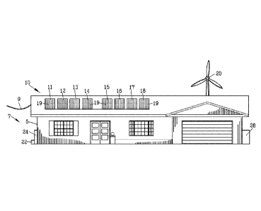
FIG. 1 is a front view of a building structure 5 incorporating an interface
for renewable
energy system 7 for interconnectinil. a plurality of power sources to an AC
power grid 9. The
plurality of power sources include a photovoltaic solar array 1.0 and a wind
turbine 20. .Preferably,
the photovoltaic solar array 10 and the wind turbine 20 incomorate an energy
storage unit such as
a battery array 22 and/or a fuel cell array 24. Preferably a fuel operated
generator 26 is
incorporated into the system .for emergency operation.
The photovoltaic solar array 10 is illustrated having a plurality of -
photovoltaic solar panels
1.1-18, Although the building structure .5 has been shown as a residential
building structure, it
should be understood that the photovoltaic solar array 10 may be mounted on -
Virtually any type of
building structure as well as being mounted on a ground surface.
Each of the plurality of photovoltaic solar panels 1148 is made from a
multiplicity of
photovoltaic solar cells 19. Typically, each of the photovoltaic solar cells
19 generates
approximately 0.5 volts. The photovohaic solar cells 19 are connected in
series¨parallel to
provide approximately 300 watts of power at 30 v(111S,
In some instances, individual photovoltaic solar panels 1.1-18 are mounted on
equatorial
mounts (not shown) for following the movement: of the sun throughout the day.
The structure and
operation of an equatorial mount is notoriously well known to those skilled in
the artõ
FIGS. 2-4 are rear view of the photovoltaic solar panels 11-14 of FIG. I. Each
of the
photovoltaic solar panels 11-14 includes a junction box 11J-145 for connecting
the MUltiplicity of
solar cells 19 to positive conductor 1.1+ to 14 + and negative conductor 11-
to 14 ¨. The
photovoltaic solar panel 13 defines a peripheral frame 30 including opposed
peripheral frame rails
31 and 32 and opposed peripheral frame rails 33 and 34..
A container 40 extends between a first and a second end 41 and 42. The
container 40
includes mounting arms. 43 and 44 shown as flanges 45 and 46 extending from
opposed ends 41
.30 and 42 of the container 40. The flanges 45 and 46 of container 40 are
secured to the opposed
peripheral frame rails 31 and 32 of the 'photovoltaic solar panel 13. The
flanges 45 and 46 make
thermal contact with the peripheral frame rails 31 and 32 of the photovoltaic
solar panel 13 -for
transferrim2, heat from the container 40 -to the peripheral frame 30 of the
solar panel 13.
CA 02906590 2015-09-14
WO 2014/152765 PCT/US2014/027708
A. closure 50 engages with the container 40 to form a weather tight seal with
the container
40 for housing a multi-channel micro-inverter 60 within the container 40.
Preferably, the closure
30 is secured to the container by a plurality of threaded fasteners 55 for
permitting removal of the
closure 50 tor servicing or re placing the multi-channel micro-inverter 60
'therein.
As best shown in FIG. 4, the multi-channel micro-inverter 60 comprises a
plurality of
independent micro-inverter boards 61-64. As will be described in greater
detail hereinafter, each
of the micro-invener board 61-64 is independently mounted in the: container 40
for replacement
and repair. The micro-inverter boards 61-64 are secured to the container 40 by
a plurality of
.threaded fasteners 66 enabling a micro-inverter board to be inserted and
removed for repair or
replacement.
Preferably, four independent micro-thVerter boards 61-64 are mounted in the
container 40
enabling 30 ampere wire to be used to connect the multi-channel micro-inveder
60 to an. external
load or to an external electrical grid.
Each of the micro-inverter boards 61-64 has a micro-inverter DC power input
611-641 and
1 5 an AC
power output 610-640. The positive conductor 11+ to 1.4 + and negative
conductor 11- to
1.4
of .the photovoltaic solar panels 11-14 are connected to the power input 611-
641 of the
plurality of independent micro-inverter boards 61-64.
A plurality of micro-inverters '71-74 are disposed on the micro-inverter
boards 61-64. The
micro-inverters 71-74 receive DC power from the power inputs 611-641 of the
plurality of
independent micro-inverter boards 61-64 and provide AC Power on the AC power
output 610-
640 of the plurality of independent micro-inverter boards 61-64. A plurality
of regulators 81-84
are disposed on the micro-inverter boards 61-64 for controlling the micro-
inverters 71-74 and for
providing communication between the micro-inverter boards 61-64.
An AC power bus interconnects the AC power output 610-640 of the plurality of
independent micro-inverter boards 61-64 in a parallel configuration. The
combined AC power
output 610-640 of the plurality of independent micro-inverter boards 61-64 is
provided on a
multi-channel. micro-inverter power output conductor 130. In this embodiment,
the AC power
bus is shown as AC cables 71AC-73AC connecting the AC power output 610-630 of
the plurality
of independent micro-inverter boards 61-63 to the AC power output 640 of the
micro-inverter
.30 board
64. An AC cable 74AC connects the AC power output 640 of micro-inverter board
64 to
the multi-channel micro-inverter power output conductor 130.
A data bus interconnects the plurality of regulators 81-84 disposed on the
micro-inverter
boards 61-64 tbr providing digital communication between the micro-inverter
boards 61-64. In
12
CA 02906590 2015-09-14
WO 2014/152765 PCT/US2014/027708
this embodiment, the data bus is shown as jumper cables 81D-83:D connecting,
the plurality of
regulators 81-84.
A controller 90 is located on one of the micro-inverter board 64. The
controller
communicates with the plurality of regulators 81-84 for monitoring and setting
.the parameters of
the operation of the independent micro-inverters. 71-74. Preferably, the
controller 90
communicates with the plurality of regulators 81-84 through an inter micro-
inverter network
protocol such as RS-485 data link or an optical link. in addition, the
controller COMMUIlicates with
the plurality of regulators 81-84 for monitoring the operation of the
photovoltaic solar panels 11-
14 and for .monitoring the operation of the micro-inverters 71-74.
Furthermore, the controller 90
communicates the monitored data through multi-Channel micro-inverter power
output conductor
130 for transfer to a remote location by power line carrier communications
(PLCC). The
controller 90 modulates the AC power with the monitored data on the AC power
output 640 of
micro-inverter board 64. The monitored data, on the AC power exits the multi-
channel micro-
inverter power output conductor 130 :for transfer to a remote location. The
more detailed
explanation of the operation of the plurality of regulators 81-84 and the
controller 90 will be set
forth hereafter,
HO. 5 is an enlarged sectional view along line 5-5 in FIG, 4. Each of the
micro-inverters
71-74 has a power stage comprising micro-inverter switches 71S-74S and micro-
inverter
transformers 71T-74T. A non-electrically conductive thermal conductive medium
95 thermally
coupled the power stage of the micro-inverter '71-74 to one of .the container
40 and the closure 50.
The container 40 transfers heat from the power stage of the micro-inverter 71-
74 to the peripheral
frame 30 of the solar panel 13. Preferably, the thermal conductive medium 95
comprises a first
.thermal transfer medium 96 interposed between the power stage and the
container 40 and a second
'thermal transfer medium 97 interposed between the power stage and the closure
50 for thermally
coupling the power stage to the container 40.
The micro-inverter hoard 61 defines an under side and an upper side of the
micro-inverter
board 61, In -this embodiment, the micro-inverter switches 7.1S-74S are
mounted on the underside
of the micro-inverter boards 6144 whereas the micro-inverter transformers 71T-
74T are mounted
on the upper side of the micro-inverter boards 61-64. In the example, the
.micro-sinverter switches
.30 71S-74S are shown as metal oxide semiconductor field effect transistors
(1140SFET) with the
metal component them& mounted remote from the micro-inverter circuit board.
61. A first
resilient thermal transfer medium 96 is interposed between the metal component
of the micro-
inverter switches 71S-74S and the container 40 A second resilient thermal
transfer medium 97 is
13
CA 02906590 2015-09-14
WO 2014/152765 PCT/US2014/027708
interposed between the micro-inverter transformers 71T-74T and the closure 50.
The first and.
second thermal nansfer mediums 96 and 97 thermally couple the power stage to
the peripheral
frame 30 of the solar panel 13. The thermal transfer from .the micro-inverters
to the container 40
coupled with the thermal transfer from the container 40 to the .pertpheral
frame 30 of the solar
panel .13 eliminates the need for heat sinks and cooling fans for the multi-
channel micro-inverter
60.
It has been found that the use of four micro-inverters 61-64 in a. single
container 40 is the
optimum for heat dissipation and weight when the four micro-inverters 61-64
are void of any heat
sinks or cooling fans. The elimination of heat sinks and cooling fans
increases the overall
efficiency and lowers the cost of the four micro-inverters 61-64 in a single
container 40. In
addition, the use of four micro-inverters 61-64 in a single container 40
pennits 30 ampere vvire to
be used for the AC power output of the multi -channel micro-inverter 60.
FIGS. 6-1.0 illustrate a second embodiment of a container 40A for the multi-
channel
micro-inverter 60 of the present invention In this embodiment, the container
40A extends
is between a First and a second end 41.A and 42A. 'The container 40A
includes through apertures
43A. A shield 44A is secured to form a seal with the bacl . of the container
40A. Flanges 45A and
46A extend from opposed ends 41A and 42.A of the container 40A for securing to
the opposed
peripheral. .frame rails 31 and 32 of the photovoltaic solar panel 13 as shown
in FIGS. 2-1 The
flanges 45A and 46A make thermal contact with the .peripheral frame rails 31
and 32 of the
photovoltaic solar panel 13 for transferring heat from the .container 4,0A to
the peripheral frame 30
of the solar panel 13. 'The container 40A defines a plurd14 of slots 48A the
function of which will
be described in greater detail here and after.
A plurality of closures 51A-54A includes tabs 51T-54T extending from the
closures 51A-
54A. The tabs 51T-54T of the plurality of closures 51A-54A cooperate with the
plurality of slots
48A. to secure the plurality of closures 51A-54A to the container 40A.
Each of the micro-inverter boards 61-64 independently engages a thermal
conductive
medium or may be encapsulated M a non electrically conductive and .thennal
transfer potting
compound 95A The micro-inverter boards 61-64 are independently housed in the
plurality of
closures 51A-54A.
.30 FIG. I is an enlarged side sectional view of the first step of
inserting the micro-inverter
board 64 into the container 40A of FIGS. 6-10. The micro-inverter board 64 is
placed within the
closure 54A. The AC cables 71AC-7.3AC shown in FIG. 4 are connectal from the
AC power
output 610-630 of the plurality of independent micro-inverter boards 61-63
through the apertures
14
CA 02906590 2015-09-14
WO 2014/152765 PCT/US2014/027708
43A, to the AC povver output 640 of the micro-inverter board 64. Similarly,
.the jumper cables
81D-83D shown in FIG, 4 extend through the apertures 43A to connect the
.pluralny of regulators
81-84. An AC cable 74AC connects :the AC power output 640 of micro-inverter
board 64 to the
micro-itiverter power output conductor 130.
FIG. 12 is an enlarged side sectional \dew of the second step of inserting a
micro-inverter
board 64 into the container of FIGS. 6-10. The tab 54T extending from the
closure 54A. is inserted
into the slots 48A,
FIG. 13 is an enlarged side sectional view of the .final step of inserting a
micro-inverter
board 64 into the container of FIGS, 6-10. The closure 54A .is rotated about
the tab 54T enabling
.the Closure 54A to be secured to the container 40A by a plurality of threaded
fiisteners 55A,
When the closure 54A is fastened to the container 40A by the plurality of
threaded fasteners 55A,
the closure 54A applies pressure to thermally engage the power stage of the
micro-inverter 74
including the micm-inverter switch 74S and the .inicro-inverter transformer
74T to the container
40A.
FIG, 14 is a rear view of photovoltaic solar panel. 13 of .171G. I. with a
second embodiment
of a mounting the container 40B of the mutti-channel micro-inverter 60 to the
photovoltaic solar
panel 13. The container 4013 extends between a first and a second end 41B and
42Bõ The
container 4013 includes mounting arms 4313468 extending from opposed ends 41B
and 42.13 of the
container 4013. The mounting arms 4313-4613 secure the container 40B to the
opposed peripheral
frame rai.ls 3.1 and 32. of .the photovoltaic solar panel 13. The mounting
arms 43B46B make
thermal contact with the peripheral frame rails 31 and 32 of the photovoltaic
solar panel 13 for
transferring heat from the container 40B to the peripheral frame 30 of the
solar panel 13.
The micro-inverters 6113-64B are approximately ninety five percent (95%)
efficient
Assuming an output of 250 Watt per micro-inverter 61.B4A13, the total heat to
be .dissipated by the
enclosure is approximately 50 watts. 'TO reduce cost, the power output stages
of the micro-
inverters 61B-64B are void of heal sinks and coolinn fans. In this embodiment,
the power output
stages of the micro-inverter 61B-64.13 are distributed about remote portions
of the container 4013
for distributing the heat of the power output stages. Mounting the containc,,r
40B in the geometric
center of the solar panel frame 30 provides better heat distribution for the
power outputs and for
.30 the photovoltaic solar panel 13.
The container 4013 is mounted in the geometric center of the peripheral frame
30 to insure
the center of mass of the container 408 coincident with the center of mass of
the photovoltaic solar
panel 13. The coincidence of the center of mass of the container 40B and the
photovoltaic solar
CA 02906590 2015-09-14
WO 2014/152765 PCT/US2014/027708
panel 13 provides a superior weight distribution in the event the photovoltaic
solar panel. 13 is
mounted. on an equatorial mount (not shown).
HQ. 15 is an enlarged sectional view of a portion of FIG. .14 illustrating the
connection of
the .mounting arm 4613 to the container 4013 enabling the mounting arm 4313 to
pivot relative to the
container 4013,
HQ. 16 is an enlarged sectional view of a portion of FIG. .14 illustrating
.the connection of
the mounting arm 4613 to the peripheral fillMe rail 32 of the solar panel 13.
The mounting arm
4613 is connected to a. bracket 5713 by a threaded film:crier 5613. The
bracket 5713 is connected to
.the peripheral frame rail 32 of the solar panel 13 by mechanical fasteners
shown as self taping
0 screws 5813
FIG. .17 illustrates an alternate connection of the mounting arm 4313 to the
container 4013.
The mounting arm 4313 includes a first mounting arm section 43C and a second
mounting arm
section 431). A longitudinally extending, slot 5913 is defined in the second
mounting arm section
43D of the mounting arm 4313. A mechanical fastener 59C engages with the slot
5913 to adjust the
is length of mounting arm section 431) relative to the mounting arm section
43C thereby adjusting
.the length of the mounting ann 4311 to the solar panel 13. The mourning
system Shown in FIGS.
14-17 enables the container 4013 to be mounted to different sizes of solar
panels 13.
FIG. 18 is a. diagram of the renewable energy system 7 is capable of operation
in three
modes namely a grid tied operation mode, an off grid operation mode and an
emergency operation
20 mode. The interthce thr renewable energy system 7 switches automatically
between the grid tied
operation mode, the off grid operation mode and the emergency operation mode.
The renewable energy system 7 comprises multiple photovoltaic arrays 10A and
1013.
Each of the multiple photovoltaic solar arrays 10A and 1013 is identical to
the photovoltaic solar
arrays .10 shown in FIGS, 2-5. Each of the multiple photovoltaic solar arrays
1.0A and 108
25 includes a multi-channel micro-inverter 60. The multi-channel micro-
inverter 60 of the
photovoltaic solar arrays 10A and 1013 are connected by electrical cables 101
and 102 to a junction
box .103. As previously described, the preferred configuration of four micro-
inverters per multi-
channel micro-inverter enables 30 ampere cable to be used for eltxtrical
cables 101 and 102. The
output of junction box .103 is connected by cable 104 to a junction box 105.
.30 The renewable energy system 7 comprises the wind turbine 20 connected
to a micro-
inverter 60. The micro-inverter 60 of the wind turbine 2.0 is connected by
electrical cable 106 to
the junction box .105.
The interface for renewable energy system 7 includes a switching matrix 110
comprising
16
CA 02906590 2015-09-14
WO 2014/152765 PCT/US2014/027708
switches 111-114. The switches 111-1.14 are connected to conductors 115-118.
The junction box
105 is connected by conductor 115 to the switch 111 of the switching matrix
110,
The fuel operated generator 26 is connected by the conductor 116 to the switch
11.2 of the
switching matrix 110. The ftiel operated generator 26 may be any type of
generator operating on a
petroleum based fuel such as diesel, gasoline, natural gas, propane and the
like. The fuel operated
generator 26 operates only in emergency situation and only upon the loss of AC
power from the
AC power grid 9.
The AC power grid 9 is shown as a conventional external electrical grid .120
of 120 volt at
60 Hz. It should be appreciated that the interface for renewable energy system
7 is suitable for use
with 120 to 240 volt 50-60 Hz electrical systems. The external electrical grid
1.20 is connected
through a conventional wattmeter 122 and conductor 117 to the switch .113 of
the switching matrix
110. Since the fuel operated generator 26 operates only in emergency situation
and only upon the
loss of AC power from the AC power grid 9, switch 11.2 and 1,13 may be
mechanically
interconnected to prevent the simultaneous closing of switches 112 and 113.
The battery array 22 is connected to a multi-channel micro-inverter 60W. The
output of
.the multi-channel micro-inverter 60W is connected through conductor 1.18 to
the .switch 114 of the
switching matrix 110. The multi-channel micro-inverter 60W operates in two
modes, in the first
mode of operation, the multi-channel micro-myerter 60W to convert DC power
from the battery
array 22 into AC power as previously described, in the second mode of
operation, the multi-
channel micro-inverter 60W operates as battery charger for charging battery
array 22 upon AC
power appearing on conductor 118.
Preferably, the multi-channel micro-inverter 60W includes a waveform generator
125.
When actuated, waveform generator 125 produces a 60 .1-1z sine wave for
synchronizing the Phase
of .the .AC power produced by the micro-inverters 60 in the absence of a AC
power from the
external electrical grid 120. The operation and function of the waveform
generator 125 will be
discussed in greater detail hereinafter.
The fuel cell 24 is connected to a multi-channel micro-inverter 60. The multi-
channel
micro-inverter 60 is connected through conductor 118 to the switch 114 of the
switching matrix
110.
.30 An
electrical service circuit breaker box 140 is connected by conductor 1.19 to
the
switching matrix 110, The electrical service circuit breaker box 140 powers a
load 145
represented by conventional electrical outlets 146. The opening and closing of
switches 11.1-114
connect the various power sources connected to the conductors 115-118 to the
electrical service
17
CA 02906590 2015-09-14
WO 2014/152765 PCT/US2014/027708
circuit breaker box 140 to power the load 145.
Sensors 150 represented by the sensor box a.re connected to receive input 151 -
from the
interface for renewable mew qstern 7, The sensors 150 monitor the -various
parameters of the
various -power sources. connected to the conductors 115-118. An output 152 of
the sensors 150 is
connected to a master control 160 for opening and. closing the switches 111-1-
14 as will be
described hereinafter.
An electrical monitor controller 170 is connected to the interface for
renewable energ
system 7 for remotely monitoring the operation of the interface for renewable
mew, system 7 and
fbr -receiving instruction from a remote location. The electrical monitor
.controller 170 is
connected to the interfa.ce for renewable energy system 7 by a data conductor
172. The electrical
monitor controller (EMC) 170 communicates with the controllers 90 of the multi-
channel micro-
inverters 60 and the master control 160 by power line carrier communications
.(PLCC). In
addition, the electrical monitor controller (EMC) 170 provides communication
with the interact
180 for remotely monitoring, remotely alerting, or remotely entering
instruction from a computer
182 or a mobile device 184 into the controllers 90 of the multi-channel micro-
inyerters 60 and the
master control 1.60.
FIG. 19 is a logic diagram of the operation of the interface for renewable
.energy system 7
of -FIG. I 8. The logic diagram illustrates the program stored. -in the master
control 160 of FIG IS.
The logic diagram ilkistrates -various alternative operations available to the
interface .for renewable
energy system 7 when operating in a grid tied mode of operation.
Furthermore, the logic diagram illustrates various alternative operations
available to the
interface for renewable energy system 7 upon loss of AC power on the
electrical grid 120, The
logic diagram illustrates the ability of the interface -ibr renewable .energy
system 7 to switch
automatically between the grid tied mode of operation and the off grid mode of
operation. The
operation of the interface tbr renewable energy system 7 in accordance with
the program stored in
the controller 160 is further illustrated with reference to -FIGS. 20-23.
The interface for renewable energy system 7 automatically operates in three
modes. FIGS.
20 and 2.1 illustrate the interface ibr renewable energy system 7 in a. grid
tied operafion mode.
FIG. 23 illustrates the interface for renewable energy system 7 in an off grid
operation mode. FIG.
.30 24 illustrates the interface fbr renewable energy system 7 in an
emergency operation mode.
FIG. 20 illustrates a first example of the circuit diagram of the interface
for renewable
energy system 7 of FIG 18. Voltage sensors Vi -V5 sense the voltage at the
switches 1.11-1.14 and
the load 145. Similarly, current sensors 11-15 sense the current at the
switches 111-114 and the
18
CA 02906590 2015-09-14
WO 2014/152765 PCT/US2014/027708
load .145. The controller 160 receives the input from sensors Vi -V5 and .1145
and. provides output
to switches 111414 in accordance with the program stored in the controller
160.
FIG. 20 illustrates the circuit diagram of .the interface for renewable
ertertiy syste.m 7 in a
first electrical grid-tied operating mode wherein AC power is present on the
electrical grid 120.
The switch 1.13 is closed -for connecting the external electrical grid.. 120
to the interface for
renewable energy system, 7. The switch 112 is open for disconnecting the fuel
operated generator
26 from the external electrical grid 120. An interlock within the .controller
160 prevents the
simultaneous closing of switches 112 and 1.13. Furthermore, switches 1.12 and
1.13 may be
mechanically interconnected to prevent the simultaneous closing of switches
112 and 1.13,
0 Switch
1.11 is closed enabling the photovoltaic solar panel arrays 1.0A and .10B
and/or the
wind turbine 20 to provide renewable AC power to the external electrical grid
120 through closed
switch 113. The renewable AC power generated by the mithi-channel .micto-
inverters 60 is
maintained in phase with the external electrical grid 120 by the regulators 81
and the controllers
90 within the .multi-channel micro-inverter 60: The controllers 90 within the
multi-channel micro-
inverters 60 monitor the phase of the external electrical grid 120 and control
the micro-inverters 60
accordingly.
Switch 114 is closed enabling the photovoltaic solar panel arrays 10A and
'1013 and/or the
external electrical gTid .1.20 to charge the battery array 22, The multi-
channel micro-inverter 60W
operates as a battery Charger for charging the battety array 22. The waveform
generator 125 is
inactive since the external electrical grid 120 provides a sine wave that is
followed in phase by all
of the multi-channel micro-inverters 60. The multi-channel micro-inverter 60W
operates to
recharge the rechargeable fuel cell 24.
FIG. 21 is a circuit diagram similar to FIG. 20 with the interface for
renewable energy
system 7 in a second electrical .grid-tied operating mode,. In the event the
battery array 22 andlor
the fuel cell 24 has obtained maximum charge capacity as indicated by the
voltage on V4, the
controller 160 opens switch 114 to prevent fudtet charging of the battery
array 22 andlor the fuel
cell 24.
FIG-. 22 i.s a circuit diagram similar to PIG. 20 with the interface for
renewable enemy
system 7 in an off-grid operating mode. Upon the 'Joss of. AC power from. the
.extemal electrical
.30 grid
120, the sensor V3 senses the loss of voltaRe and the controller 160 ORM; the
switch 113 to
disconnect the external electrical grid 120 from the interface for renewable
energy system 7.
Preferably, a time delay is incorporated into the controller 160 for
.providing a timed duration prior
to opening 113 for accommodating for transient voltage fluctuations.
19
CA 02906590 2015-09-14
WO 2014/152765 PCT/US2014/027708
Optionally, the master control 1.60 may open the switch 113 to disconnect the
external
electrical grid 120 from the interface for renewable energy system 7 in the
event elan over voltage
on the external electrical grid 120 thereby protecting the interface .for
renewable energy system. 7
from damage due to an over voltage condition.
Upon opening the switch 11..3, the controller 160 closes switch .114 and
activates the
waveform generator 125. The multi-Channel micro-inverters 60W converts the DC
power .l.rom
the battery array 22 into AC power following the phase of the waveform
generator 125, The AC
power from the multi-channel micro-inverters 60W is directed to the load 145..
Switch il I is closed enabling the photovoltaic solar panel arrays 1.0A and
.1013 and/or the
wind turbine 20 to provide renewable AC power to the toad 145. The renewable
AC power
generated by the multi-channel micro-inverters 60 is maintained M phase with
the waveform
generator 125.
In the event the photovoltaic solar panel arrays 1.0A and 1.013 and/or the
wind turbine 2.0
provide more electrical power than required by the load 145, then the
controller 160 enables the
is multi-
channel micro-inverter 60W to charge the battery array 22 and/or the
rechargeable fuel. cell
24. In .the event the battery array 22. and/or the fuel cell 24 has obtained
maximum charge capacity
as indicated by the voltage on V4, the controller 160 opens switch 114 to
prevent further charging
of the battery array 22 and/or the fuel cell 24. in the alternative. the
controller .160 may open
switch III to disconnect the photovoltaic solar panel anws 10A and 108 and/or
the wind turbine
20 and close switch 11.4 to dissipate excessive charge in .the battery array
22 and/or the fuel cell 2.4
to the load 145.
The photovoltaic solar panel arrays 10A and 1013 and/or the wind turbine 20
work in
concert with the bane*, array 22 and/or the rechargeable fuel cell 24 for
providing reliable AC
power to the load, In the event photovoltaic solar panel arrays 10A. and. .10B
and/or the wind
turbine 20 provide less electrical power required by .the load 145 due to
clouds, nightfall or the
absence of wind, the battery array 22 and/or the rechargeable fuel cell 24
provides supplemental
AC power .to the load. The switch 112 remains open keeping the fuel operated
generator 26
disconnected from the interface for renewable energy system 7 until the
depletion of the stored DC
power in the battery array 22.
.30 FIG.
23 is a circuit diagram similar to FIG. 20 with the interface for renewable
energy
system 7 in. an emergency operating mode. An emergency condition exists when
the()) the loss
of AC power from the external electrical grid 1:20, (2) the inability of the
photovoltaic solar panel
arrays 10A and 1013 and/or the wind turbine 20 to provide sufficient AC power
to the load 145 and
CA 02906590 2015-09-14
WO 2014/152765 PCT/US2014/027708
(3) the depletion of DC power stored in the battery array 22. and/or the
rechargeable fuel cell 24
simultaneously exists.
In the emergency operational mode, the controller 160 -terminates operation of
the
waveform generator .125. The controller .160 closes switch 112 and actuates
the fuel operated
generator 26. The fuel operated generator 26 provides emergency power to the
load 145 as well as
AC power tocharge the battery array 22 and/or the rechargeable fuel cell 24.
In the event, the DC power from the photovoltaic solar panel arrays 10A and
1013 and/or
the wind turbine 20 is restored, the controller 1.60 terminates operation of
the fuel operated
generator 26, opens switch 11.2 and activates the waveform generator 125 to
return to the off-arid
operating mode as heretofore described.
When the AC -power from the external electrical grid 120 is restored, the
controller .160
returns the switches 111-114 to the positions shown in FIG. 20 with the
waveform generator 125
in a deactivated condition. It should. be appreciated that the interface for
renewable .energy system
7 switches automatically between the grid tied operation mode, an off grid
operation mode and the
emergency operatioi mode while still meeting electrical safety standards ..
FIG. 24 illustrates a second example of the circuit diagram of the renewable
energy system
7 of HO. 18. In this example, the controller 16013 is a hard wired electrical
.circuit void of
programmable electronic components. The voltage sensor V3 senses the voltage
from the external
electrical grid 120. The output of the voltage sensor V3 is applied to a
window comparator 200
having comparators 201 and 202. The output of the window comparator 200 is
connected to the
switch 11.3 through delay circuit 205. The delay circuit 205 eliminates
transient: voltages on the
external electrical grid 120 from changing the switch 113.
A proper voltage of the external electrical and 120 produces a high output
from the
window comparator 200 to close switch 113. An over voltage or an under voltage
of the external
electrical grid 120 produces a zero output from the window comparator 200 to
open switch
The voltage sensor V3 is also connected through art inverter 208 to an AND
gate 210. The
output of AND gate 210 is connected to control switch 112. A. proper voltage
of the external
electrical grid 1.20 produces a low output from the AND gate 210 to open
switch 112.
A comparator 215 compares a reference DC voltage 216 with the voltage of the
battery
.30 array 22. The output of the comparator 215 is applied through an
inverter 217 to the AND gate
210, The AND gate 210 closes switch 112 only upon (I) the loss of voltage of
the external
electrical grid 1.20 and (2) the voltage of the battery array 22 is below the
reference voltage 21.6.
The output of the comparator 215 is applied through an -inverter 217 to an OR
gate 220.
21
CA 02906590 2015-09-14
WO 2014/152765 PCT/US2014/027708
The OR gate 220 receives an input from the voltage sensor VI The output of OR
gate 220 is
connected to control switch 111. The OR .gate 220 closes switch I I when (1) a
proper voltage
appears on the external electrical grid 120 or (2) the voltage of the battery
array 22 is below the
reference voltage 216.
The output of the comparator 215 is applied through the inverter 217 and
inverter 225 to
control switch 1 .14. The comparator 21.5 closes switch 114 when the voltage
of the battery array
22 is below the reference voltage 216.
An example of switching circuit suitable for fuel operated generator switch.
112 and the
external electrical grid switch 113 is disclosed in US Patent 8,134,820 which
is incorporated by
reference as if fully set forth herein.
FIGS. 25 and 26 are a block diagram and a simplified circuit diagram of a
micro-inverter
71 suitable for use with the present invention. The micro-inverter 71
described is a grid-connected
solar micro-inverter reference design using a dsPIC digital signal controller
(AN133S).
The micro-inverter 71 comprises a DC to DC converter 71.0 comprising Plural
switches
is 71S and plural transformers 71T. The DC power input from the solar array
10 is applied to
primary windings of each of the plural transformer 71T. The plural switches
7.1S are connected in
series with the plural transformer 71T, respectively. The plural switches 71S
are controlled by the
regulator 81. Each of the plural switches 71S -produces a pulsating DX1 .
waveform in the shape of a
positive half cycle of an AC waveform, The regulator Si controls the -plural
switches 71.5 to
produce pulsating DC waveforms having an elevated voltage and one hundred and
eighty degrees
out of phase with one another. Each of the pulsating DC waveforms is elevated
in voltage. The
regulator 81 controls the plural switches 71 S to produce maximum power output
from the voltage-
current output curve of the solar array 10. A complete technical discussion
.of the dsP1C digital
signal. controller (AN1338) manufactured by Microchip Technology Inc. may be
found in
technical bulletin for the &PIC digital signal controller (AN1.338) which is
hereby incorporated by
reference as if fully ser forth herein.
The regulator 81 is able to throttle back the output of the micro-inverter 71
by the electrical
monitor controller (EMC) .170 communicating through the internet 180 for
remotely entering
instruction into the controllers 90 of the multi-channel micro-inverters 60.
In some instances, too
.30 much renewable energy power is introduced into the external. electrical
grid 120. The electrical
monitor controller (EMC) 1.70 enables an external source such as an
.electrical power company -to
throttle back the regulators 81 to reduce the amount of the renewable energy
power introduced
into the external electrical grid 120.
22
CA 02906590 2015-09-14
WO 2014/152765 PCT/US2014/027708
HG. 27 is a block diagram illustrating a redundant power supply 65P for the
controller 90
of the multi-channel micro-inverter 60. Each of the inverters 81-84 includes a
power supply 61P-
64P. Each of the power supplies 61P-64P is connected to a diode O.R gate 85 to
provide power to
the controller 90. In the event one or more of the power supplies 61P-64P
and/or solar panels II-
14 should fad, the remaining power supplies 61P-64P will still provide power
to the controller 90.
FIG. 28 is a block diagram illustrating a controller 90 communicates with the
plurality of
micro-inverters circuits 61-64. The controller 90 communicated with each of
the regulators 81-84
through the data cables 81D-84D. The data cables 81D-84D may be a PnP. RE-485
or infrared
(IR) communication systems. The controller 90 monitors and provides
instructions to each of the
micro-inverters circuits 61-64. H.owever, each of the micro-inverters circuits
61-64 operates
independently of the remaining micro-inverters circuits 61-64.
FIG. 29 is a block diagram illustrating the electrical monitor controller
(EMC) 170 for
communication with the controller 90 of the plurality of multi-channel micro-
inverters circuits 60.
Lines labeled "L" (Line) and "N" (neutral) are use as media to carry analog
data to and from the
s micro-inverters 6.1-64 installed at or near the solar collectors 11-14.
The digital signal controller (dsP1C33) is an Analog-to-Digital Converter,
converting
either a Utility Band operating at 6Kbps (kilobits per second), 721(hz
(kilohertz) utilizing Forward
Error Correction (EEC) or a Consumer Band operating at 7.2 Kbps, 129.6Khz with
no Forward
Error Correction. The digital signal controller is also referred to as a
Peripheral Interface
Controller or a Programmable Intelligent Computer.
The micro inverters 60 installed at or near the solar collectors send data
such as current
output, watt output in an analoe form which is first received by the PLCC
Analog Front End, The
PLCC receives the signal that has been transmitted though the power lines to
create an analog
signal that the dsPIC33 can further process. The dsPIC33 sends analog data to
and from the micro
inverters 60. Once the dsPIC33 has received some analog data. from the micro
inverters 60, the
dsPIC33 then: can send and receive digital data to and from the PIC24 via. PC,
The PC is an Inter-
Integrated Circuit bus connecting the dsPIC33 to the PIC24. The PIC24 is a
microcontroller where
instructions are stored in the non-volatile memory called Program Memaly the
data from the
dsPIC33 is stored in the P1C24's Data Memory. The instructions (programs)
stored and executed
.30 by the PIC24 include HTTP (Hypertext Transfer Protocol), FTP (file
Transfer Protocol), SMTP
(Simple Mail Transfer Protocol), IP (Internet Protocol), TCP (Transmission
Control Protocol),
DHCP (Dynamic Host Configuration Protocol), ARP (Address Resolution protocol),
ICMP
(Internet Control Message Protocol), and UDP (User Datagram Protocol), The H
__ 11P (web
23
CA 02906590 2015-09-14
WO 2014/152765 PCT/US2014/027708
server) instructions stored in ,the P1C24's Program Memory gives technicians
or homeownen3 the
ability to input and see real time information, such as, power outputs,
temperature, and status of
.the system, using a standard web browser. The SMTP server gives the unit the
ability to send
mails to a technician or homeowner when specified events have or will
occurred, such as a failure
in one of the system components (solar panel, micro inverter, grid power loss,
grid power low, grid
power restored, etc). The PIC24 is programmed to handle TCP/1P stack which
allows for the
remote communication using a Network Interfac.e Controller (ENC28.160 in
diagram), The
Network Interface Controller converts instructions to be trans.mi tied over a.
physical transmission
media, such as cabling (electric voltages), wireless (radio frequencies)
and/or infrared (pulses of
infrared or ordinary light) to be, delivered to ultimately another Ethernet
controller. The remote
computer with an installed Ethernet controller can then view the programs
running on the PIC24,
such as H I IP to remotely view real time data including current Volts,
Current output, Status of
the system, Temperature of the system. Watts and Kilowatt HOW'S being
produced. The P1C24
also includes a direct input and output to and LCD/MM! Message Center Display
FIG, 30 is a diagram of similar to Ha 18 illustrating an apparatus 250 for
mapping and
identifying a. perfomiance and/or .fault in a solar panel of a. solar panel
array. The solar arrays have
a multiplicity of solar panel groups with each solar panel groups having a
plurality of solar panels
mounted in a specific physical pattern. In this example, three solar panel
arrays 10E-1,00 arranged
in alphabetical order. The first solar panel arrays 10E comprise four groups
of solar panels. The
first group includes solar panels P 1.11-P114, the second group includes solar
panels P121-P124,
the third group includes solar panels PI31-P134 and the fourth group includes
solar panels P141-
P144.
In a. similar manner, the second solar panel arrays .10F comprise four groups
of solar
panels including solar panels P211-P214, the second group includes solar
panels P221.-P224, the
third group includes solar panels P231 -P234 and .the fourth group includes
solar panels P241-
P244,
The .third solar panel arrays 100 comprise four groups of solar panels
including solar
panels P311.-P314, the second group includes solar panels P321-P324, the -
third group includes
solar panels P33I -P334 and the fourth group includes solar panels .P341-
P344.,
.30 Each
of the groups of solar groups of solar panels includes a micro-inv-erter 60.
The
micro-inverters are secured to a single and identifiable solar panel of each
of the solar panel
groups. in this example, the micro-inverters 60 are secured to the first solar
panel each of the
groups of each of the solar arrays 10E- I 00
24
CA 02906590 2015-09-14
WO 2014/152765 PCT/US2014/027708
Micro-inverters 60 are secured to the first solar panel P.1.11., P1.21, P131
and P141 of the
solar panel array 10E. Micro-inverters 60 are secured to the first solar panel
P211, P221, P231
and P241 of the solar panel array 10E Micro-inverters 60 are secured to the
first solar panel P311,
P321,, P331 and P34.1 of the solar panel array 10G.
FIG 31 is a. block diagram similar to FIG 27 illustrating the micro-inverter
60. Each of
.the micro-inverters 60 has a unique identification numeral for the micro-
inverter 60 and with each
of the micro-inverters 60 having, numbered inverter ports. In this example,
each of the micro-
inverters 60 has four numbered inverter ports 611-641 for connection to four
solar panels in the
solar panel group,
0 The
micro-inverter 60 includes the client controller 90 that communicates with the
plurality of regulators 81-84 for monitoring and setting the parameters of the
operation of the
independent micro-inverters 71-74. In addition, the controller 90 communicates
with the Plurality
of regulators 81-84 for monitoring the operation of the photovoltaic solar
panels connected to the
inverter pods 611-641.
is
Referring back to FIG. 30, a plurality of cables connect the solar panels to
specific
numbered inverter .ports of the micro-inverter 60 .lbr correlating the
numbered .inverter ports to
specific physical locations of the plurality of solar panels within each of
the solar panel groups.
Preferably, .the solar panels of a group are mounted in a pre-established
specific physical
pattern 'based on a length of the cables connecting the solar panels to the
numbered inverter ports
20 of
the micro-inverter 60. In this example, the micro-inverters 60 secure to solar
panel Pill has
numbered inverter ports 611-641 (1, 2, 3 and 4) connected to solar panels
(P111, P112, P113 and
PI14), respectively, Thus, the cables connected to numbered inverter port 611-
641 (1-4) range
from the shortest to the longest cable with numbered inverter port 611 (1)
being the shortest and
numbered inverter port 641 (4) being the longest. 'The remaining inverters 60
secure to solar panel
25 PI
1.1-P344 of the solar arrays 1.0E-1.0G and are connected in as similar manner
as shown in FIG.
30,
A first trunk line 130E connects the micro-inverters 60 of .the first solar
array 10E .to a first
circuit breaker 261. Similarly, a second and a third trunk line 130F and 130G
connect the micro-
inverters of the second and third solar arrays 1017 and 10G to a second and a
third circuit breaker
.30 262
and 263. A fourth trunk line 130H is shown for connection to a micro-inverter
of another
renewable energy source such as the windmill 20 shown on FIG. 18. The first
through fourth
breakers 261-264 are connected to the EMC I 70A shown and described with
reference to FIG 20.
CA 02906590 2015-09-14
WO 2014/152765 PCT/US2014/027708
FIG. 32 is a block diagram of a portion of .the electrical monitor controller
(EMC) 170A of
FIG. 29 illustrating a polling circuit 270 and a status and data cimuit 280.
The controller 90 of the
micro-inverters 60 of the first, second and third arrays 10E-1 fICTI am
connected throu&gh breakers
261-263 to the polling circuit 270 and the status and data circuit 280 of the
electrical monitor
controller (F MC) 170A.
The polling circuit 270 generates a first polling signal upon closing the
first circuit breaker
261 for enabling the controller 90 of each of the micro-inveners 60 of the
first solar array 10E to
transmit the identi ilea:Lion numeral and the numbered inverter ports.
Similarly_ the polling circuit
270 generates a second polling signal upon dosing the second circuit breaker
262 for enabling the
controller 90 of each of the micro-inverters 60 of the second solar array
.1.01: to transmit the
identification .numeral and the numbered inverter ports.
The polling. circuit 270 generates a third polling signal upon dosing the
third circuit
breaker 263 for enabling the controller 90 of each of the identification
numeral of the third solar
array 10G to transmit the identification numeral and the numbered inverter
ports.
is FIG. 33 is a table illustrates the polling and the identification of the
micro-inverters 60 of
.the solar arrays 10E-I0G. Column B1, B2 and 133 .correspond to circuit.
breakers 261, 262 and
263, respectively., The time column indicates the elapsed time from the dosing
of the respective
breaker B1-133. The columns labeled solar panel array I identify the solar
paneks Pill to PI41
connected to the numbered inverter ports (1, 2, 3 and 4) secure o the micro-
inverters 60. Below
the solar panels identifiers P111 to P141 are the last Ibr digits of the
identification numeral of the
respective micro-inverter 60. The. columns labeled solar panel array 2
identify the solar panels
P211 to P241 connected to the numbered inverter ports (1, 2, 3 and 4) secure
to the micro-inverters
60. WOW the solar .panels identifiers P21.1 to P241 am the last for digits of
the identification
numeral. of the respective micro-inverter 60. The columns labeled solar panel
array 3 identi.t, the
solar panels P311 to P341 connected to the numbered inverter ports (1, 2, 3
and. 4) secure to the
micro-inverters 60. Below the solar panels identifiers .P3I1 to .P341 are the
last for digits of the
identification numeral of the respective micro-inverter 60.
Upon the closing of first breaker 261, the polling circuit 270 generates a -
first polling signal
for enabling the controller 90 of each of the micro-inverters 60 0.r the first
solar array 10E to
.30 -transmit the identification numeral and the numbered inverter .ports.
Each of .the micro-inverters
60 responds to the first polling signal based on a time elapse corresponding
to the last four digits
of the identification numeral of the respective micro-inverter 60. In this
example, the micro-
inverter 60 secured to solar panel Pill having the last four digits of the
identification numeral
26
CA 02906590 2015-09-14
WO 2014/152765 PCT/US2014/027708
(1084) responds (R1) after an elapsed time 1084 dock cycles after the .closing
of the first breaker
261.
After the micro-inverter 60 responds to the first polling signal, the
identification. numeral
(1084) of the micro-inverter 60 secured to. .solar panel PHI is registered
(R2) by the status and
data circuit 28Ø
The micro-inverter 60 secured to .solar panel P121 having the last four digits
of the
identification numeral (3187) responds (R1) after an elapsed time 3187 dock
cycles after the
closing of the first breaker 261.. The micro-inverter 60 secured to solar
panel P131 having the last
four digits of the identification numeral (6123) responds (RI ) after an
elapsed time 6123 clock
cyCles after the closing of the first breaker 261. The micro-inverter 60
secured -to solar panel. P.1.41
having the last four digits of the identification numeral (9854) responds (RI)
after an elapsed time
9854 dock cycles after the closing of the first breaker 261.
Upon the closing of second breaker 262, the polling circtht 270 generates a
second polling
signal tbr enabling the controller 90 of each of the micro-inverters 60 of the
second solar array LOP
to transmit the identification numeral and the numbered inverter ports, in
this example, the micro-
imferter 60 secured to solar panel P211 having the last row- digits of the
identification .numeral
(1297) responds (R1) after an elapsed time 1297 clock cycles after the closing
of the second
breaker 262. After the micro-inverter 60 responds to the second polling
signal, the identification.
numeral (1297) of the micro-inverter 60 secured to solar panel P211 is
registered (R2) by the
status and data circuit 280. The remaining .micro-inverter 60 in the second
panel array .10F
responds in a similar mariner. The micro -inverter 60 in the third panel array
"1.00 respond in a
similar manner upon closing the third breaker 263.
The status and data .circitit 2.80 stores values of the identification numeral
and the
numbered inverter ports to monitor the solar arrays 10&1.(Ki upon closing all
of the circuit
breakers 261-263. The controller 90 of each of the micro-inverters 60
communicates with the
status and data circuit 280 for monitoring, the operation of the photovoltaic
solar panels in each of
the solar arrays 10E-100.
The status and =data circuit 280 for generating a status output containing an
identification
numeral and a numbered inverter ports ,i3f a performance and/or fault detected
in a solar panel for
.30 enabling an operator to determining the physical. location of a
performance and/or faulty solar
panel from the identification numeral and the numbered inverter ports of the
performance and/or
fitulty solar panel and based upon the original specific physical pattern of
the plurality of solar
panels of the salt panel group,
27
CA 02906590 2015-09-14
WO 2014/152765 PCT/US2014/027708
FIG. 34 is a table of illustrating an output of the status and data circuit
280 illustrating the
status of the solar panels in the first second and third solar arrays 10E-10G.
The table is shown as
a specific example of an output from the status and data circuit 280 and
numerous other types of
outputs are suitable for the status and data circuit :280. For example, the
output from the status and
data circuit 280 may be generated from a computer screen, printer, cellular
phone screen, tablet
and the like.
In this example, the output from the status and data circuit 280 shows a first
.performance
and/or fault in solar panel P132 in the first solar panel array 10E. Knowing
solar panel P1.32 is
performance andlor faulty, an operator can refer back to the pre-established
specific physical
pattern of the solar arrays 10E-100. The first number (I.) of the solar panel
P132 indicates to the
operator .the performance andlor faulty solar panel P132 is located in solar
array, 10E. The second
number (3) of the solar panel P1.32 indicates to the operator the performance
and/or faulty solar
panel P132 is located in group 3 and the third number(3) of the solar panel.
P.132 indicates to the
operator the performance and/or faulty solar panel .P132 is located in the
second position in the
group. The third number (3) of the solar pmel P132 also indicates the solar
panel P132 as the
second shortest length of cable to the micro-inverter 60.
HO. 35 is a. table illustrating a second performance and/or fault of a solar
panel P222 in
the second solar panel array .10E. The first number (2) of the solar panel
P222 indicates to the
operator the performance and/or ffiulty solar panel P222 is located in solar
array 1.0F. The second
.number (2) of the solar panel P222 indicates to the operator the performance
and/or faulty SAW
panel P222 is located in group 2 and the third number(2) of the solar panel
P222 indicates to the
operator the performance andior faulty solar panel P222 is located in the
second position M the
group. The third number (2) of the solar panel P222 also .indicates the :solar
panel P132 as the
second shortest length of cable to the micro-inverter 60.
FIG. 36 is a table illustrating a third performance and/or fault of a micro-
inverter 60 in the
third array 106. The table of FIG. 36 shows a performance and/or faith of
solar panels P311-P314
indicating a total toss of power from a solar cell panel group. The loss of
power from a solar panel
group is indicative of a catastrophic fad ure of the all solar panels P31.1-
P314 andlor the loss of the
respective micro inverter 60. In addition, the failure of a micro-inverter 60
s1i cease
.30
communication between the control 90 1 the microsinverter 60 and the c
electrical monitor
controller (EMC) 170A. The apparatus 250 for mapping and identifying a
.performance and/or
faulty solar panel of a solar panel army provides a simple and straightforward
method for
determining the physical location of the performance and/or faulty solar panel
within the solar
28
CA 02906590 2015-09-14
WO 2014/152765 PCT/US2014/027708
panel array.
Although the renewable energy system 7 has been set forth as a single phase
120 volt 60
hertz electrical system, it should be understood that the present invention is
suitable for use with
other types of electrical systems including 240 volt 50-60 hertz grid systems.
In addition, it should
be understood that the present invention is suitable for with other -types of
renewable energy
sources such as windmills, water wheels, geothermal and is suitable for with
other types energy
storages devices such as fuel cells, capacitor banks and the like.
The present disclosure includes that contained in the appended Claims as well
as that of the
foregoing- description. Although this invention has been described in its
preferred form with a
certain degree of particularity, it is understood that the present disclosure
of the preferred form has
been made only by way of example and that numerous changes in the details of
construction and
the combination and arrangement of parts may be resorted to without departing
from the spirit and
scope of the invention
29