Note: Descriptions are shown in the official language in which they were submitted.
CA 02907117 2015-09-15
WO 2014/149135
PCT/US2014/000050
1
VARIABLE-DENSITY COMPOSITE ARTICLES, PREFORMS AND METHODS
CROSS-REFERENCES
[0001] This application claims the benefit of U.S. Provisional Application No.
61/802,277,
filed March 15, 2013, the content of which is hereby incorporated by reference
in its entirety.
FIELD
[0002] This disclosure relates generally to composites and castings having
varying degrees of
reinforcement, and relates more particularly to casting preforms, casted
articles containing
such preforms infiltrated with a matrix material, and to methods for making
the same.
BACKGROUND
[0003] Traditional materials (e.g., metals, plastics, ceramics, resins,
concrete, etc.) do not
always provide components with all the requisite properties sufficient for
adequate
performance under field service conditions. As is well known, one manner of
modifying
and/or enhancing the final properties of a component is to reinforce the
primary material
making up the component with one or more additional materials. One class of
reinforced
materials are matrix composites, which are generally formed from traditional
materials (e.g.,
a matrix material) that include one or more discrete reinforcement
constituents (e.g., a
reinforcement material or component) distributed within a continuous phase of
the matrix
material. Such matrix composites exhibit functional and structural
characteristics that depend
upon, for example, the properties of the reinforcement constituent(s), the
architectural shape
and geometry of such constituent(s), and the properties of the interfaces
between and among
different constituents and the matrix material.
[0004] Composite materials typically include one or more different types of
reinforcement
materials. Particle reinforcement often includes non-metallic, and commonly
ceramic,
particles (e.g., SiC, A1203, etc:), but may include a variety of particles and
materials that
provide advantages or reinforcement for one or more properties of the matrix
composite.
Reinforcement of matrix material with fibers, including continuous-fibers,
monofilament,
and/or short-fibers is also known in the art. Generally, different types of
matrix composites
require or are typically associated with different primary processing
routes/methods.
Examples of different processes for forming matrix composites include, though
are not
CA 02907117 2015-09-15
WO 2014/149135
PCT/US2014/000050
2
limited to, in-situ reactive processes, diffusion bonding, blending and
consolidation, vapor
deposition and consolidation, liquid-state processing, stir casting/slurry
casting, centrifugal
casting, and infiltration processes involving infiltration of matrix material
into porous
preforms.
[0005] Some existing manufacturing and forming processes are designed to
provide
distributions of a reinforcement material within a matrix material. In some
cases the
reinforcement material may be distributed uniformly throughout an area, while
in other cases
the distribution may be non-uniform. In many cases, though, limitations with
past techniques
have led to less than desirable outcomes, resulting in a continuing search for
forming
processes, and corresponding composite materials, that exhibit desired
structural and/or
functional properties.
[0006] A brief overview of some processes that have been used to form
composite materials
will now be provided. In situ selective reinforcement methods involve placing
and
positioning a pre-cast reinforcement material member (sometimes referred to as
a 'preform')
into a near net-shape casting mold. Matrix material is then cast around the
reinforcement
member to form the composite. While the amount and/or density of pre-cast
reinforcement
material can be varied as desired, the constituent material of the
reinforcement members does
not become integrated (e.g., mixed or infiltrated) with the matrix material,
except perhaps in a
limited extent at the interfacial boundaries between the reinforcement member
and the
unreinforced matrix material. Therefore, such in situ methods are hindered by
abrupt and
problematic differential coefficients of thermal expansion (`CTE') between the
matrix
material and reinforcement member. Such abrupt transitions in CTE at the
matrix-
reinforcement interface boundaries can give rise to residual stress during the
forming process
(e.g., residual stress-concentration), and also manifest in stress fractures
during thermal
cycling of the reinforced components during service.
100071 Another example of in situ selective reinforcement involves
infiltration casting of
matrix material into porous preforms positioned in near net-shape casting
molds. The
structure of the porous preform includes a reinforcement constituent, which
may be uniform
or non-uniform. One advantage of preform infiltration casting is that the
method is relatively
fast, thus resulting in a more integrated, infiltrated preform with
substantially more contact
area between the reinforcement and matrix materials. Even so, the materials
still exhibit
abrupt transitions in CTE at the interface/boundaries between the preform and
the
CA 02907117 2015-09-15
WO 2014/149135
PCT/US2014/000050
3
unreinforced matrix material that can create the stress problems noted above.
Additionally,
there are practical limits to the amount and density of reinforcement material
that can be
placed within a porous preform, because resistance to infiltration casting
substantially
increases at high reinforcement levels (e.g., beyond 15% to 20% material in
the preform). In
addition, the thickness and cross-sectional area of such preforms must be
limited to allow
complete infiltration prior to cooling of the matrix material.
[0008] Centrifugal casting techniques have been used to selectively reinforce
composite
materials by favorably placing or distributing reinforcement material to form
gradient or
layered distributions of the reinforcement material within the matrix
material. While abrupt
transitions in the coefficient of thermal expansion (`CTE') at the matrix-
reinforcement
interface boundaries can be reduced in centrifugal embodiments where
continuous particle
gradients are formed within the matrix material, such methods still suffer
from differential
CTE effects in cost-effective embodiments comprising layered reinforcement
particles.
Additionally, in centrifugal methods, the attainable variations of particle
distributions are
limited to bands or layers and/or continuous gradients, and if different
reinforcement particle
types having differing densities are simultaneously used, it may be impossible
to get adequate
coordin4te (co-localized) particle gradient distributions for the divergent
particle types, or to
get the different particle types where they are needed, and in the desired
pattern.
100091 In further examples, another type of selective reinforcement involves
the deposition or
spraying (e.g., by low or high velocity spray techniques) of reinforcement
particles onto the
surface of near net-shape matrix material castings. One drawback of such
methods for these
applications is that the spray or deposition is superficial, because it is
applied to the surface of
solid matrix material castings, and does not substantially penetrate beyond
the surface.
Additionally, such superficial reinforcement coatings must generally be
significantly
machined prior to placing the reinforced casting into service. Moreover,
absent resurfacing
with more reinforcement, the effective service life of such castings is over
once the
superficial reinforcement layer is worn and/or otherwise degraded.
Furthermore, in such
superficial reinforcement applications, bonding and integration of the
sprayed/deposited
reinforcement with the matrix material is limited, even with the most optimal
spray/deposition methods.
100101 Gelcasting methods are another way to make functional gradient
materials having
preforms. In gelcasting, gradient reinforced preforms can be formed using
gravitational or
CA 02907117 2015-09-15
WO 2014/149135
PCT/US2014/000050
4
centrifugal forces to achieve a vertical composition gradient in molded
slurries. The
preforms may then be subsequently infiltrated. As with centrifugal casting
embodiments, the
attainable variations of particle distributions for preform gelcasting methods
are limited to
layers and/or continuous gradients. If different reinforcement particle types
having differing
densities are simultaneously desired/used, it may be impossible to get
adequate coordinate
(co-localized) particle gradient distributions for the divergent particle
types, or to get the
different particle types where they are needed, and in the desired pattern.
Additionally,
preforms made by such gelcasting methods are problematic because of excessive
warpage
and anisotropic shrinkage occurring during the sintering stage because of
different sintering
kinetics for the material components.
10011] Accordingly, methods and processes exist to form composite materials,
as well as
composite materials having varying material densities such as reinforcement
material
gradients and other distributions, both non-uniform and uniform. As discussed
above,
though, limitations with past techniques have led to a continuing search for
improved
processes for forming composite materials, and corresponding composite
materials and
articles exhibiting improved and/or desired structural and/or functional
properties.
SUMMARY
[0012] One embodiment includes a metal matrix composite article, comprising a
cast,
reinforced body. The body has a first region and a second region with the
first region having
more reinforcement than the second region. The article also includes a first
reinforcement
material, a second reinforcement material, a metal matrix composite material
occupying the
second region of the body and a preform positioned in the first region of the
body. The metal
matrix composite material comprises a metal matrix material and the second
reinforcement
component. The preform is infiltrated by at least the metal matrix material of
the metal
matrix composite material and further comprises a first end, a second end, an
outer surface,
the first reinforcement component, and a porous structure configured to allow
passage of the
metal matrix material into the preform and to block or reduce passage of the
first
reinforcement component into the preform. The first reinforcement component
comprises a
density increasing between the first end of the preform and the second end of
the preform
according to a first gradient. The article further includes a transition
region of the body
located proximate the outer surface of the preform that includes a
distribution of the second
reinforcement component adjacent to the outer surface of the preform, the
distribution of the
=
CA 02907117 2015-09-15
WO 2014/149135
PCT/US2014/000050
second reinforcement component comprising a density increasing according to a
second
gradient in a direction toward the outer surface of the preform.
[0013] These and various other features and advantages will be apparent from a
reading of
the following detailed description.
BRIEF DESCRIPTION OF THE DRAWINGS
[0014] The following drawings illustrate some particular embodiments of the
present
invention and therefore do not limit the scope of the invention. The drawings
are not to scale
(unless so stated) and are intended for use in conjunction with the
explanations in the
following detailed description. Some embodiments will hereinafter be described
in
conjunction with the appended drawings, wherein like numerals denote like
elements.
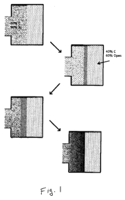
[0015] FIG. 1 is a flow diagram illustrating an example of cavity and preform
filling
according to an embodiment of the invention.
[0016] FIG. 2 is a depiction of a functional reinforcement gradient according
to an
embodiment of the invention.
[0017] FIG. 3 is an enlarged portion of the functional reinforcement gradient
of FIG. 2
according to an embodiment of the invention.
100181 FIGS. 4A-4C are enlarged views of the functional reinforcement gradient
of FIG. 2
according to an embodiment of the invention.
[0019] FIG. 5 is a perspective view of a brake assembly according to an
embodiment.
= [0020] Fig. 6 is a sectional view of a brake rotor according to an
embodiment.
[0021] Fig. 7 is a sectional view of a brake rotor according to an embodiment.
= [0022] FIGS. 8A-8E illustrate a method of making a metal matrix composite
brake rotor
according to an embodiment.
[0023] FIG 9. illustrates a method of making a metal matrix composite brake
drum according
to an embodiment.
CA 02907117 2015-09-15
WO 2014/149135
PCT/US2014/000050
6
[0024] FIG. 10 illustrates a view a close up views of a functional
reinforcement gradient
formed by a method of depositing a preform slurry according to an embodiment.
[0025] FIGS. 11A-11D illustrate a method for making a variable-density preform
according
to an embodiment.
[0026] FIG. 12 illustrates a method for making a variable-density preform
according to an
embodiment.
[0027] FIGS. 13 and 14 illustrate working surfaces for making a variable-
density preform
according to embodiments.
DETAILED DESCRIPTION
[0028] The following detailed description is exemplary in nature and is not
intended to limit
the scope, applicability, or configuration of the invention in any way.
Rather, the following
description provides some practical illustrations for implementing some
embodiments of the
present invention. Examples of constructions, materials, dimensions, and
manufacturing
processes are provided for selected elements, and all other elements employ
that which is
known to those of ordinary skill in the field of the invention. Those skilled
in the art will
recognize that many of the noted examples have a variety of suitable
alternatives.
[0029] Certain embodiments described in this disclosure provide and/or relate
to an
automotive brake rotor having a lightweight Metal Matrix Composition (MMC)
which
provides the ability to tailor the structure and the properties to meet
certain variable and sever
thermal and mechanical loadings. In addition to the thermal and mechanical
attributes, the
MMC technology provides a cost effective method for manufacturing brake
rotors.
[0030] According to some embodiments, one or more preforms can be manufactured
with
one or more Functional Reinforcement Gradients (FRG) as disclosed in
Applicant's co-
owned U.S. Patent No. 8,075,827 B2, titled "Variable-Density Preforms" issued
December
13, 2011, and in Applicant's co-owned and co-pending U.S. Patent Application
No.
13/323,118, titled "Variable-Density Preforms" filed December 13, 2011 (now
U.S. Patent
Application Publication No. 2012/0227624 Al, dated September 13, 2012). Each
of these
patents and publications is hereby incorporated herein in their entirety by
reference.
CA 02907117 2015-09-15
WO 2014/149135
PCT/US2014/000050
7
100311 Briefly, in accordance with an embodiment of the invention, one or more
FRG in a
preform is formed by establishing a flow of ceramic slurry into a mold and
then filtering the
slurry so as to extract and remove the liquid, thereby creating (or leaving
behind) a functional
gradient of the ceramic media contained in the slurry. In some embodiments,
such processes
can yield an FRG of approximately 30% to 45% by volume on the friction
surface.
100321 The instant application discloses embodiments wherein the volume
fraction can
range from this high reinforcement level found on the frictional surface to a
very low or
approximately 0% reinforcement level required in other areas. The disclosed
embodiments
are well suited for, but not limited to, automotive and airplane applications,
including rotor
brake systems for heavy trucks and/or trailers. Embodiments disclosed herein
provide one or
more advantages or features over past practices. For example, two-piece rotors
have been
used in industry (e.g., Brembo, Performance Friction) to date because it is
extremely difficult
to maintain rotor flatness during a transient braking event. The instant
application discloses
embodiments that overcome this and/or other deficiencies. In one example, the
use of a
functional reinforced gradient can assist in overcoming these types of
problems.
100331 As is generally known in the art, when a brake is used for slowing
and/or stopping a
moving object, the motion of the object gets transformed into heat and
transferred to the
brake disc in order to stop the moving vehicle. Upon application of the brake
actuator the
disk is clamped between the brake pads and rotational drag is created. This
clamping causes
energy transformation to take place and heat is generated. Under certain
operating
conditions, the heat energy does not get transferred to the disk uniformly
over the whole
surface due to the differences in tangential (or linear) velocities along the
radius of the brake
pad interface. The tangential speed of the brake rotor at any radial distance,
r, from the rotor
center is defined as the product of 27cr and the rotational speed (i.e.,
((2nr) x (RPM)). As will
be apparent, a higher velocity found at the outer positions corresponds to a
higher thermal
energy state (i.e. higher temperatures). Therefore, the rotor thermal load
carrying abilities at
the outer locations needs to handle the higher heat energy generated there.
100341 In accordance with an embodiment, higher heat capacity/handling can be
accomplished through placement of a higher concentration of ultra-high
temperature ceramic
material at specific locations on the rotor. In some embodiments, the
coefficient of thermal
expansion (CTE) is tailored with the changing of the ceramic component in the
MMC content
such that the rotor will expand and contract while remaining in-plane. Control
of expansion
CA 02907117 2015-09-15
WO 2014/149135
PCT/US2014/000050
8
and contraction is not possible if a monolithic material such as cast iron is
used in a brake
rotor. This is one of the reasons why 'brake jitter' is noticed in a
monolithic cast iron
automotive braking system.
[0035] Accordingly, some embodiments disclosed herein provide the ability to
control the
expansion and contraction of the rotor during braking (e.g., due to heating
and cooling),
enabling embodiments of the rotor(s) of the invention disclosed in the instant
disclosure to be
'hard mounted' to the hub. While other material options may contain better
material
properties in terms of maximum operation temperatures, the ability to tailor
(or customize)
the FRG material properties as taught herein allows for effective mounting of
the friction
surfaces directly to the hub section of the rotor and more effective thermal
management to
avoid brake fade (i.e., reduced breaking action).
Exemplary Embodiments
[0036] In accordance with some embodiments of the invention, the volume
fraction of
ceramic in the brake rotor changes across the braking surface extending
between the inside
and the outside diameters of the rotor. For instance, in a non-limiting
exemplary
embodiment, a location or section proximate the outermost extent (for example
proximate the
circumference) of the brake disc can include approximately 40% to 45% by
volume of
ceramic reinforcement and approximately 55% to 60% by volume of one or more
light alloy;
whereas at some location other than the outermost extent, e.g., proximate the
hub or at a
section or location between the hub and the circumference, the brake disc can
include
approximately 30% to 35% by volume of ceramic reinforcement and approximately
65% to
70% by volume of one or more light alloy. A method for making such changes in
volume
fraction is taught by Applicant's granted patent, U.S. Pat. No. 8,075,827 B2,
titled "Variable-
Density Preforms" issued December 13, 2011.
100371 In some cases distinct zones and interfaces between zones are provided.
For
example, certain embodiments of brake rotors include at least three functional
zones, viz., a)
friction interface (heating zone), b) venting (cooling zone) and c) mounting
hub (torque
transfer zone). In some cases these zones should or must have specific
material attributes for
the rotor, as a whole, to function properly. They also must have the proper
interfaces
between the zones. High ceramic on the rotor's breaking surface, for example
proximate the
outermost extent, must be graded to a lower ceramic content in the radial
direction extending
CA 02907117 2015-09-15
WO 2014/149135
PCT/US2014/000050
9
between the circumference and the hub, and through the thickness toward the
internal
venting.
[0038] In some cases an exemplary design according to some embodiments
involves the
use of two preforms to cast an article such as a blade or brake rotor. In some
cases the two
preforms are functionally graded in the radial direction. In some embodiments,
the blades are
infiltrated during the casting process that creates all of the rotor geometry
such as, but not
limited to, the hub, venting, and blade section, etc.
[0039] In certain embodiments, the effluent (or slurry) can be, but is not
limited to, an
aluminum or magnesium alloy containing ceramic particles and/or fibers.
[0040] In some embodiments, the at least one exit end or orifice can be, but
is not limited
to, a functionally graded porous preform.
[0041] In certain embodiments, a secondary gradient can be developed at the
metal-
preform interface of a casted article.
[0042] In some embodiments, the functional gradient in the interface regions
can serve, but
is not limited to, one or more of the following: (1) to provide a continually
changing ceramic
structure so as to minimize the stress riser at the interface from the
mechanical loading;
and/or (2) to grade the differences in the CTE at the interface to reduce the
thermal stresses
developed at the interface. In a braking event, the thermal load is just as
important if not
more important than that of the mechanical load.
[0043] In some embodiments of the invention, the thickness of the FRG can be
altered by
changing one or more of the density or the thickness or the composition of the
preform in the
die cavity. In certain embodiments, the preform and the incoming ceramic
carrying
aluminum can be tailored such that a predetermined FRG is achieved at the one
or more
interfaces. In some embodiments, the fraction of the fiber and/or particle
combination can be
altered to increase or decrease the thickness of the transition region.
100441 Accordingly, in some embodiments, the preform can contain ceramic
particles or
continuous ceramic fibers or discontinuous ceramic fibers or any combination
thereof in an
amount ranging between approximately 5% to approximately 70% by volume. In
certain
embodiments, the incoming alloy or slurry can include ceramic particles and/or
ceramic
CA 02907117 2015-09-15
, WO 2014/149135 PCT/US2014/000050
=
fibers in an amount ranging between approximately 5% to 40% by volume. In some
embodiments, vibration can be induced during the molding process to initiate
and/or enhance
the dispersion of the ceramic for providing a predetermined gradient.
[0045] As is well known in the art, different materials have different
coefficients of thermal
expansion (CTE) and therefore each expands at a different rate when heated.
Accordingly, if
different material having different CTE are attached to one another, the
thermal stress at the
interface and in the vicinity thereof can be substantially, and in some cases
significantly, high
when heated. Accordingly, providing or creating an FRG can reduce, minimize,
and/or
eliminate such thermal stresses as may arise due to the differences (or
mismatch) in the CTE
of the material used in the rotor.
[0046] Thermal stress in a constrained material is defined by a = aEATwhere a
is thermal
stress, a is the material's coefficient of thermal expansion (CTE), E is the
material's Young's
modulus and AT is the change in temperature. The CTE (a) of unreinforced
aluminum is
approximately 22.9 [tm/m- C (in the temperature range of approximately 20 C to
approximately 300 C); whereas for a 40% SiC particulate reinforced aluminum,
the CTE
(a)is approximately 11 pm/m- C. Accordingly, at approximately 300 C, the
stress in the
aluminum and at the interface between the aluminum and the MMC, respectively,
would be
aAl-MMC = ((22.9 ¨ 11 tim/m ¨ C) * 124E9 N/m2 * 300 C) = 443.39 MPa
(64.26ksi)o-Ai = ((22.9 ¨ 1111m/m ¨ C) * 69E9 N/m2 * 300 C) = 246.33 MPa
(36ksi)
[0047] This indicates that failure would occur in the MMC as the stress in
each material is
at the yield point of many alloys at room temperature and exceeds the yield of
almost all
reinforced and unreinforced aluminum alloys at 300 C. This is why a functional
gradient can
be desirable at this interface in some cases. If an incremental change in
volume fraction is
implemented, the thermal stress can be effectively managed.
100481 Taking the same temperature change as above but with an incremental CTE
difference (directly related to volume fraction of ceramic in the MMC by rule
of mixtures),
the stress at the interface is computed as:
am = ((22.9 ¨ 20 [intim ¨ C) * 69E9 N/m2 * 300 C) = 60 MPa (8.7ksi)
am-mmc = ((22.9 ¨ 20 [an/m ¨ C) * 124E9 N/m2 * 300 C) = 108 MPa (15.7ksi)
CA 02907117 2015-09-15
WO 2014/149135 PCT/US2014/000050
11
[0049] The resultant thermal stress is more manageable in both materials
and hence will be
able to handle the repeated loadings it will experience during braking events.
[0050] Accordingly, in an embodiment having the interface modification in
accordance
with an embodiment of the invention, the high volume fraction reinforcement
can be graded
to a low or no reinforcement smoothly.
[0051] Machining attributes ¨ SiC reinforced alloys are known to be very
difficult to drill
and tap. The ability of putting high levels of reinforcement only on the
braking surface helps
reduce machining time and cost. Historically, the rotors that have been in
production in
automotive applications have been fully reinforced all the way to the hub.
[0052] In some embodiments, the friction face may contain up to approximately
45%
ceramic while the hub of the rotor is > approximately 5% ceramic.
[0053] Non-limiting exemplary products in which the embodiments of the
invention
disclosed herein can be implemented include, but is not limited to, one or
more of those
illustrated and described below:
[0054] Some products this technology covers include the following: Automotive,
Military,
Commercial Truck and trailer rotors ¨ each friction face is reinforced with a
preform based
MMC and a functional gradient is added to between the preform areas and
unreinforced
areas.
[0055] An exemplary process in some embodiments means that the effluent passes
through
a porous media to build a functional gradient at the preform interface. In a
non-limiting
exemplary embodiment, the effluent in this case is a light alloy (aluminum,
magnesium or
silicon) that contains some percentage of ceramic media. For example Duralcan
(10% SiC
particulate). In accordance with an embodiment of the invention, the preform
can be used as
die wherein the effluent passes through but the particles are held back (or
retained) so as to
accumulate (or dam up).
[0056] With reference to the figure immediately below, a non-limiting
exemplary
embodiment includes approximately 90% aluminum and approximately 10% ceramic
short
=
fibers and/or particulate. Preform having an average of approximately 40%
ceramic
reinforcement and approximately 60% void.
CA 02907117 2015-09-15
WO 2014/149135 PCT/US2014/000050
12
(0057] In a non-limiting exemplary embodiment, the preform thickness for the
friction
surface of a rotor is set at approximately 0.234" thick (approximately 6mm)
for a square inch,
this is approximately 0.234 cubic inches of volume of which approximately
0.1404 cubic
inches (approximately 60%) is void (0.1404 cubic inches = 0.60 * 0.234 cubic
inches). The =
interface volume fraction will build to equal the preform volume fraction of
approximately
40% and decrease linearly away from the interface as the alloy is pressed from
the stir cast
material into the preform. The volume fraction evens out at the original MMC
stir cast
volume fraction (i.e. approximately 10%). So the slope to determine transition
zone
thickness at the interface is determined by the volume of alloy lost to the
preform and the
velocity of the shot.
100581 In accordance with an embodiment of the invention, a similar resultant
FRG MMC
structure can be obtained by a spray application of the preform. A non-
limiting exemplary
embodiment includes a process by which a high concentration of particles is
used in a
preform slurry and sprayed thru a nozzle (e.g., a venturi nozzle) onto a
heated surface or plate
on which vacuum is applied (to drive off the excess water/effluent). In some
embodiments of
the invention, the slurry composition can then be altered after the desired
build up of ceramic
structure to a higher fiber containing mix to create a less dense ceramic
structure. In certain
embodiments of the invention, such build up of an FRG can provide a structure
similar to that
previously described without the need to cast with a ceramic containing alloy.
In accordance
with an embodiment of the invention, the preform can be dried and fired, as
previously
described, to dry out moisture and/or burn out organic binders and/or sinter
the inorganic
binders to yield a preform ready for casting. In accordance with an embodiment
of the
invention, the structure can then be cast using a pressure infiltration method
(e.g., squeeze
casting). The figure below illustrates a non-limiting exemplary embodiment of
a structure
within a casting manufactured in accordance with an embodiment of the
invention.
100591 In some embodiments, the preform mix progresses from all fibers to a
combination
of low fibers and high particles to all particles. The light area, in an
embodiment of the
invention, is the alloy that has infiltrated the mix.
100601 In some embodiments, the preform mix progresses from all fibers to a
combination
of high fibers and low particles to a combination of low fibers and high
particles to all
particles.
CA 02907117 2015-09-15
WO 2014/149135 PCT/US2014/000050
13
[0061] In certain embodiments, the disclosed spraying process of the instant
invention
could be used to spray an existing preform (e.g., a preform having high volume
of SiC
particles) with a fiber-particle layer and then a fiber layer prior to squeeze
casting so as to
minimize stress concentrations that may arise due to differences in, and not
limited to, the
CTE and stiffness at one or more interfaces of mating materials.
[0062] In some cases a process by which a high concentration of particles is
used in a
preform slurry and sprayed or deposited thru a venturi nozzle or otherwise
deposited onto a
heated or unheated surface or plate on which vacuum and/or a centrifugal force
is applied (to
drive off the excess water/effluent). The slurry composition can then be
altered after the
desired build up of ceramic structure to a higher or lower fiber ceramic
containing density
mix to create a less/or more more or less dense ceramic structure. This build
up of an FRG
=
obtains a similar structure to that above without the need to cast with a
ceramic containing
alloy. This preform is dried and fired in the same common practice as before
spelled out in
authors' patent, but the drying process may also be used in between
compositional layer
changes as well.. To This drying process driesy the final moisture out, burns
out the organic
binders and to sinters the inorganic binders to obtain a preform ready for
casting.
[0063] = This structure can then be cast using a pressure infiltration method
(i.e. squeeze
casting). The final structure of the casting is seen below. The preform mix
moves from all
fiber to low fiber-high particle to all particle mix. The light area is the
alloy that has
infiltrated the mix.
[0064] Thus, embodiments of the invention are disclosed. Although the present
invention has
been described in considerable detail with reference to certain disclosed
embodiments, the
disclosed embodiments are presented for purposes of illustration and not
limitation and other
embodiments of the invention are possible. One skilled in the art will
appreciate that various
changes, adaptations, and modifications may be made without departing from the
spirit of the
invention and the scope of the appended claims.