Note: Descriptions are shown in the official language in which they were submitted.
CA 02907130 2015-12-30
EXTENSION POLE MECHANISM FOR PAINT ROLLER
I. Background
A. Field of the Invention
[0001] This invention is in the field of methods and apparatuses for extending
and contracting the length of poles used with paint related accessories and
more
specifically to methods and apparatuses for an extendable pole mechanism that
is easily
adjusted between a use condition and an adjustment condition with one hand.
B. Description of Related Art
[0002] It is well known in the paint industry to provide adjustable length
poles
that are designed to connect to and disconnect from paint accessories. A
painter, for
example, requires the pole holding a paint roller to be at a relatively
shorter length when
painting a surface at waist height but to be at a relatively longer length
when painting a
surface far above his/her head. Known adjustable length poles, however, have
disadvantages.
[0003] One disadvantage to known adjustable length poles is that they are
difficult and time consuming to use. Some, for example, require two hands to
adjust.
Another disadvantage is that they easily come "loose" from their setting,
causing the
poles to change their length when such change is not desirable. Yet another
disadvantage
is that many adjustable length poles are only adjustable in discrete length
increments. Still
another disadvantage is that known adjustable length poles quickly wear out,
increasing
costs.
[0004] What is needed, then, is an extendable pole mechanism that eliminates
or reduces the disadvantages just described. Painters would benefit from using
an
extendable pole mechanism that is durable, remains in its setting, provides
infinite length
adjustment, and can be easily operated with one hand.
1
CA 2907130 2017-04-07
Summary
[0005] According to one embodiment of this invention, an extendable pole
mechanism may be used with a first associated pole that is longitudinally
movable with
respect to a second associated pole to adjust the overall length of both
poles. The
extendable pole mechanism may comprise: a housing adapted to receive the first
and
second associated poles; a push member that: (1) is supported to the housing;
and, (2) is
moveable in a linear direction with respect to the housing; a trigger that:
(1) is supported
in the housing; (2) is moveable with respect to the housing; (3) contacts the
push member;
and (4) is pivotal with respect to the housing; and, a cam lever that: (1) is
supported in the
housing; (2) is moveable with respect to the housing; and, (3) contacts the
push member.
The extendable pole mechanism may be adjustable by pivoting the trigger with
respect to
the housing, to cause the push member to move with respect to the housing,
wherein the
cam lever is adapted to move with respect to the housing between: (1) a use
condition
where the first associated pole is held by contact with the cam lever in a
longitudinally
fixed position with respect to the second associated pole; and, (2) an
adjustment condition
where: (a) the first associated pole is not held by contact with the cam lever
in a
longitudinally fixed position with respect to the second associated pole; and,
(b) the first
associated pole is longitudinally moveable with respect to the second
associated pole.
100061 According to another embodiment of this invention, a method may
comprise the steps of: (A) providing an extendable pole mechanism for use with
a first
pole that is longitudinally movable with respect to a second pole; the
extendable pole
mechanism comprising: (1) a housing that receives the first and second poles;
(2) a push
member that: (a) is supported to the housing; and, (b) is moveable in a linear
direction
with respect to the housing; (3) a trigger that: (a) is supported to the
housing; (b) is
moveable with respect to the housing; (c) contacts the push member; and, (d)
is pivotal
with respect to the housing; and (4) a cam lever that: (a) is supported to the
housing; (b) is
moveable with respect to the housing; and, (c) contacts the push member; and,
(B) adjusting the extendable pole mechanism by pivoting the trigger with
respect to the
housing, to cause the push member to move with respect to the housing, to
cause the cam
lever to move with respect to the housing from: (1) a use condition where the
first pole is
held by contact with the cam lever in a longitudinally fixed position with
respect to the
second pole; into, (2) an adjustment condition where: (a) the first pole is
not held by
2
CA 2907130 2017-04-07
contact with the cam lever in a longitudinally fixed position with respect to
the second
pole; and, (b) the first pole is longitudinally moveable with respect to the
second pole to
adjust the overall length of both poles.
[0007] According to yet another embodiment of this invention, an extendable
pole mechanism may comprise: a first pole that is longitudinally movable with
respect to
a second pole to adjust the overall length of both poles; a housing that
receives the first
and second poles; a push member that: (1) is positioned within the housing;
and, (2) is
moveable in a linear direction with respect to the housing; a trigger that:
(1) is supported
to the housing; (2) is moveable with respect to the housing; (3) has a mid-
section that is
positioned outside the housing; (4) is pivotal with respect to the housing;
and, (5) contacts
the push member; a cam lever that: (1) is positioned within the housing; (2)
is moveable
with respect to the housing; (3) has a first surface that contacts the push
member; and,
(4) has a second surface; and, a cam holder that: (1) is positioned within the
housing; and,
(2) comprises a first contact surface that contacts the second surface of the
cam lever.
The extendable pole mechanism may be adjustable by pivoting the trigger with
respect to
the housing, to cause the push member to slide with respect to the housing, to
cause the
cam lever to pivot about its second surface on the first contact surface of
the cam holder
with respect to the housing between: (1) a use condition where the first pole
is held by
direct contact with the cam lever in a longitudinally fixed position with
respect to the
second pole; and, (2) an adjustment condition where: (a) the first pole is not
held by
contact with the cam lever in a longitudinally fixed position with respect to
the second
pole; and, (b) the first pole is longitudinally moveable with respect to the
second pole.
[0008] Numerous benefits and advantages of this invention will become
apparent to those skilled in the art to which it pertains upon reading and
understanding of
the following detailed specification.
III. Brief Description of the Drawings
[0009] The invention may take physical form in certain parts and arrangement
of parts, embodiments of which will be described in detail in this
specification and
illustrated in the accompanying drawings which form a part hereof and wherein:
3
CA 02907130 2015-12-30
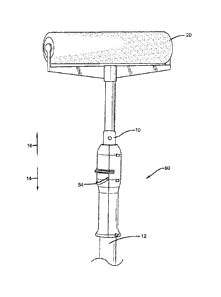
[0010] FIGURE 1 is a side assembly view of an extendable pole mechanism
according to some embodiments of this invention.
[0011] FIGURE 2 is a side view of a first housing portion.
[0012] FIGURE 3 is a bottom view of the first housing portion shown in
FIGURE 2.
[0013] FIGURE 2 is a side view of a second housing portion.
[0014] FIGURE 5 is a top view of the second housing portion shown in
FIGURE 4.
[0015] FIGURE 6 is a perspective view of a trigger.
[0016] FIGURE 7 is a first side perspective view of a cam lever.
[0017] FIGURE 8 is a second side perspective view of the cam lever shown in
FIGURE 7.
[0018] FIGURE 9 is a first side perspective view of a cam holder.
[0019] FIGURE 10 is a second side perspective view of the cam holder shown
in FIGURE 9.
[0020] FIGURE 11 is a top perspective view of a push member.
[0021] FIGURE 12 is a bottom perspective view of the push member shown in
FIGURE 11.
[0022] FIGURE 13 is a top view of the push member shown in FIGURE 11.
[0023] FIGURE 14 is a side view of the push member shown in FIGURE 11.
[0024] FIGURE 15 is a bottom perspective view of the extendable pole
mechanism in a use condition with the first pole and a portion of the housing
hidden.
[0025] FIGURE 16 is a side view of the extendable pole mechanism in an
adjustment condition with the first pole and a portion of the housing hidden.
4
CA 02907130 2015-12-30
[0026] FIGURE 17 is a side perspective view of the extendable pole
mechanism connected to a point roller according to some embodiments of this
invention
IV. Detailed Description
[0027] Referring now to the drawings wherein the showings are for purposes of
illustrating embodiments of the invention only and not for purposes of
limiting the same,
and wherein like reference numerals are understood to refer to like
components,
FIGURES 1 and 17 show a pair of poles 10, 12 that can be used with the
extendable pole
mechanism 50 of this invention. While the extendable pole mechanism 50 is
ideally
suited for use with paint accessories and the like, such as the paint roller
20 shown in
FIGURE 17, it is not limited to that application. Pole 10 may have an outside
diameter
that is received within an inside diameter of pole 12. As a result, pole 10 is
slideable
within pole 12 (and with respect to pole 12) in first direction 14 and second
direction 16.
When pole 10 is slid in direction 14, the overall length of both poles is
decreased. When
pole 10 is slid in direction 16, the overall length of both poles is
increased. Thus, a user
can adjust the overall length of the poles by sliding pole 10 with respect to
pole 12. Pole
may have a connection site 18 to which a paint accessory, such as paint roller
20, can
be attached. Pole 12 and/or the housing may serve as a handle for the user. In
one
specific embodiment, pole 10 is made of aluminum and pole 12 is made of
fiberglass to
provide good performance.
[0028] With reference now to FIGURE 1, the extendable pole mechanism 50
may be adjusted between a use condition, where pole 10 is held in a
longitudinally fixed
position with respect to pole 12, and an adjustment condition, where pole 10
can slide
longitudinally with respect to pole 12 so that the overall length can be
changed. The
extendable pole mechanism 50 may include a housing 52, a trigger 54, a cam
lever 56, a
cam holder 58, a push member 60, and a biasing device 62, which may be a
spring, as
shown. These components will now be described in more detail.
[0029] With reference now to FIGURES 1-5, the housing 52 may have first and
second portions 64, 66 that receive portions of poles 12 and 14, as shown, and
may be
attached to each other using connectors 68 received in openings 70. While six
threaded
5
CA 02907130 2015-12-30
connectors are used in the embodiment shown, the number and type can be any
chosen
with the sound judgment of a person of skill in the art. The first housing
portion 64 may
include shaft receiving grooves 72, an external protection ring 74, internal
lateral
extensions 76 and an internal longitudinal extension 78. A groove 80 may be
formed
between some of the lateral extensions 76, as shown. The external protection
ring 74
shown only extends a small amount around the external surface of the portion
64. The
second housing portion 66 may include shaft receiving grooves 82 and an
external
protection ring 84 that may extend all the way around the external surface of
the portion
66, as shown. The second housing portion 66 may have internal lateral
extensions 86 and
pole contact surfaces 88. Extensions 90 may define grooves 92 between them, as
shown.
The purposes for these components will be discussed below.
[00301 With reference now to FIGURES 1 and 6, the trigger 54 may have a
body 94 having a mid-section 96 and a pair or arms 98, 98 extending from the
mid-
section 96. For the embodiment shown, the body 94 is C-shaped. A pair of hands
100,
100 may extend from distal ends of the arms 98, 98, as shown. The hands 100,
100 may
extend inwardly and may have curved inner surfaces 104, as shown. A pair of
shaft
portions 102, 102 may extend from the distal ends of the arms 98, 98. For the
embodiment shown, the hands 100, 100 are attached to the shaft portions 102,
102 and
extend inwardly therefrom. The trigger 54 may be formed of any material chosen
with the
sound judgment of a person of skill in the art. In one embodiment, the trigger
54 is made
of plastic and in another it is made of a metal.
[0031] With reference now to FIGURES 1 and 7-8, the cam lever 56 may have
a body 106 having a mid-section 108 and a pair of arms 110, 110 extending from
the mid-
section 108. For the embodiment shown, the body 106 is C-shaped. First and
second
surfaces 112, 114 may extend longitudinally from the mid-section 108 as shown.
The
first surface 112 may extend above the second surface 114 and may be curved,
as shown,
to match the outside diameter of pole 10. Shoulder surfaces 116, 116, may be
formed at
proximal ends of the arms 110, 110 and the distal ends of the arms 110, 110
may curve
inwardly, as shown. The cam lever 56 may be formed of any material chosen with
the
sound judgment of a person of skill in the art.
6
CA 02907130 2015-12-30
[0032] With reference now to FIGURES 1 and 9-10, the cam holder 58 may
have a body 118 having a mid-section 120 and a pair or arms 122, 122 extending
from the
mid-section 120. For the embodiment shown, the body 118 is C-shaped. A pair of
surfaces 124, 124 may define with the mid-section 120 a groove 126 on the
external
surface of the mid-section 120, as shown. Hands 128, 128 may extend
longitudinally
from distal ends of the arms 122, 122, as shown. Contact surfaces 130, 130 may
be
defined on the hands 128, 128. The contact surfaces 130, 130 may be J-shaped,
as shown.
The cam holder 58 may be formed of any material chosen with the sound judgment
of a
person of skill in the art.
[0033] With reference now to FIGURES 1 and 11-14, the push member 60 may
have first and second ends 132, 134, a top 136 and a bottom 138. A chamber 140
may be
provided on the top 136, first end 132 and may receive the biasing device 62
shown in
FIGURE 1. The chamber 140 may be defined by a wall 142 at one end and may have
a
generally cylindrical shape, as shown. A slot 144 may be formed in a surface
defining the
bottom of the chamber 140 and may extend from the first end 132 toward the mid-
section
of the push member 60. Pole contact surfaces 146, 146 may extend from the
bottom 138
and may be curved, as shown, to match the outside diameter of pole 10. Grooves
148,
148 may be formed on sides of the push member 60 and a groove 150 may be
formed on
the bottom 138 of the push member 60, as shown. The second end 134 may have an
extension 152. The push member 60 may be formed of any material chosen with
the
sound judgment of a person of skill in the art.
[0034] The assembly of the extendable pole mechanism 50 will now be
described. The poles 10, 12 may be received in the housing portions 64, 66 as
shown in
FIGURES 1, 15 and 17. The push member 60 may be positioned primarily within
the
housing portion 64, between lateral extensions 76, as shown in FIGURE 15, and
the slot
144 may receive the extension 78. The pole contact surfaces 146 may receive
the outer
surface of the pole 10, though pole 10 is hidden in FIGURES 15 and 16. With
reference
to FIGURES 2-6 and 15-16, the shaft portions 102 of the trigger 54 may be
received in
the shaft receiving grooves 72 and 82 of the respective housing portions 64,
66. The
hands 100 of the trigger 54, see FIGURE 6, may be positioned within the
grooves 148
formed on the push member 60, as seen in FIGURE 16. The pole 10 may be
received
between the arms 98 of the trigger 54 and the mid-section 96 and arms 98 of
the trigger
7
CA 02907130 2015-12-30
54 may be positioned outside the housing 52. The cam holder 58 may be
positioned
within the housing 52 with the mid-section 120, see FIGURES 9-10, received in
the
groove 80, see FIGURE 3, formed in the first housing portion 64. This is shown
in
FIGURE 15. The pole 10 may be received between the arms 122 of the cam holder
58.
The hands 128 of the cam holder 58, see FIGURES 9-10, may be received in the
grooves 92, 92, see FIGURE 5, formed in the second housing portion 66. The cam
holder
58 thus may be held substantially fixed throughout the operation of the
extendable pole
mechanism 50. This is shown in FIGURES 15 and 16. The cam lever 56 may be
positioned within the housing 52 with the distal ends of the arms 110, 110,
see
FIGURES 7-8, received in the groove 150 formed on the push member 60, as shown
in
FIGURE 16. The pole 10 may be received between the arms 110 of the cam lever
56.
The shoulder surfaces 116, 116, see FIGURES 7-8, may be received on the
contact
surfaces 130 on the cam holder 58, see FIGURES 9-10 and 15.
[0035] With the extendable pole mechanism 50 assembled as described above,
its operation will now be described. FIGURE 15 shows the extendable pole
mechanism
50 in the use condition where pole 10 is held in a longitudinally fixed
position with
respect to pole 12. This is generally the preferred condition for using the
poles while
painting, for example. In this use condition, the pole 10 is received between
the arms 98
of the trigger 54, the arms 110 of the cam lever 56, and the arms 122 of the
cam holder
58. Note that the arms 98 of the trigger 54, the arms 110 of the cam lever 56,
and the
arms 122 of the cam holder 58 are substantially parallel with each other and
substantially
perpendicular to the longitudinal axes of the poles 10, 12. Note also that the
extension
152, see FIGURES 13-14 and 16, of the push member 60 may be received in the
groove
126, see FIGURES 9-10, in the cam holder 58. In this use condition, the bottom
of the
pole 10 rests securely on the first surface 112 of the cam lever 56, see
FIGURES 7-8.
[0036] To adjust the extendable pole mechanism 50 into the adjustment
condition, shown in FIGURES 16 and 17, all the user has to do is move the mid-
section
of the trigger 54 in direction 154 shown in FIGURE 15. This can easily be done
with a
single finger, perhaps the user's thumb. This motion causes the trigger 54 to
pivot about
its shaft portions 102, see FIGURE 6. As the trigger 54 is pivoted, the hands
100 within
the grooves 148 of the push member 60 push/slide the push member 60 in
direction 156,
shown in FIGURE 15. As the push member 60 is moved in direction 156, the
biasing
8
CA 02907130 2015-12-30
force of the spring 62 is overcome as the extension 78 is received farther
into the slot 144.
Movement of the push member 60 in direction 156 also causes the distal ends of
the arms
110, see FIGURES 7-8, which are received in groove 150 to move in direction
156. As
the arms 110 move in this way, the shoulder surfaces 116, see FIGURES 7-8,
pivot on the
contact surfaces 130, see FIGURES 9-10, of the cam holder 58 (and thus with
respect to
the cam holder). This movement of the trigger 54, and thus the push member 60
and cam
lever 56, may be continued until the adjustment condition shown in FIGURE 16
is
achieved.
[0037] With the extendable pole mechanism 50 in the adjustment condition
shown in FIGURES 16 and 17, the pole 10 remains between the arms 98 of the
trigger 54,
the arms 110 of the cam lever 56, and the arms 122 of the cam holder 58. The
arms of the
trigger 54 and the cam lever 56, however, are no longer parallel with the arms
of the cam
holder 58 and are no longer perpendicular to the longitudinal axes of the
poles 10, 12. In
this adjustment condition, the bottom of the pole 10 contacts first and second
surfaces
112, 114, see FIGURES 7-8, of the cam lever 56 and the pole contact surfaces
88, see
FIGURE 5, of the second housing portion 66. With the cam lever 56 angled in
this
manner, room for the pole 10 within the housing 52 is increased, making it
very easy to
adjust the relative longitudinal positions of the poles 10, 12 by sliding pole
10 with
respect to pole 12 to change the overall length. In fact, if the user simply
aims the pole 10
toward the ground while holding the housing 52 or the pole 12, gravity will
easily cause
the pole 10 to slide out of the housing 52 and pole 12 (in direction 16 in
FIGURE 1),
increasing the overall length. Similarly, if the user simply aims the pole 10
toward the
sky while holding the housing 52 or the pole 12, gravity will easily cause the
pole 10 to
slide into the housing 52 and pole 12 (in direction 14 in FIGURE 1),
decreasing the
overall length.
[0038] To adjust the extendable pole mechanism 50 from the adjustment
condition shown in FIGURES 16 and 17 to the use condition shown in FIGURE 15,
all
the user has to do is release the trigger 54. When the trigger 54 is released,
the biasing
force of the spring 62 will force/slide the push member 60 in direction 158,
shown in
FIGURES 15 and 16 until the components return to the relative positions shown
in
FIGURE 15.
9
CA 02907130 2015-12-30
[0039] Numerous embodiments have been described herein. The preferred
embodiments set out are not intended to limit the scope of the claims. The
claims should
be given the broadest interpretation consistent with the description as a
whole.
Having thus described the invention, it is now claimed: